1
To our customers,
Old Company Name in Catalogs and Other Documents
On April 1st, 2010, NEC Electronics Corporation merged with Renesas Technology
Corporation, and Renesas Electronics Corporation took over all the business of both
companies. Therefore, although the old company name remains in this document, it is a valid
Renesas Electronics document. We appreciate your understanding.
Renesas Electronics website: http://www.renesas.com
April 1st, 2010
Renesas Electronics Corporation
Issued by: Renesas Electronics Corporation (http://www.renesas.com)
Send any inquiries to http://www.renesas.com/inquiry.
Notice
1.
2.
3.
4.
5.
6.
7.
All information included in this document is current as of the date this document is issued. Such information, however, is
subject to change without any prior notice. Before purchasing or using any Renesas Electronics products listed herein, please
confirm the latest product information with a Renesas Electronics sales office. Also, please pay regular and careful attention to
additional and different information to be disclosed by Renesas Electronics such as that disclosed through our website.
Renesas Electronics does not assume any liability for infringement of patents, copyrights, or other intellectual property rights
of third parties by or arising from the use of Renesas Electronics products or technical information described in this document.
No license, express, implied or otherwise, is granted hereby under any patents, copyrights or other intellectual property rights
of Renesas Electronics or others.
You should not alter, modify, copy, or otherwise misappropriate any Renesas Electronics product, whether in whole or in part.
Descriptions of circuits, software and other related information in this document are provided only to illustrate the operation of
semiconductor products and application examples. You are fully responsible for the incorporation of these circuits, software,
and information in the design of your equipment. Renesas Electronics assumes no responsibility for any losses incurred by
you or third parties arising from the use of these circuits, software, or information.
When exporting the products or technology described in this document, you should comply with the applicable export control
laws and regulations and follow the procedures required by such laws and regulations. You should not use Renesas
Electronics products or the technology described in this document for any purpose relating to military applications or use by
the military, including but not limited to the development of weapons of mass destruction. Renesas Electronics products and
technology may not be used for or incorporated into any products or systems whose manufacture, use, or sale is prohibited
under any applicable domestic or foreign laws or regulations.
Renesas Electronics has used reasonable care in preparing the information included in this document, but Renesas Electronics
does not warrant that such information is error free. Renesas Electronics assumes no liability whatsoever for any damages
incurred by you resulting from errors in or omissions from the information included herein.
Renesas Electronics products are classified according to the following three quality grades: “Standard”, “High Quality”, and
“Specific”. The recommended applications for each Renesas Electronics product depends on the product’s quality grade, as
indicated below. You must check the quality grade of each Renesas Electronics product before using it in a particular
application. You may not use any Renesas Electronics product for any application categorized as “Specific” without the prior
written consent of Renesas Electronics. Further, you may not use any Renesas Electronics product for any application for
which it is not intended without the prior written consent of Renesas Electronics. Renesas Electronics shall not be in any way
liable for any damages or losses incurred by you or third parties arising from the use of any Renesas Electronics product for an
application categorized as “Specific” or for which the product is not intended where you have failed to obtain the prior written
consent of Renesas Electronics. The quality grade of each Renesas Electronics product is “Standard” unless otherwise
expressly specified in a Renesas Electronics data sheets or data books, etc.
“Standard”:
8.
9.
10.
11.
12.
Computers; office equipment; communications equipment; test and measurement equipment; audio and visual
equipment; home electronic appliances; machine tools; personal electronic equipment; and industrial robots.
“High Quality”: Transportation equipment (automobiles, trains, ships, etc.); traffic control systems; anti-disaster systems; anticrime systems; safety equipment; and medical equipment not specifically designed for life support.
“Specific”:
Aircraft; aerospace equipment; submersible repeaters; nuclear reactor control systems; medical equipment or
systems for life support (e.g. artificial life support devices or systems), surgical implantations, or healthcare
intervention (e.g. excision, etc.), and any other applications or purposes that pose a direct threat to human life.
You should use the Renesas Electronics products described in this document within the range specified by Renesas Electronics,
especially with respect to the maximum rating, operating supply voltage range, movement power voltage range, heat radiation
characteristics, installation and other product characteristics. Renesas Electronics shall have no liability for malfunctions or
damages arising out of the use of Renesas Electronics products beyond such specified ranges.
Although Renesas Electronics endeavors to improve the quality and reliability of its products, semiconductor products have
specific characteristics such as the occurrence of failure at a certain rate and malfunctions under certain use conditions. Further,
Renesas Electronics products are not subject to radiation resistance design. Please be sure to implement safety measures to
guard them against the possibility of physical injury, and injury or damage caused by fire in the event of the failure of a
Renesas Electronics product, such as safety design for hardware and software including but not limited to redundancy, fire
control and malfunction prevention, appropriate treatment for aging degradation or any other appropriate measures. Because
the evaluation of microcomputer software alone is very difficult, please evaluate the safety of the final products or system
manufactured by you.
Please contact a Renesas Electronics sales office for details as to environmental matters such as the environmental
compatibility of each Renesas Electronics product. Please use Renesas Electronics products in compliance with all applicable
laws and regulations that regulate the inclusion or use of controlled substances, including without limitation, the EU RoHS
Directive. Renesas Electronics assumes no liability for damages or losses occurring as a result of your noncompliance with
applicable laws and regulations.
This document may not be reproduced or duplicated, in any form, in whole or in part, without prior written consent of Renesas
Electronics.
Please contact a Renesas Electronics sales office if you have any questions regarding the information contained in this
document or Renesas Electronics products, or if you have any other inquiries.
(Note 1) “Renesas Electronics” as used in this document means Renesas Electronics Corporation and also includes its majorityowned subsidiaries.
(Note 2) “Renesas Electronics product(s)” means any product developed or manufactured by or for Renesas Electronics.
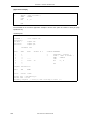
User’s Manual
RA78K0R Ver. 1.20
Assembler Package
Language
Target Devices
78K0R Microcontrollers
Document No. U18546EJ1V0UM00 (1st edition)
Date Published October 2007
© NEC Electronics Corporation 2007
Printed in Japan
[MEMO]
2
User’s Manual U18546EJ1V0UM
Windows is either registered trademarks or trademarks of Microsoft Corporation in the United States
and/or other countries.
• The information in this document is current as of October, 2007. The information is subject to
change without notice. For actual design-in, refer to the latest publications of NEC Electronics data
sheets or data books, etc., for the most up-to-date specifications of NEC Electronics products. Not
all products and/or types are available in every country. Please check with an NEC Electronics sales
representative for availability and additional information.
• No part of this document may be copied or reproduced in any form or by any means without the prior
written consent of NEC Electronics. NEC Electronics assumes no responsibility for any errors that may
appear in this document.
• NEC Electronics does not assume any liability for infringement of patents, copyrights or other intellectual
property rights of third parties by or arising from the use of NEC Electronics products listed in this document
or any other liability arising from the use of such products. No license, express, implied or otherwise, is
granted under any patents, copyrights or other intellectual property rights of NEC Electronics or others.
• Descriptions of circuits, software and other related information in this document are provided for illustrative
purposes in semiconductor product operation and application examples. The incorporation of these
circuits, software and information in the design of a customer's equipment shall be done under the full
responsibility of the customer. NEC Electronics assumes no responsibility for any losses incurred by
customers or third parties arising from the use of these circuits, software and information.
• While NEC Electronics endeavors to enhance the quality, reliability and safety of NEC Electronics products,
customers agree and acknowledge that the possibility of defects thereof cannot be eliminated entirely. To
minimize risks of damage to property or injury (including death) to persons arising from defects in NEC
Electronics products, customers must incorporate sufficient safety measures in their design, such as
redundancy, fire-containment and anti-failure features.
• NEC Electronics products are classified into the following three quality grades: "Standard", "Special" and
"Specific".
The "Specific" quality grade applies only to NEC Electronics products developed based on a customerdesignated "quality assurance program" for a specific application. The recommended applications of an NEC
Electronics product depend on its quality grade, as indicated below. Customers must check the quality grade of
each NEC Electronics product before using it in a particular application.
"Standard": Computers, office equipment, communications equipment, test and measurement equipment, audio
and visual equipment, home electronic appliances, machine tools, personal electronic equipment
and industrial robots.
"Special": Transportation equipment (automobiles, trains, ships, etc.), traffic control systems, anti-disaster
systems, anti-crime systems, safety equipment and medical equipment (not specifically designed
for life support).
"Specific": Aircraft, aerospace equipment, submersible repeaters, nuclear reactor control systems, life
support systems and medical equipment for life support, etc.
The quality grade of NEC Electronics products is "Standard" unless otherwise expressly specified in NEC
Electronics data sheets or data books, etc. If customers wish to use NEC Electronics products in applications
not intended by NEC Electronics, they must contact an NEC Electronics sales representative in advance to
determine NEC Electronics' willingness to support a given application.
(Note)
(1) "NEC Electronics" as used in this statement means NEC Electronics Corporation and also includes its
majority-owned subsidiaries.
(2) "NEC Electronics products" means any product developed or manufactured by or for NEC Electronics (as
defined above).
M8E 02. 11-1
User’s Manual U18546EJ1V0UM
3
[MEMO]
4
User’s Manual U18546EJ1V0UM
INTRODUCTION
This manual is designed to facilitate correct understanding of the basic functions of each program in the
RA78K0R Assembler Package (hereafter called RA78K0R) and the methods of describing source programs.
This manual does not cover how to operate the respective programs of the RA78K0R. Therefore, after you
have comprehended the contents of this manual, read the RA78K0R Ver. 1.20 Assembler Package Operation
User’s Manual (U18547E) (hereafter called Operation) to operate each program in the assembler package.
Descriptions related to the RA78K0R in this manual apply to Ver. 1.20 or later.
[Target Readers]
This manual is intended for user engineers who understand the functions and instructions of the microcontroller
(78K0R Microcontroller) subject to development.
[Organization]
This manual consists of the following six chapters and appendices:
CHAPTER 1
GENERAL
Outlines all of the basic functions of the RA78K0R.
CHAPTER 2
HOW TO DESCRIBE SOURCE PROGRAMS
Outlines how to describe source programs, and explains the operators of the assembler.
CHAPTER 3
DIRECTIVES
Explains how to write and use directives, including application examples.
CHAPTER 4
CONTROL INSTRUCTIONS
Explains how to write and use control instructions, including application examples.
CHAPTER 5
MACROS
Explains all macro functions, including macro definition, macro reference, and macro
expansion.
Macro directives are explained in CHAPTER 3 DIRECTIVES.
CHAPTER 6
PRODUCT UTILIZATION
Introduces some measures recommended for describing a source program.
APPENDIXES
These contain a list of reserved words, a list of directives, and an index.
The instruction sets are not detailed in this manual. For these instructions, refer to the user’s manual of the
microcontroller for which software is being developed.
Also, for instructions on architecture, refer to the user's manual (hardware version) of each microcontroller for
which software is being developed.
User’s Manual U18546EJ1V0UM
5
[Macros]
Those using an assembler for the first time are encouraged to read from CHAPTER 1 GENERAL of this
manual. Those who have a general knowledge of assembler programs may skip CHAPTER 1 GENERAL of this
manual. However, be sure to read 1.2 Reminders Before Program Development and CHAPTER 2 HOW TO
DESCRIBE SOURCE PROGRAMS.
Those who wish to know the directives and control instructions of the assembler are encouraged to read
CHAPTERS 3 DIRECTIVES and 4 CONTROL INSTRUCTIONS, respectively. The format, function, use, and
application examples of each directive or control instruction are detailed in these chapters.
[Conventions]
…
The following symbols and abbreviations are used throughout this manual:
:
[ ]:
Same format is repeated.
Characters enclosed in these brackets can be omitted.
{ }:
One of the items in { } is selected.
“ ”:
Characters enclosed in “ ”(quotation marks) are a character string.
‘ ’:
Characters enclosed in ‘ ’ (single quotation marks) are a character string.
( ):
Characters between parentheses are a character string.
< >:
Characters (mainly title) enclosed in these brackets are a character string.
__:
An underline is used to indicate an important point or input character strings.
Δ:
Indicates one or more blanks characters or tabs.
/:
Character delimiter
∼:
Continuity
Boldface: Characters in boldface are used to indicate an important point or reference point.
6
User’s Manual U18546EJ1V0UM
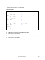
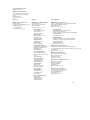
[Related Documents]
The documents (user’s manuals) related to this manual are listed below.
The related documents indicated in this publication may include preliminary versions.
However, preliminary versions are not marked as such.
Document Name
RA78K0R Ver. 1.20 Assembler Package
CC78K0R Ver. 2.00 C Compiler
SM+ System Simulator
Document No.
Operation
U18547E
Language
This manual
Operation
U18549E
Language
U18548E
Operation
PM+ Ver. 6.30 Project Manager
ID78K0R-QB Ver .3.20 Integrated Debugger
Caution
U18010E
U18416E
Operation
U17839E
The related documents listed above are subject to change without notice. Be sure to use the
latest version of each document for designing.
User’s Manual U18546EJ1V0UM
7
[MEMO]
8
User’s Manual U18546EJ1V0UM
CONTENTS
CHAPTER 1 GENERAL ... 14
1.1 Assembler Overview ... 14
1.1.1 What is an assembler? ... 15
1.1.2 Development of microcontroller-applied products and the role of RA78K0R ... 16
1.1.3 Relocatable assembler ... 17
1.2 Reminders Before Program Development ... 19
1.2.1 Quantitative limits for RA78K0R ... 19
1.3 Features of RA78K0R ... 21
CHAPTER 2 HOW TO DESCRIBE SOURCE PROGRAMS ... 22
2.1 Basic Configuration ... 22
2.1.1 Module header ... 23
2.1.2 Module body ... 24
2.1.3 Module tail ... 24
2.1.4 Overall configuration of source program ... 25
2.1.5 Description example ... 26
2.2 Description Method ... 29
2.2.1 Configuration ... 29
2.2.2 Character set ... 30
2.2.3 Symbol field ... 32
2.2.4 Mnemonic field ... 36
2.2.5 Operand field ... 36
2.2.6 Comment field ... 40
2.3 Expressions and Operators ... 41
2.4 Arithmetic Operators ... 44
+ ... 45
- ... 46
* ... 47
/ ... 48
MOD ... 49
+ sign ... 50
- sign ... 51
2.5 Logical Operators ... 52
NOT ... 53
AND ... 54
OR ... 55
XOR ... 56
2.6 Relational Operators ... 57
EQ (=) ... 58
NE (< >) ... 59
GT (>) ... 60
GE (>=) ... 61
LT (<) ... 62
LE (<=) ... 63
2.7 Shift Operators ... 64
SHR ... 65
SHL ... 66
2.8 Byte-Separating Operators ... 67
HIGH ... 68
LOW ... 69
2.9 Word-Separating Operators ... 70
HIGHW ... 71
LOWW ... 72
2.10 Special Operators ... 73
DATAPOS ... 74
User’s Manual U18546EJ1V0UM
9
BITPOS ... 75
MASK ... 76
2.11 Other Operator ... 77
( ) ... 78
2.12 Restrictions on Operations ... 79
2.12.1 Operators and relocation attributes ... 79
2.12.2 Operators and symbol attributes ... 82
2.12.3 How to check restrictions on the operation ... 84
2.13 Definition of Absolute Expression ... 85
2.14 Bit Position Specifier ... 86
. ... 87
2.15 Characteristics of Operands ... 89
2.15.1 Size and address range of operand value ... 89
2.15.2 Size of operands required for instructions ... 95
2.15.3 Symbol attributes and relocation attributes of operands ... 95
CHAPTER 3 DIRECTIVES ... 99
3.1 Overview ... 99
3.2 Segment Definition Directives ... 100
CSEG ... 102
DSEG ... 106
BSEG ... 111
ORG ... 115
3.3 Symbol Definition Directives ... 118
EQU ... 119
SET ... 123
3.4 Memory Initialization and Area Reservation Directives ... 125
DB ... 126
DW ... 128
DG ... 130
DS ... 132
DBIT ... 134
3.5 Linkage Directives ... 135
EXTRN ... 136
EXTBIT ... 138
PUBLIC ... 140
3.6 Object Module Name Declaration Directive ... 142
NAME ... 143
3.7 Automatic Branch Instruction Selection Directives ... 144
BR ... 145
CALL ... 147
3.8 Macro Directives ... 149
MACRO ... 150
LOCAL ... 152
REPT ... 155
IRP ... 157
EXITM ... 159
ENDM ... 162
3.9 Assembly Termination Directive ... 164
END ... 165
CHAPTER 4 CONTROL INSTRUCTIONS ... 166
4.1 Overview ... 166
4.2 Processor Type Specification Control Instruction ... 168
PROCESSOR ... 169
4.3 Debug Information Output Control Instructions ... 170
DEBUG/NODEBUG ... 171
DEBUGA/NODEBUGA ... 172
4.4 Cross-Reference List Output Specification Control Instructions ... 173
XREF/NOXREF ... 174
SYMLIST/NOSYMLIST ... 175
4.5 Inclusion Control Instruction ... 176
lNCLUDE ... 177
10
User’s Manual U18546EJ1V0UM
4.6 Assembly List Control Instructions ... 179
EJECT ... 180
LIST/NOLIST ... 182
GEN/NOGEN ... 184
COND/NOCOND ... 186
TITLE ... 187
SUBTITLE ... 189
FORMFEED/NOFORMFEED ... 192
WIDTH ... 193
LENGTH ... 194
TAB ... 195
4.7 Conditional Assembly Control Instructions ... 196
IF/_IF/ELSEIF/_ELSEIF/ELSE/ENDIF ... 197
SET/RESET ... 201
4.8 Kanji Code (2-byte code) Control Instruction ... 203
KANJICODE ... 204
4.9 Other Control Instructions ... 205
CHAPTER 5 MACROS ... 206
5.1 Overview ... 206
5.2 Utilization of Macros ... 207
5.2.1 Macro definition ... 207
5.2.2 Macro reference ... 208
5.2.3 Macro expansion ... 209
5.2.4 Application example ... 209
5.3 Symbols within Macros ... 210
5.4 Macro Operators ... 212
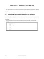
CHAPTER 6 PRODUCT UTILIZATION ... 214
6.1 Saving Time and Trouble in Starting Up the Assembler ... 214
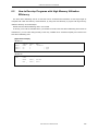
6.2 How to Develop Programs with High Memory Utilization Efficiency ... 215
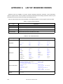
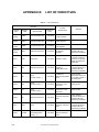
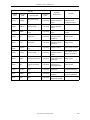
APPENDIX A LIST OF RESERVED WORDS ... 216
APPENDIX B LIST OF DIRECTIVES ... 218
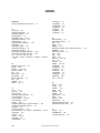
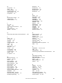
INDEX ... 220
User’s Manual U18546EJ1V0UM
11
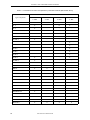
LIST OF FIGURES
Figure No. Title , Page
1-1
1-2
1-3
2-1
2-2
2-3
2-4
2-5
3-1
3-2
12
RA78K0R Assembler Package ... 14
Flow of Assembler ... 15
Development Process of Microcontroller-Applied Products ... 16
Configuration of Source Module ... 22
Overall Configuration of Source Module ... 25
Examples of Source Module Configurations ... 25
Configuration of Sample Program ... 26
Fields That Make Up a Statement ... 29
Memory Location of Segments ... 101
Relationship of Symbols Between Two Modules ... 135
User’s Manual U18546EJ1V0UM
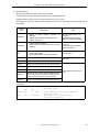
LIST OF TABLES
Table No. Title , Page
2-1
2-2
2-3
2-4
2-5
2-6
2-7
2-8
2-9
2-10
2-11
2-12
2-13
2-14
3-1
3-2
3-3
3-4
3-5
4-1
4-2
A-1
A-2
B-1
Instructions That Can Be Described in Module Header ... 23
Alphanumeric Characters ... 30
Special Characters ... 30
Types of Operators ... 41
Order of Precedence of Operators ... 42
Types of Relocation Attributes ... 79
Combinations of Terms and Operators by Relocation Attribute (Relocatable Terms) ... 80
Combinations of Terms and Operators by Relocation Attribute (External Reference Terms) ... 81
Types of Symbol Attributes in Operations ... 82
Combinations of Terms and Operators by Symbol Attribute ... 83
Ranges of Operand Values of Instructions ... 89
Ranges of Operand Values of Directives ... 94
Properties of Described Symbols as Operands ... 96
Properties of Described Symbols as Operands of Directives ... 97
List of Directives ... 99
Segment Definition Methods and Memory Address Location ... 100
Relocation Attributes of CSEG ... 103
Relocation Attributes of DSEG ... 107
Relocation Attributes of BSEG ... 112
List of Control Instructions ... 166
Control Instructions and Assembler Options ... 167
Types of Reserved Words ... 216
List of Reserved Words ... 216
List of Directives ... 218
User’s Manual U18546EJ1V0UM
13
CHAPTER 1 GENERAL
CHAPTER 1
GENERAL
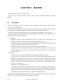
This chapter describes the role of the RA78K0R in microcontroller software development and the features of the
RA78K0R.
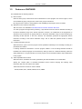
1.1
Assembler Overview
The RA78K0R Assembler Package (hereafter referred to as RA78K0R) is a generic term for a series of
programs designed to translate source programs coded in the assembly language for 78K0R Series
microcontrollers into machine language coding.
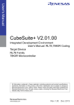
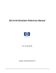
The RA78K0R contains 5 programs: Assembler, Linker, Object Converter, Librarian, and List Converter.
In addition, a PM+ that helps you perform a series of operations including editing, compiling/assembling, linking,
and debugging your program on Windows® is also supplied with the RA78K0R.
Figure 1-1 RA78K0R Assembler Package
Assembler
Linker
Object Converter
RA78K0R Assembler Package
Librarian
List Converter
PM+
14
User’s Manual U18546EJ1V0UM
CHAPTER 1 GENERAL
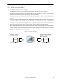
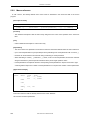
1.1.1
What is an assembler?
(1) Assembly language and machine language
An assembly language is the most fundamental programming language for a microcontroller.
Programs and data are required for the microprocessor in a microcontroller to do its job. These programs
and data must be written by users to the memory of the microcontroller.
The programs and data handled by the microcontroller are collections of binary numbers called machine
language.
For users, however, machine language code is difficult to remember, causing errors to occur frequently.
Fortunately, methods exist whereby English abbreviations or mnemonics are used to represent the
meanings of the original machine language codes in a way that is easy for user to comprehend. The basic
programming language system that uses this symbolic coding is called an assembly language.
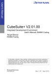
Since machine language is the only programming language in which a microcontroller can handle programs,
however, another program is required that translates programs created in assembly language into machine
language. This program is called an assembler.
Figure 1-2 Flow of Assembler
Program written in
assembly language
(Source module file)
Program written in machine
language (collections of
binary numbers)
(Assembler)
User’s Manual U18546EJ1V0UM
(Object module file)
15
CHAPTER 1 GENERAL
1.1.2
Development of microcontroller-applied products and the role of
RA78K0R
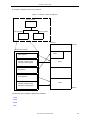
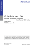
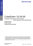
The following figure illustrates the position of "assemble in the product development process".
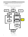
Figure 1-3 Development Process of Microcontroller-Applied Products
Product planning
System design
Hardware
development
Software
development
Logic design
Software design
Manufacturing
Program coding in
assembly language
Position of
RA78K0R
Assemble
Inspection
NO
NO
OK?
OK?
YES
YES
Debugging
NO
OK?
YES
System evaluation
Product marketing
16
User’s Manual U18546EJ1V0UM
CHAPTER 1 GENERAL
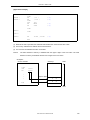
1.1.3
Relocatable assembler
The machine language translated from a source language by the assembler is written to the memory of the
microcontroller before use. To do this, the location in memory where each machine language instruction is to be
written must already be determined.
Therefore, information is added to the machine language assembled by the assembler, stating where in memory
each machine language instruction is to be located.
Depending on the method of locating addresses to machine language instructions, assemblers can be broadly
divided into "absolute assemblers" and "relocatable assemblers".
- Absolute assembler
An absolute assembler locates machine language instructions assembled from the assembly language to
absolute addresses.
- Relocatable assembler
In a relocatable assembler, the addresses determined for the machine language instructions assembled from
the assembly language are tentative.
Absolute addresses are determined subsequently by the linker.
In the past, when a program was created with an absolute assembler, programmers had to, as a rule, complete
programming at the same time. However, if all the components of a large program are created as a single entity,
the program becomes complicated, making analysis and maintenance of the program difficult. To avoid this, such
large programs are developed by dividing them into several subprograms, called modules, for each functional unit.
This programming technique is called modular programming.
A relocatable assembler is an assembler suitable for modular programming, which has the following advantages:
(1) Increase in development efficiency
It is difficult to write a large program all at the same time. In such cases, dividing the program into modules
for individual functions enables two or more programmers to develop subprograms in parallel to increase
development efficiency.
Furthermore, if any bugs are found in the program, it is not necessary to assemble the entire program just to
correct one part of the program; just the module that must be corrected can be reassembled. This shortens
the debugging time.
User’s Manual U18546EJ1V0UM
17
CHAPTER 1 GENERAL
Program consisting of a single
module
Program consisting of two or
more modules
Module
Bugs are
found!
Bugs are
found!
xxx
Module
Entire program
must be
assembled
again.
Module
Only this module
needs to be
assembled
again.
xxx
Module
Module
(2) Utilization of resources
Highly reliable, highly versatile modules that have been previously created can be reused for the creation of
another program. If you accumulate such high-versatility modules as software resources, you can save time
and labor in developing a new program.
Module A
Module B
Module C
New module
Module A
New module
Module D
New program
18
User’s Manual U18546EJ1V0UM
Module D
CHAPTER 1 GENERAL
1.2
Reminders Before Program Development
Refer to the following before beginning program development.
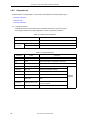
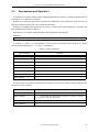
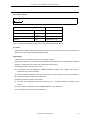
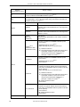
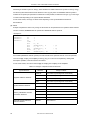
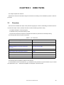
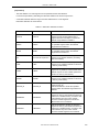
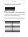
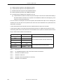
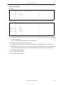
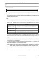
1.2.1
Quantitative limits for RA78K0R
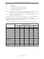
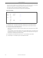
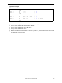
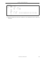
(1) Quantitative limits for assembler
Item
Maximum Performance
Characteristics
Number of symbols (local + public)
65,535 symbols
Number of symbols for which cross-reference list can be output
65,534 symbolsNote 1
Maximum size of macro body for one macro reference
1 M bytes
Total size of all macro bodies
10 M bytes
Number of segments in one file
256 segments
Macro and include specifications in one file
10,000
Macro and include specifications in one include file
10,000
Relocation dataNote 2
65,535 items
Line number data
65,535 items
Number of BR/CALL directives in one file
32,767 directives
Number of characters per line
2,048 charactersNote 3
Symbol length
Number of definitions of switch
256 characters
nameNote 4
1,000
Character length of switch nameNote 4
31 characters
Character length of segment name
8 characters
Character length of module name (NAME quasi directive)
256 characters
Number of virtual parameters in MACRO quasi directive
16 parameters
Number of actual parameters in macro reference
16 parameters
Number of actual parameters in IRP quasi directive
16 parameters
Number of local symbols in macro body
64 symbols
Total number of local symbols in expanded macro
65,535 symbols
Nesting levels in macro (macro reference, REPT quasi directive, IRP
quasi directive)
8 levels
Number of characters specifiable by TITLE control instruction, the -lh
option
60 charactersNote 5
Number of characters specifiable by SUBTITLE control instruction
72 characters
Include file nesting levels in 1 file
8 levels
Conditional assembly nesting levels
8 levels
Number of include file paths specifiable by the -i option
64 paths
User’s Manual U18546EJ1V0UM
19
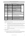
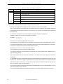
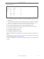
CHAPTER 1 GENERAL
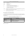
Item
Number of symbols definable by the -d option
Note 1
Maximum Performance
Characteristics
30 symbols
Excluding the number of module names and section names.
Memory is used. If there is no memory, a file is used.
Note 2
Information to be passed to the linker if the symbol value cannot be resolved by the assembler.
For example, if an externally referenced symbol is to be referenced by the MOV instruction, two
pieces of relocation information are generated in a .rel file.
Note 3
Including CR and LF codes. If more than 2048 characters are written on one line, a warning
message is output and the 2049th character and those that follow are ignored.
Note 4
The switch name is set as true/false by the SET/RESET quasi directive and is used by $IF, etc.
Note 5
If the maximum number of characters that can be specified in one line of the assemble list file
("X") is 119, this figure will be "X - 60" or less.
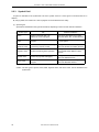
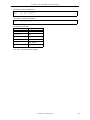
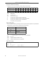
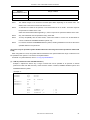
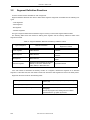
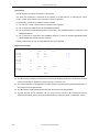
(2) Quantitative limits for linker
Item
Number of symbols (local + public)
65,535 symbols
Line number data of same segment
65,535 items
Number of segments
65,535 segmentsNote
Number of input modules
1,024 modules
Character length of memory area name
256 characters
Number of memory areas
100 areasNote
Number of library files specifiable by the -b option
64 files
Number of include file paths specifiable by the -i option
64 paths
Note Including those defined by default.
20
Maximum Performance
Characteristics
User’s Manual U18546EJ1V0UM
CHAPTER 1 GENERAL
1.3
Features of RA78K0R
The RA78K0R has the following features:
(1) Macro function
When the same group of instructions must be described in a source program over and over again, a macro
can be defined by giving a single macro name to the group of instructions.
By using this macro function, coding efficiency and readability of the program can be increased.
(2) Optimize function of branch instructions
"BR" and "CALL" are available as Automatic Branch Instruction Selection Directives.
To create a program with high memory efficiency, a byte branch instruction must be described according to
the branch destination range of the branch instruction. However, it is troublesome for the programmer to
describe a branch instruction by paying attention to the branch destination range for each branching. By
describing the BR directive or the CALL directive, the assembler generates the appropriate branch
instruction according to the branch destination range. This is called the optimize function of branch
instructions.
(3) Conditional assembly function
With this function, a part of a source program can be specified for assembly or non-assembly according to a
predetermined condition.
If a debug statement is described in a source program, whether or not the debug statement should be
translated into machine language can be selected by setting a switch for conditional assembly. When the
debug statement is no longer required, the source program can be assembled without major modifications
to the program.
(4) 78K0 compatible macro function
With this function, assembler source files generated by the 78K0 assembler can be assembled.
Specify the -compati option to assemble assembler sources without changing the following 78K0
instructions that cannot be used for the 78K0R.
78K0 instructions that cannot be used for 78K0R:
DIVUW, ROR4, ROL4, ADJBA, ADJBS, CALLF, DBNZ
User’s Manual U18546EJ1V0UM
21
CHAPTER 2 HOW TO DESCRIBE SOURCE PROGRAMS
CHAPTER 2
HOW TO DESCRIBE SOURCE
PROGRAMS
This chapter describes the description methods, expressions and operators of the source program.
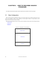
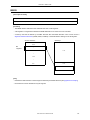
2.1
Basic Configuration
When a source program is described by dividing it into several modules, each module that becomes the unit of
input to the assembler is called a source module (if a source program consists of a single module, "source
program" means the same as "source module").
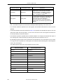
Each source module that becomes the unit of input to the assembler consists mainly of the following three parts:
- Module header
- Module body
- Module tail
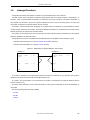
Figure 2-1 Configuration of Source Module
Module header
Module body
Module tail
22
User’s Manual U18546EJ1V0UM
CHAPTER 2 HOW TO DESCRIBE SOURCE PROGRAMS
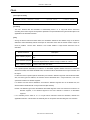
2.1.1
Module header
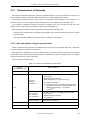
In the module header, the control instructions shown below can be described. Note that these control instructions
can only be described in the module header.
Also, the module header can be omitted.
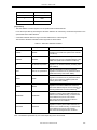
Table 2-1 Instructions That Can Be Described in Module Header
Item That Can Be Described
Explanation
- PROCESSOR
- XREF/NOXREF
- DEBUG/NODEBUG,
DEBUGA/NODEBUGA
- TITLE
- SYMLIST/NOSYMLIST
- FORMFEED/NOFORMFEED
- WIDTH
- LENGTH
- TAB
- KANJICODE
Control instructions that have the same
functions as assembler options
Special control instructions output by
high-level programs such as C compiler
Chapter/Section
in This Manual
CHAPTER 4 CONTROL
INSTRUCTIONS
- TOL_INF
- DGS
- DGL
User’s Manual U18546EJ1V0UM
23
CHAPTER 2 HOW TO DESCRIBE SOURCE PROGRAMS
2.1.2
Module body
In the module body, the following instructions cannot be described:
- Control instructions that have the same functions as assembler options
All other directives, control instructions, and instructions can be described in the module body.
The module body must be described by dividing it into units, called "segments".
The user may define the following four segments with a directive corresponding to each segment:
- Code segment
Must be defined with the CSEG directive.
- Data segment
Must be defined with the DSEG directive.
- Bit segment
Must be defined with the BSEG directive.
- Absolute segment
Must be defined by specifying a location address for the relocation attribute (AT location address) with the
CSEG, DSEG, or BSEG directive. This segment may also be defined with the ORG directive.
The module body may be configured with any combination of segments.
However, a data segment and a bit segment should be defined before a code segment.
2.1.3
Module tail
The module tail indicates the end of the source module. The END directive must be described in this part.
If anything other than a comment, a blank, a tab, or a line feed code is described following the END directive, the
assembler will output a warning message and ignore the characters described after the END directive.
24
User’s Manual U18546EJ1V0UM
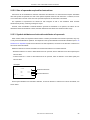
CHAPTER 2 HOW TO DESCRIBE SOURCE PROGRAMS
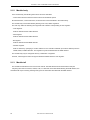
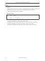
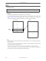
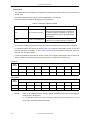
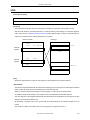
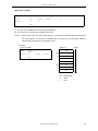
2.1.4
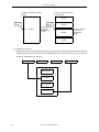
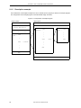
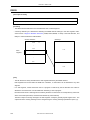
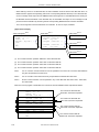
Overall configuration of source program
The overall configuration of a source module (source program) is as shown below.
Figure 2-2 Overall Configuration of Source Module
Control instruction(s) that have the
same function(s) as assembler option(s)
Special
control
instruction(s)
output by high-level programs such
as C compiler
Module header
Directive(s)
Module body
Control instruction(s)
Instruction(s)
Module tail
END directive
Examples of simple source module configurations are shown below.
Figure 2-3 Examples of Source Module Configurations
$ PROCESSOR ( f1166a0 )
$ PROCESSOR ( f1166a0 )
VECT
FLAG
CSEG
AT
0H
:
:
:
MAIN
CSEG
BSEG
:
:
:
WORK
DSEG
:
:
:
:
:
:
Module header
SUB
Module body
CSEG
:
:
:
END
END
User’s Manual U18546EJ1V0UM
Module tail
25
CHAPTER 2 HOW TO DESCRIBE SOURCE PROGRAMS
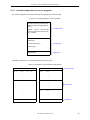
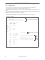
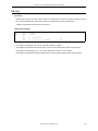
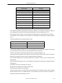
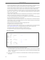
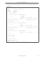
2.1.5
Description example
In this subsection, a description example of a source module (source program) is shown as a sample program.
The configuration of the sample program can be illustrated simply as follows.
Figure 2-4 Configuration of Sample Program
<Subroutine>
<Main routine>
NAME
SAMPM
NAME
SAMPS
DATA
DSEG
saddr
Variable definition
CODE
MAIN :
CSEG
DW
AT 0H
START
CSEG
CONVAH :
:
:
:
CSEG
START :
:
CALL
CALL
!CONVAH
:
:
:
:
:
:
RET
END
END
26
CSEG
SASC :
User’s Manual U18546EJ1V0UM
:
:
:
!SASC
RET
CHAPTER 2 HOW TO DESCRIBE SOURCE PROGRAMS
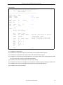
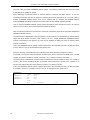
<Main routine>
NAME
SAMPM
; (1)
; ***********************************************
;
HEX -> ASCII Conversion Program
;
main-routine
; ***********************************************
PUBLIC
EXTRN
EXTRN
MAIN , START
CONVAH
_@STBEG
; (2)
; (3)
; (4) <-- Error
DATA
DSEG
HDTSA : DS
STASC : DS
AT
1
2
0FFE20H
; (5)
CODE
MAIN :
AT
START
0H
; (6)
CSEG
DW
CSEG
; (7)
START :
; chip initialize
MOVW
SP , #_@STBEG
MOV
MOVW
HDTSA , #1AH
HL , #LOWW ( HDTSA )
CALL
!CONVAH
MOVW
MOV
MOV
INCW
MOV
MOV
BR
DE , #LOWW ( STASC )
A , B
[ DE ] , A
DE
A , C
[ DE ] , A
$$
END
; set hex 2-code data in HL registor
; convert ASCII <- HEX
; output BC-register <- ASCII code
; set DE <- store ASCII code table
; (8)
(1) Declaration of module name
(2) Declaration of symbol referenced from another module as an external reference symbol
(3) Declaration of symbol defined in another module as an external reference symbol
(4) Declaration of stack solution symbol generated from the -s option of linker as an external reference symbol
(an error occurs if the -s option is not specified when linking)
(5) Declaration of the start of a data segment (to be located in saddr)
(6) Declaration of the start of a code segment (to be located as an absolute segment starting from address 0H)
(7) Declaration of the start of a code segment (meaning the end of the absolute segment)
(8) Declaration of the end of the module
User’s Manual U18546EJ1V0UM
27
CHAPTER 2 HOW TO DESCRIBE SOURCE PROGRAMS
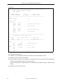
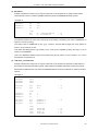
<Subroutine>
NAME
SAMPS
; (1)
; *************************************************************
;
HEX -> ASCII Conversion Program
;
sub-routine
;
;
input condition
: ( HL )
<- hex 2 code
;
output condition
: BC-register
<- ASCII 2 code
; *************************************************************
PUBLIC
CONVAH
CSEG
CONVAH :
XOR
ROL4
CALL
MOV
XOR
ROL4
CALL
MOV
RET
; (2)
; (3)
A , A
[ HL ]
!SASC
B , A
A , A
[ HL ]
!SASC
C , A
; hex upper code load (4)
; store result
; hex lower code load
; store result
; *************************************************************
;
subroutine
convert ASCII code
;
;
input
Acc ( lower 4bits )
<- hex code
;
output
Acc
<- ASCII code
; *************************************************************
SASC :
CMP
BC
ADD
A , #0AH
$SASC1
A , #07H
; check hex code > 9
ADD
RET
A , #30H
; bias ( +30H )
; bias ( +7H )
SASC1 :
END
; (5)
(1) Declaration of module name
(2) Declaration of symbol referenced from another module as an external definition symbol
(3) Declaration of the start of the code segment
(4) Since the ROL4 instruction is an instruction for the 78K0 Series, but not supported by the 78K0R Series,
specification of an assembler option (-compati) is required.
For the assembler option (-compati), refer to the RA78K0R Series Assembler Package Operation User's
Manual.
(5) Declaration of the end of the module
28
User’s Manual U18546EJ1V0UM
CHAPTER 2 HOW TO DESCRIBE SOURCE PROGRAMS
2.2
Description Method
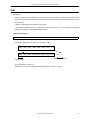
2.2.1
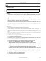
Configuration
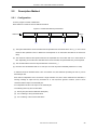
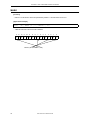
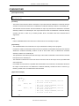
A source program consists of statements.
Each statement consists of the four fields shown below.
Figure 2-5 Fields That Make Up a Statement
Statement
Symbol field
Mnemonic field
(1)
Operand field
(2)
Comment field
(3)
[CR] LF
(4)
(1) The symbol field and the mnemonic field must be separated from each other with a colon ( : ) or one or more
blanks or tabs (Whether colons or blanks are used depends on an instruction described in the mnemonic
field).
(2) The mnemonic field and the operand field must be separated from each other with one or more blanks or
tabs. Depending on the instruction described in the mnemonic field, the operand field may not be required.
(3) The comment field if used must be preceded with a semicolon ( ; ).
(4) Each line must be delimited with an LF code (one CR code may exist immediately before the LF code).
- A statement must be described within a line. A maximum of 2,048 characters (including CR and LF) can be
described per line.
Each TAB or independent CR is counted as a single character. If 2,049 or more characters are described, a
warning message is output and any characters at or over 2,049 are ignored. However, 2,049 or more
characters will be output to the assembly list.
- An independent CR will not be output to the assembly list.
- The following lines may also be described:
(1) Dummy line (line without statement description)
(2) Line consisting of the symbol field alone
(3) Line consisting of the comment field alone
User’s Manual U18546EJ1V0UM
29
CHAPTER 2 HOW TO DESCRIBE SOURCE PROGRAMS
2.2.2
Character set
Characters that can be described in a source file are classified into the following three types:
- Language characters
- Character data
- Comment characters
(1) Language characters
Language characters are characters used to describe instructions in a source program.
The language character set includes alphabetic, numeric, and special characters.
Table 2-2 Alphanumeric Characters
Name
Characters
Numeric characters
Alphabetic
characters
0123456789
Uppercase letters
ABCDEFGHIJKLMNOPQRSTUVWXYZ
Lowercase letters
abcdefghijklmnopqrstuvwxyz
Table 2-3 Special Characters
Character
30
Name
Main Use
?
Question mark
Symbol equivalent to alphabetic characters
@
Circa
Symbol equivalent to alphabetic characters
_
Underscore
Symbol equivalent to alphabetic characters
Blank
Delimiter of each field
HT (09H)
Tab code
Character equivalent to blank
,
Comma
Delimiter of operands
:
Colon
Delimiter of labels
;
Semicolon
Symbol indicating the start of the Comment
field
CR (0DH)
Carriage return code
Symbol indicating the end of a line (ignored
in the assembler)
LF (0AH)
Line-feed code
Symbol indicating the end of a line
User’s Manual U18546EJ1V0UM
Delimiter
symbols
CHAPTER 2 HOW TO DESCRIBE SOURCE PROGRAMS
Table 2-3 Special Characters
Character
Name
Main Use
+
Plus sign
ADD operator or positive sign
-
Minus sign
SUBTRACT operator or negative sign
*
Asterisk
MULTIPLY operator
/
Slash
DIVIDE operator
.
Period
Bit position specifier
(, )
Left and right
parentheses
Symbols specifying the order of arithmetic
operations to be performed
<, >
Not Equal sign
Relational operators
=
Equal sign
Relational operator
'
Single quotation mark
- Symbol indicating the start or end of a character
constant
- Symbol indicating a complete macro parameter
$
Dollar sign
- Symbol indicating the location counter
- Symbol indicating the start of a control instruction
equivalent to an assembler option
- Symbol specifying relative addressing
&
Ampersand
Concatenating symbol (used in macro body)
#
Sharp sign
Symbol specifying immediate addressing
!
Exclamation point
Symbol specifying absolute addressing
[]
Brackets
Symbol specifying indirect addressing
Assembler
operators
(2) Character data
"Character data" refers to characters used to describe string constants, character strings, and control
instructions (TITLE, SUBTITLE, INCLUDE).
Caution 1
All characters except "00H" can be used (including kanji (2-byte characters); codes may be
different depending on the operating system). If "00H" has been described, an error occurs
and subsequent characters before the closing single quotation mark ( ' ) will be ignored.
Caution 2
If any illegal character has been described, the assembler will replace the illegal character with
"!" for output to the assembly list (an independent CR (0DH) code will not be output to the
assembly list).
Caution 3
With Windows, the assembler interprets code "1AH" as the end of the file (EOF) and thus the
code cannot be a part of the input data.
(3) Comment characters
"Comment characters" refers to characters used to describe a comment statement.
Caution Characters that can be used in a comment statement are the same as those in the character set for
character data. However, no error occurs even if code "00H" has been described. Instead, the
assembler will output the illegal character to the assembly list by replacing it with "!".
User’s Manual U18546EJ1V0UM
31
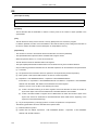
CHAPTER 2 HOW TO DESCRIBE SOURCE PROGRAMS
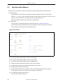
2.2.3
Symbol field
A symbol is described in the symbol field. The term "symbol" refers to a name given to numerical data or an
address.
By using symbols, the contents of a source program can be understood more easily.
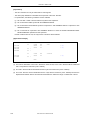
(1) Symbol types
Symbols are classified into the types shown below, depending on their use and method of definition.
Symbol Type
Use
Method of Definition
Name
Used as numerical data or an
address in a source program.
This type is described in the symbol
field of the EQU, SET, or DBIT directive.
Label
Used as address data in a source
program.
This type is defined by suffixing a colon
( : ) to a symbol.
External
reference name
Used to reference symbol defined by
a module by another module.
This type is described in the operand
field of the EXTRN or EXTBIT directive.
Segment name
Symbol used during linker operation
This type is defined in the symbol field
of the CSEG, DSEG, BSEG or ORG
directive.
Module name
Used during symbolic debugging
This type is described in the operand
field of the NAME directive.
Macro name
Used for macro reference in a source
program.
This type is described in the symbol
field of the MACRO directive.
Caution The four types of symbol, name, label, segment name, and macro name, can be described in the
symbol field.
32
User’s Manual U18546EJ1V0UM
CHAPTER 2 HOW TO DESCRIBE SOURCE PROGRAMS
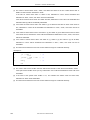
(2) Conventions of symbol description
All symbols must be described according to the following rules:
- A symbol must be made up of alphanumeric characters and special characters (?, @, and _) that can be
used as characters equivalent to alphabetic characters.
None of the numeric characters 0 to 9 can be used as the first character of a symbol.
- A symbol must be made up of not more than 256 characters. Characters in excess of the maximum
symbol length will be ignored.
- No reserved word can be used as a symbol.
Reserved words are indicated in Table A-2.
- The same symbol cannot be defined more than once.
However, a name defined with the SET directive can be redefined with the SET directive.
- The assembler distinguishes between lowercase and uppercase characters.
- When describing a label in the Symbol field, ":" (colon) must be described immediately after the label.
<Examples of correct symbol descriptions>
CODE01 CSEG
VAR01
EQU
LAB01 : DW
NAME
MAC1
MACRO
10H
0
SAMPLE
;
;
;
;
;
"CODE01" is a segment name.
"VAR01" is a name.
"LAB01" is a label.
"SAMPLE" is a module name.
"MAC1" is a macro name.
<Examples of incorrect symbol descriptions>
1ABC
EQU
3
LAB
MOV
A , R0
FLAG :
EQU
10H
;
;
;
;
;
No numeric character can be used as the 1st
character of a symbol.
"LAB" is a label and must be separated from
the Mnemonic field with a colon ( : ).
A colon ( : ) is not necessary in a name.
<Example of a symbol that is too long>
A123456789B12 to Y123456789Z123456
EQU
70H
; Character "6" in excess of the maximum symbol
257
; length (256 characters) are ignored.
; The symbol will be defined as
; "A123456789B12 to Y123456789Z12345".
<Example of a statement composed of a symbol only>
ABCD :
; "ABCD" will be defined as a label.
User’s Manual U18546EJ1V0UM
33
CHAPTER 2 HOW TO DESCRIBE SOURCE PROGRAMS
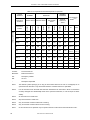
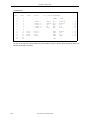
(3) Some cautions about symbols
The symbol "??RAnnnn (n = 0000 to FFFF)" is a symbol that is automatically replaced by the assembler
every time a local symbol is developed inside a macro body. Be careful not to define this symbol twice.
When a segment name is not specified by a segment definition directive, the assembler generates a
segment name automatically. These segments are shown below.
Duplicate segment name definition causes an error.
Segment Name
Directive
Relocation Attribute
?A0nnnnn(nnnnn = 00000 - FFFFF) ORG directive
(none)
?CSEG
UNIT
?CSEGUP
UNITP
?CSEGT0
CALLT0
?CSEGFX
FIXED
?CSEGSI
SECUR_ID
CSEG directive
?CSEGB
BASE
?CSEGP64
PAGE64KP
?CSEGU64
UNIT64KP
?CSEGMIP
MIRRORP
?CSEGOB0
OPT_BYTE
?DSEG
UNIT
?DSEGUP
UNITP
?DSEGS
SADDR
?DSEGSP
SADDRP
?DSEGBP
BASEP
?DSEGP64
PAGE64KP
?DSEGU64
UNIT64KP
?BSEG
34
DSEG directive
BSEG directive
User’s Manual U18546EJ1V0UM
UNIT
CHAPTER 2 HOW TO DESCRIBE SOURCE PROGRAMS
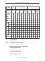
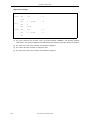
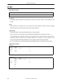
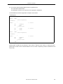
(4) Symbol attributes
All names and labels have both a value and an attribute.
A value refers to the value of defined numerical data or address data itself.
Segment names, module names, and macro names do not have a value.
The attribute of a symbol is called a symbol attribute and must be one of the eight types indicated in the following table.
Attribute
Type
Classification
Value
NUMBER
- Names to which numeric constants are
assigned
- Symbols defined with the EXTRN directive
- Numeric constants
Decimal representation: 0 to
1,048,575
Hexadecimal representation:
00000H to FFFFFH (unsigned)
ADDRESS
- Symbols defined as labels
- Names defined as labels with EQU and SET
directives
Decimal representation: 0 to
1,048,575
Hexadecimal representation:
00000H to FFFFFH
BIT
- Names defined as bit values
- Names within BSEG
- Symbols defined with the EXTBIT directive
0H to FFFFFH
SFR
Names defined as SFRs with the EQU directive
SFRP
Names defined as SFRs with the EQU directive
CSEG
Segment names defined with the CSEG directive
DSEG
Segment names defined with the DSEG directive
BSEG
Segment names defined with the BSEG directive
MODULE
Module names defined with the NAME directive
(A module name if not defined is created from the
primary name of the input source filename)
MACRO
Macro names defined with the MACRO directive
SFR area
These attribute types have no
value.
<Examples>
TEN
EQU
10H
ORG
START : MOV
80H
A , #10H
BIT1
0FFE20H.0
EQU
; Name "TEN" has attribute "NUMBER"
; and value "10H".
;
;
;
;
Label "START" has attribute "ADDRESS"
and value "80H".
Name "BIT1" has attribute "BIT"
and value "0FFE20H.0".
User’s Manual U18546EJ1V0UM
35
CHAPTER 2 HOW TO DESCRIBE SOURCE PROGRAMS
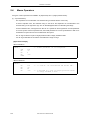
2.2.4
Mnemonic field
In the mnemonic field, a mnemonic instruction, a directive, or a macro reference is described.
With an instruction or directive requiring an operand or operands, the mnemonic field must be separated from
the operand field with one or more blanks or tabs.
However, with the first operand of an instruction that begins with "#", "$","!", or "[ ", the assembly will be executed
properly even if nothing exists between the mnemonic field and the first operand field.
<Examples of correct descriptions>
MOV
CALL
RET
A , #0H
!CONVAH
<Examples of incorrect descriptions>
MOVA
CALL
ZZZ
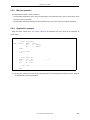
2.2.5
#0H
!CONVAH
; No blank exists between the mnemonic and operand fields.
; A blank exists within the mnemonic field.
; The 78K0R Series has no such instruction as "ZZZ".
Operand field
In the operand field, the data (operands) required for executing the instruction, directive, or macro reference is
described.
Depending on the instruction or directive, no operand is required in the operand field or two or more operands
must be described in the operand field.
When describing two or more operands, delimit each operand with a comma ( , ).
The following types of data can be described in the operand field:
- Constants (numeric constants and string constants)
- Character strings
- Register names
- Special characters ($, #, !, and [ ])
- Relocation attributes of segment definition directives
- Symbols
- Expressions
- Bit terms
The size and attribute of the required operand may be different depending on the instruction or directive. Refer to
"2.15 Characteristics of Operands" for the sizes and attributes of operands.
For the operand representation formats and description methods in the instruction set, see the user's manual of
the microcontroller for which software is being developed.
Each of the data types that can be described in the operand field is detailed below.
36
User’s Manual U18546EJ1V0UM
CHAPTER 2 HOW TO DESCRIBE SOURCE PROGRAMS
(1) Constants
A constant is a fixed value or data item and is also referred to as immediate data.
Constants are divided into numeric constants and character-string constants.
(a) Numeric constants
A binary, octal, decimal, or hexadecimal number can be described as a numeric constant.
The method of representing each numeric constant type is shown below.
A numeric constant will be processed as unsigned 32-bit data.
Value range: 0 < n < 0FFFFFFFFH
When describing a negative value, use the minus sign of the operator.
Constant
Method of Representation
Example
Binary constant
Character "B" or "Y" is suffixed to a numerical value.
1101B
1101Y
Octal constant
Character "O" or "Q" is suffixed to a numerical value.
74O
74Q
Decimal constant
A numerical value is described as is, or character "D" or
"T" is suffixed to a numerical value.
128
128D
128T
Hexadecimal constant
- Character "H" is suffixed to a numerical value.
- If the first character begins with "A", "B", "C", "D", "E",
or "F", "0" must be prefixed to the constant.
8CH
0A6H
(b) Character-string constants
A character-string constant is expressed by enclosing a string of characters from those shown in "2.2.2
Character set", in a pair of single quotation marks ( ' ).
As a result of an assembly process, the character-string constant is converted into 7-bit ASCII code with
the parity bit (MSB) set as "0".
The length of a string constant is 0 to 2 characters.
To use the single quotation mark itself as a string constant, the single quotation mark must be input
twice in succession.
<Examples of character-string constant descriptions>
'ab'
'A'
'A'''
' '
;
;
;
;
Represents
Represents
Represents
Represents
"6162H"
"0041H"
"4127H"
"0020H" (one blank)
(2) Character strings
A character string is expressed by enclosing a string of characters from those shown in "2.2.2 Character
set", in a pair of single quotation marks ( ' ). Character strings are mainly used for operands in the DB, CALL
directive and TITLE or SUBTITLE control instruction.
<Application examples of character strings>
MAS1 :
MAS2 :
CSEG
DB
DB
'YES'
'NO'
; Initializes with character string "YES".
; Initializes with character string "NO".
User’s Manual U18546EJ1V0UM
37
CHAPTER 2 HOW TO DESCRIBE SOURCE PROGRAMS
(3) Register names
The following registers can be described in the Operand field:
- General registers
- General register pairs
- Special function registers
General registers and general register pairs can be described with their absolute names (R0 to R7 and RP0
to RP3), as well as with their function names (X, A, B, C, D, E, H, L, AX, BC, DE, HL).
The register names that can be described in the operand field may differ depending on the type of
instruction. For details of the method of describing each register name, see the user's manual of each
device for which software is being developed.
(4) Special characters
Special characters that can be described in the operand field are shown below.
Special Character
Function
$
- Indicates the location address of the instruction having this operand (or the
1st byte of this address, in the case of addresses with a multiple-byte
instruction).
- Indicates a relative addressing mode for a branch instruction.
!
- Indicates an absolute addressing mode for a branch instruction.
- Indicates the specification of addr16 that allows all memory space to be
specified with an MOV instruction.
#
- Indicates immediate data.
[]
- Indicates indirect addressing mode.
<Application examples of special characters>
Address Source program
100
ADD
102
LOOP : INC
103
BR
105
BR
A , #10H
A
$$ - 1
!$ + 100H
; (1)
; (2)
(1) The second $ in the operand indicates address 103H. Describing "BR $ - 1" results in the same
operation.
(2) The second $ in the operand indicates address 105H. Describing "BR $ + 100H" results in the same
operation.
(5) Relocation attributes of segment definition directives
Relocation attributes can be described in the operand field.
For details of relocation attributes, refer to "3.2 Segment Definition Directives".
38
User’s Manual U18546EJ1V0UM
CHAPTER 2 HOW TO DESCRIBE SOURCE PROGRAMS
(6) Symbols
If a symbol is described in the operand field, an address (or value) allocated to that symbol becomes the
operand value.
<Application examples of symbols>
VALUE
EQU
MOV
1234H
A , #VALUE
; This description can be written as
; "MOV A , #1234H".
(7) Expressions
An expression is constants, $ (which indicates a location address), names, or labels connected with
operators.
The expression can be described where numeric values can be expressed as instruction operands.
For the expressions and operators, refer to "2.3 Expressions and Operators".
<Examples of expressions>
TEN
EQU
MOV
10H
A , #TEN - 5H
In this example, "TEN - 5H" is an expression.
In this expression, the name and numeric constant are connected with a - (minus) operator. The value of the
expression is "BH".
Therefore, this description can be rewritten as "MOV A , #0BH".
(8) Bit terms
A bit term can be obtained by the bit position specifier.
For details of bit terms, refer to 2.14 Bit Position Specifier.
<Examples of bit terms>
CLR1
SET1
CLR1
A.5
1 + 0FFE30H.3
0FFE40H.4 + 2
; The operand value is 0FFE31H.3.
; The operand value is 0FFE40H.6.
User’s Manual U18546EJ1V0UM
39
CHAPTER 2 HOW TO DESCRIBE SOURCE PROGRAMS
2.2.6
Comment field
In the comment field, comments or remarks may be described following the input of a semicolon ( ; ).
The comment field is from a semicolon to the line-feed code of that line or EOF.
By describing a comment statement in the comment field, an easy-to-understand source program can be
created.
The comment statement in the comment field is not subject to assembler operation (i.e., conversion into machine
language) but will be output without change on an assembly list.
Characters that can be described in the comment field are those shown in "2.2.2 Character set".
<Examples of comments>
NAME
SAMPM
; *****************************************
;
HEX -> ASCII Conversion Program
;
main-routine
; *****************************************
PUBLIC
EXTRN
EXTRN
MAIN , START
CONVAH
@STBEG
DATA
HDTSA:
STASC:
DSEG
DS
DS
saddr
1
2
CODE
MAIN :
CSEG
DW
AT 0H
START
Lines consisting of comment field only
CSEG
START :
; chip initialize
MOVW
SP , #_@STBEG
MOV
MOVW
HDTSA , #1AH
HL , #HDTSA
CALL
!CONVAH
; convert ASCII <- HEX
; output BC-register <- ASCII code
MOVW
MOV
MOV
INCW
MOV
MOV
BR
DE , #STASC
A , B
[ DE ] , A
DE
A , C
[ DE ] , A
$$
; set DE <- store ASCII code table
; set hex 2-code data in HL register
END
40
Lines consisting of comment field
only
User’s Manual U18546EJ1V0UM
Lines in
which
comments
are
described
in comment field
CHAPTER 2 HOW TO DESCRIBE SOURCE PROGRAMS
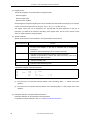
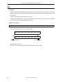
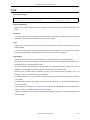
2.3
Expressions and Operators
An expression is a symbol, constant, location address (indicated by $) or bit term, an operator combined with one
of the above, or a combination of operators.
Elements of an expression other than the operators are called terms, and are referred to as the 1st term, 2nd
term, and so forth from left to right, in the order of their description.
Operators are available in the types shown in Table 2-4, and the order of their precedence in calculation has
been predetermined as shown in Table 2-5.
Parentheses "( )" are used to change the order in which calculations are performed.
<Example>
MOV
A , #5 * ( SYM + 1 )
; (1)
In (1) above, "5 * ( SYM + 1 )" is an expression. "5" is the 1st term of the expression and "SYM" and "1" are the
2nd and 3rd terms respectively. "*", "+", and "( )" are operators.
Table 2-4 Types of Operators
Type of Operator
Operators
Arithmetic Operators
+, -, *, /, MOD, + sign, - sign
Logical Operators
NOT, AND, OR, XOR
Relational Operators
EQ (=), NE (< >), GT (>), GE (>=), LT (<), LE (<=)
Shift Operators
SHR, SHL
Byte-Separating Operators
HIGH, LOW
Word-Separating Operators
HIGHW, LOWW
Special Operators
DATAPOS, BITPOS, MASK
Other Operator
()
The above operators can also be divided into unary operators, special unary operators, binary operators, N-ary
operators, and other operators.
Unary operators
+ sign, - sign, NOT, HIGH, LOW, HIGHW, LOWW
Special unary operators
DATAPOS, BITPOS
Binary operators
+, -, *, /, MOD, AND, OR, XOR, EQ (or =), NE (or < >), GT (or >), GE (or
>=), LT (or <), LE (or <=), SHR, SHL
N-ary operators
MASK
Other operators
()
User’s Manual U18546EJ1V0UM
41
CHAPTER 2 HOW TO DESCRIBE SOURCE PROGRAMS
Table 2-5 Order of Precedence of Operators
Priority
Priority Level
Operators
Higher
1
+ sign, - sign, NOT, HIGH, LOW, HIGHW, LOWW, DATAPOS, BITPOS, MASK
2
*, /, MOD, SHR, SHL
3
+, -
4
AND
5
OR, XOR
6
EQ (or =), NE (or < >), GT (or >), GE (or >=), LT (or <), LE (or <=)
Lower
Operations on expressions are performed according to the following rules:
- Operations are performed according to the order of precedence given to each operator.
If two or more operators of the same order of precedence exist in an expression, the operation designated
by the leftmost operator will be carried out. In the case of unary operators, the operation will be performed
from right to left.
- An expression in parentheses is carried out before expressions outside the parentheses.
- Operations between two or more unary operators are allowed.
Examples:
1 = - - 1 == 1
-1 = - + 1 = -1
- Expressions are calculated within 32 bits, without signs.
If an overflow occurs in operation due to an expression exceeding 32 bits, the overflowed value is ignored.
- If a constant exceeds 32 bits, an error occurs and the value of the result will be regarded as 0 for calculation.
- In division, the decimal fraction part of the result will be truncated.
If the divisor is 0, an error occurs, and the result will be 0.
- Two's compliments are used to represent negative values.
- The evaluated values for external reference symbols are zero during assemby (the evaluation value is
determined during linking).
- The result obtained from the expression described in the operand field must satisfy the instruction's
requirement.
If a relocatable expression or expression that uses an external reference is described for an instruction that
requests 8-bit operands, the object is generated from the lower 8-bit values, and required relocation
information is output in 16-bit units. The linker then checks whether the determined value is within the 8-bit
range. If overflows, an error occurs at linking.
If an absolute expression is described, the assembler determines the value and checks whether the value is
within the requested range is checked.
For example, the MOV instruction requests 8-bit operands, so it must fit within the range of 0H to 0FFH.
42
User’s Manual U18546EJ1V0UM
CHAPTER 2 HOW TO DESCRIBE SOURCE PROGRAMS
<Examples of correct descriptions>
MOV
MOV
A , #'2*' AND 0FH
A , #4 * 8 * 8 - 1
<Examples of incorrect descriptions>
MOV
MOV
A , #'2*.
A , #4 * 8 * 8
<Examples of evaluation>
Expression
Evaluation Value
2+4*5
22
(2+3)*4
20
10 / 4
2
0-1
0FFFFFFFFH
-1 > 1
00H (False)
EXTNote + 1
1
Note EXT : External reference symbols
User’s Manual U18546EJ1V0UM
43
CHAPTER 2 HOW TO DESCRIBE SOURCE PROGRAMS
2.4
Arithmetic Operators
The following arithmetic operators are available.
- +
- - *
- /
- MOD
- + sign
- - sign
44
User’s Manual U18546EJ1V0UM
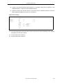
CHAPTER 2 HOW TO DESCRIBE SOURCE PROGRAMS
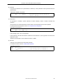
+
[Function]
- Returns the sum of the values of the 1st and 2nd terms of an expression.
[Application Example]
ORG
START : BR
100H
!$ + 6
; (a)
- The BR instruction causes a jump to "current location address plus 6", namely, to address "100H + 6H =
106H".
Therefore, (a) in the above example can also be described as: START : BR !106H
User’s Manual U18546EJ1V0UM
45
CHAPTER 2 HOW TO DESCRIBE SOURCE PROGRAMS
[Function]
- Returns the result of subtraction of the 2nd-term value from the 1st-term value.
[Application Example]
BACK :
ORG
BR
100H
BACK - 6H
; (a)
- The BR instruction causes a jump to "address assigned to BACK minus 6", namely, to address "100H - 6H =
0FAH".
Therefore, (a) in the above example can also be described as: BACK : BR !0FAH
46
User’s Manual U18546EJ1V0UM
CHAPTER 2 HOW TO DESCRIBE SOURCE PROGRAMS
*
[Function]
- Returns the result of multiplication (product) between the values of the 1st and 2nd terms of an expression.
[Application Example]
TEN
EQU
MOV
10H
A , #TEN * 3
; (a)
- With the EQU directive, the value "10H" is defined in the name "TEN".
"#" indicates immediate data. The expression "TEN * 3" is the same as "10H * 3" and returns the value
"30H".
Therefore, (a) in the above expression can also be described as: MOV A , #30H
User’s Manual U18546EJ1V0UM
47
CHAPTER 2 HOW TO DESCRIBE SOURCE PROGRAMS
/
[Function]
- Divides the value of the 1st term of an expression by the value of its 2nd term and returns the integer part of
the result.
The decimal fraction part of the result will be truncated. If the divisor (2nd term) of a division operation is 0,
an error occurs.
[Application Example]
MOV
A , #256 / 50
; (a)
- The result of the division "256 / 50" is 5 with remainder 6.
The operator returns the value "5" that is the integer part of the result of the division.
Therefore, (a) in the above expression can also be described as: MOV A , #5
48
User’s Manual U18546EJ1V0UM
CHAPTER 2 HOW TO DESCRIBE SOURCE PROGRAMS
MOD
[Function]
- Obtains the remainder in the result of dividing the value of the 1st term of an expression by the value of its
2nd term.
An error occurs if the divisor (2nd term) is 0.
A blank is required before and after the MOD operator.
[Application Example]
MOV
A , #256 MOD 50
; (a)
- The result of the division "256 / 50" is 5 with remainder 6.
The MOD operator returns the remainder 6.
Therefore, (a) in the above expression can also be described as: MOV A , #6.
User’s Manual U18546EJ1V0UM
49
CHAPTER 2 HOW TO DESCRIBE SOURCE PROGRAMS
+ sign
[Function]
- Returns the value of the term of an expression without change.
[Application Example]
FIVE
EQU
+5
- The value "5" of the term is returned without change.
The value "5" is defined in name "FIVE" with the EQU directive.
50
User’s Manual U18546EJ1V0UM
CHAPTER 2 HOW TO DESCRIBE SOURCE PROGRAMS
- sign
[Function]
- Returns the value of the term of an expression by the two's complement.
[Application Example]
NO
EQU
-1
- -1 becomes the two's complement of 1.
The two's complement of binary 0000 0000 0000 0000 0000 0000 0000 0001 becomes:
1111 1111 1111 1111 1111 1111 1111 1111
Therefore, with the EQU directive, the value "0FFFFFFFFH" is defined in the name "NO".
User’s Manual U18546EJ1V0UM
51
CHAPTER 2 HOW TO DESCRIBE SOURCE PROGRAMS
2.5
Logical Operators
The following logical operators are available.
- NOT
- AND
- OR
- XOR
52
User’s Manual U18546EJ1V0UM
CHAPTER 2 HOW TO DESCRIBE SOURCE PROGRAMS
NOT
[Function]
- Negates the value of the term of an expression on a bit-by-bit basis and returns the result.
A blank is required between the NOT operator and the term.
[Application Example]
MOVW
AX , #LOWW ( NOT 3H )
; (a)
- Logical negation is performed on "3H" as follows:
NOT)
0000
0000
0000
0000
0000
0000
0000
0011
1111
1111
1111
1111
1111
1111
1111
1100
0FFFFFFFCH is returned.
Therefore, (a) can also be described as: MOVW AX , #LOWW #0FFFFFFFCH
User’s Manual U18546EJ1V0UM
53
CHAPTER 2 HOW TO DESCRIBE SOURCE PROGRAMS
AND
[Function]
- Performs an AND (logical product) operation between the value of the 1st term of an expression and the
value of its 2nd term on a bit-by-bit basis and returns the result.
A blank is required before and after the AND operator.
[Application Example]
MOV
A , #6FAH AND 0FH
; (a)
- AND operation is performed between the two values "6FAH" and "0FH" as follows:
AND)
0000
0000
0000
0000
0000
0110
1111
1010
0000
0000
0000
0000
0000
0000
0000
1111
0000
0000
0000
0000
0000
0000
0000
1010
The result "0AH" is returned. Therefore, (a) in the above expression can also be described as: MOV A ,
#0AH
54
User’s Manual U18546EJ1V0UM
CHAPTER 2 HOW TO DESCRIBE SOURCE PROGRAMS
OR
[Function]
- Performs an OR (Logical sum) operation between the value of the 1st term of an expression and the value
of its 2nd term on a bit-by-bit basis and returns the result.
A blank is required before and after the OR operator.
[Application Example]
MOV
A , #0AH OR 1101B
; (a)
- OR operation is performed between the two values "0AH" and "1101B" as follows:
OR)
0000
0000
0000
0000
0000
0000
0000
1010
0000
0000
0000
0000
0000
0000
0000
1101
0000
0000
0000
0000
0000
0000
0000
1111
The result "0FH" is returned.
Therefore, (a) in the above expression can also be described as: MOV A , #0FH
User’s Manual U18546EJ1V0UM
55
CHAPTER 2 HOW TO DESCRIBE SOURCE PROGRAMS
XOR
[Function]
- Performs an Exclusive-OR operation between the value of the 1st term of an expression and the value of its
2nd term on a bit-by-bit basis and returns the result. A blank is required before and after the XOR operator.
[Application Example]
MOV
A , #9AH XOR 9DH
; (a)
- XOR operation is performed between the two values "9AH" and "9DH" as follows:
XOR)
0000
0000
0000
0000
0000
0000
1001
1010
0000
0000
0000
0000
0000
0000
1001
1101
0000
0000
0000
0000
0000
0000
0000
0111
The result "7H" is returned.
Therefore, (a) in the above expression can also be described as: MOV A , #7H
56
User’s Manual U18546EJ1V0UM
CHAPTER 2 HOW TO DESCRIBE SOURCE PROGRAMS
2.6
Relational Operators
The following relational operators are available.
- EQ (=)
- NE (< >)
- GT (>)
- GE (>=)
- LT (<)
- LE (<=)
User’s Manual U18546EJ1V0UM
57
CHAPTER 2 HOW TO DESCRIBE SOURCE PROGRAMS
EQ (=)
[Function]
- Returns 0FFH (True) if the value of the 1st term of an expression is equal to the value of its 2nd term, and
00H (False) if both values are not equal.
A blank is required before and after the EQ operator.
[Application Example]
A1
A2
EQU
EQU
12C4H
12C0H
MOV
MOV
A , #A1 EQ ( A2 + 4H )
X , #A1 EQ A2
; (a)
; (b)
- In (a) above, the expression "A1 EQ ( A2 + 4H )" becomes "12C4H EQ ( 12C0H + 4H )".
The operator returns 0FFH because the value of the 1st term is equal to the value of the 2nd term.
- In (b) above, the expression "A1 EQ A2" becomes "12C4H EQ 12C0H".
The operator returns 00H because the value of the 1st term is not equal to the value of the 2nd term.
58
User’s Manual U18546EJ1V0UM
CHAPTER 2 HOW TO DESCRIBE SOURCE PROGRAMS
NE (< >)
[Function]
- Returns 0FFH (True) if the value of the 1st term of an expression is not equal to the value of its 2nd term,
and 00H (False) if both values are equal.
A blank is required before and after the NE operator.
[Application Example]
A1
A2
EQU
EQU
5678H
5670H
MOV
MOV
A , #A1 NE A2
A , #A1 NE ( A2 + 8H )
; (a)
; (b)
- In (a) above, the expression "A1 NE A2" becomes "5678H NE 5670H".
The operator returns 0FFH because the value of the 1st term is not equal to the value of the 2nd term.
- In (b) above, the expression "A1 NE ( A2 + 8H )" becomes "5678H NE ( 5670H + 8H )".
The operator returns 00H because the value of the 1st term is equal to the value of the 2nd term.
User’s Manual U18546EJ1V0UM
59
CHAPTER 2 HOW TO DESCRIBE SOURCE PROGRAMS
GT (>)
[Function]
- Returns 0FFH (True) if the value of the 1st term of an expression is greater than the value of its 2nd term,
and 00H (False) if the value of the 1st term is equal to or less than the value of the 2nd term.
A blank is required before and after the GT operator.
[Application Example]
A1
A2
EQU
EQU
1023H
1013H
MOV
MOV
A , #A1 GT A2
X , #A1 GT ( A2 + 10H )
; (a)
; (b)
- In (a) above, the expression "A1 GT A2" becomes "1023H GT 1013H".
The operator returns 0FFH because the value of the 1st term is greater than the value of the 2nd term.
- In (b) above, the expression "A1 GT ( A2 + 10H )" becomes "1023H GT ( 1013H + 10H )".
The operator returns 00H because the value of the 1st term is equal to the value of the 2nd term.
60
User’s Manual U18546EJ1V0UM
CHAPTER 2 HOW TO DESCRIBE SOURCE PROGRAMS
GE (>=)
[Function]
- Returns 0FFH (True) if the value of the 1st term of an expression is greater than or equal to the value of its
2nd term, and 00H (False) if the value of the 1st term is less than the value of the 2nd term.
A blank is required before and after the GE operator.
[Application Example]
A1
A2
EQU
EQU
2037H
2015H
MOV
MOV
A , #A1 GE A2
X , #A1 GE ( A2 + 23H )
; (a)
; (b)
- In (a) above, the expression "A1 GE A2" becomes "2037H GE 2015H".
The operator returns 0FFH because the value of the 1st term is greater than the value of the 2nd term.
- In (b) above, the expression "A1 GE ( A2 + 23H )" becomes "2037H GE ( 2015H + 23H )".
The operator returns 00H because the value of the 1st term is less than the value of the 2nd term.
User’s Manual U18546EJ1V0UM
61
CHAPTER 2 HOW TO DESCRIBE SOURCE PROGRAMS
LT (<)
[Function]
- Returns 0FFH (True) if the value of the 1st term of an expression is less than the value of its 2nd term, and
00H (False) if the value of the 1st term is equal to or greater than the value of the 2nd term.
A blank is required before and after the LT operator.
[Application Example]
A1
A2
EQU
EQU
1000H
1020H
MOV
MOV
A , #A1 LT A2
X , # ( A1 + 20H ) LT A2
; (a)
; (b)
- In (a) above, the expression "A1 LT A2" becomes "1000H LT 1020H".
The operator returns 0FFH because the value of the 1st term is less than the value of the 2nd term.
- In (b) above, the expression "( A1 + 20H ) LT A2" becomes "( 1000H + 20H ) LT 1020H".
The operator returns 00H because the value of the 1st term is equal to the value of the 2nd term.
62
User’s Manual U18546EJ1V0UM
CHAPTER 2 HOW TO DESCRIBE SOURCE PROGRAMS
LE (<=)
[Function]
- Returns 0FFH (True) if the value of the 1st term of an expression is less than or equal to the value of its 2nd
term, and 00H (False) if the value of the 1st term is greater than the value of the 2nd term.
A blank is required before and after the LE operator.
[Application Example]
A1
A2
EQU
EQU
103AH
1040H
MOV
MOV
A , #A1 LE A2
X , # ( A1 + 7H ) LE A2
; (a)
; (b)
- In (a) above, the expression "A1 LE A2" becomes "103AH LE 1040H".
The operator returns 0FFH because the value of the 1st term is less than the value of the 2nd term.
- In (b) above, the expression "( A1 + 7H ) LE A2" becomes "( 103AH + 7H ) LE 1040H".
The operator returns 00H because the value of the 1st term is greater than the value of the 2nd term.
User’s Manual U18546EJ1V0UM
63
CHAPTER 2 HOW TO DESCRIBE SOURCE PROGRAMS
2.7
Shift Operators
The following shift operators are available.
- SHR
- SHL
64
User’s Manual U18546EJ1V0UM
CHAPTER 2 HOW TO DESCRIBE SOURCE PROGRAMS
SHR
[Function]
- Returns a value obtained by shifting the value of the 1st term of an expression to the right the number of bits
specified by the value of the 2nd term. Zeros equivalent to the specified number of bits shifted move into the
high-order bits.
A blank is required before and after the SHR operator.
If the number of shifted bits is 0, the value of the first term is returned as is. If the number of shifted bits
exceeds 32, the space is automatically filled with zeros.
[Application Example]
MOV
A , #01AFH SHR 5
; (a)
- This operator shifts the value "01AFH" to the right by 5 bits.
0000
0000
0000
0000
0000
0001
1010
1111
0000
0000
0000
0000
0000
0000
0000
1101
0111
1
Right-shifted by 5 bits.
0's are inserted.
The value "000DH" is returned.
Therefore, (a) in the above example can also be described as: MOV A , #0DH
User’s Manual U18546EJ1V0UM
65
CHAPTER 2 HOW TO DESCRIBE SOURCE PROGRAMS
SHL
[Function]
- Returns a value obtained by shifting the value of the 1st term of an expression to the left the number of bits
specified by the value of the 2nd term. Zeros equivalent to the specified number of bits shifted move into the
low-order bits.
A blank is required before and after the SHL operator.
If the number of shifted bits is 0, the value of the first term is returned as is. If the number of shifted bits
exceeds 32, the space is automatically filled with zeros.
[Application Example]
MOV
A , #21H SHL 2
; (a)
- This operator shifts the value "21H" to the left by 2 bits.
00
0000
0000
0000
0000
0000
0000
0010
0001
0000
0000
0000
0000
0000
0000
1000
0100
Left-shifted by 2 bits.
0's are inserted.
The value "84H" is returned.
Therefore, (a) in the above example can also be described as: MOV A , #84H
66
User’s Manual U18546EJ1V0UM
CHAPTER 2 HOW TO DESCRIBE SOURCE PROGRAMS
2.8
Byte-Separating Operators
The following byte-separating operators are available.
- HIGH
- LOW
User’s Manual U18546EJ1V0UM
67
CHAPTER 2 HOW TO DESCRIBE SOURCE PROGRAMS
HIGH
[Function]
- Returns the high-order 8-bit value of a term.
A blank is required between the HIGH operator and the term.
[Application Example]
MOV
A , #HIGH 1234H
; (a)
- By executing a MOV instruction, this operator returns the high-order 8-bit value "12H" of the expression
"1234H".
Therefore, (a) in the above example can also be described as: MOV A , #12H
[Remark]
- A HIGH operation for an SFR name is performed, using either of the following description methods.
HIGHΔSFR-name
Or,
HIGH[Δ]([Δ]SFR-name[Δ])
The result obtained from the operation is an operand of the absolute NUMBER attribute.
No other operations can be performed for the SFR name.
<Example>
Symbol field
Mnemonic field
MOV
MOV
MOV
68
Operand field
R0 , #HIGH PM0
R1 , #HIGH PM1 + 1H
;
;
R1 , #HIGH ( PM1 + 1H ) ;
;
;
;
;
User’s Manual U18546EJ1V0UM
Equivalent to
#( HIGH PM1 ) + 1
An error is returned
because operands other
than HIGH, LOW, HIGHW,
and LOWW are specified
as the SFR name
CHAPTER 2 HOW TO DESCRIBE SOURCE PROGRAMS
LOW
[Function]
- Returns the low-order 8-bit value of a term.
A blank is required between the LOW operator and the term.
[Application Example]
MOV
A , #LOW 1234H
; (b)
- By executing a MOV instruction, this operator returns the low-order 8-bit value "34H" of the expression
"1234H".
Therefore, (b) in the above example can also be described as: MOV A , #34H
[Remark]
- A LOW operation for an SFR name is performed, using either of the following description methods.
LOWΔSFR-name
Or,
LOW[Δ]([Δ]SFR-name[Δ])
The result obtained from the operation is an operand of the absolute NUMBER attribute.
No other operations can be performed for the SFR name.
<Example>
Symbol field
Mnemonic field
MOV
MOV
Operand field
R0 , #LOW PM0
R1 , #LOW PM1 + 1H
MOV
R1 , #LOW
;
;
( PM1 + 1H ) ;
;
;
;
;
User’s Manual U18546EJ1V0UM
Equivalent to
#( LOW PM1 ) + 1
An error is returned
because operands other
than HIGH, LOW, HIGHW,
and LOWW are specified
as the SFR name
69
CHAPTER 2 HOW TO DESCRIBE SOURCE PROGRAMS
2.9
Word-Separating Operators
The following word-separating operators are available.
- HIGHW
- LOWW
70
User’s Manual U18546EJ1V0UM
CHAPTER 2 HOW TO DESCRIBE SOURCE PROGRAMS
HIGHW
[Function]
- Returns the high-order 8-bit value of a term.
A blank is required between the HIGHW operator and the term.
[Application Example]
MOVW
AX , #HIGHW
12345678H
; (a)
MOV
MOVW
ES , #HIGHW
AX , ES:!LAB
LAB
; (b)
- By executing a MOVW instruction, this operator returns the high-order 16-bit value "1234H" of the
expression "12345678H".
Therefore, (a) in the above example can also be described as: MOVW AX , #1234H
- By executing the MOV instruction on line (b), the higher address of label LAB is set to the ES register.
[Remark]
- A HIGHW operation for an SFR name is performed, using either of the following description methods.
HIGHWΔSFR-name
Or,
HIGHW[Δ]([Δ]SFR-name[Δ])
The result obtained from the operation is an operand of the absolute NUMBER attribute.
No other operations can be performed for the SFR name.
<Example>
Symbol field
Mnemonic field
MOVW
MOVW
MOVW
Operand field
RP0 , #HIGHW PM0
RP1 , #HIGHW PM1 + 1H
;
;
RP1 , #HIGHW ( PM1 + 1H ) ;
;
;
;
;
;
;
User’s Manual U18546EJ1V0UM
Equivalent to
#( HIGHW PM1 ) + 1
An error is
returned because
operands other than
HIGH, LOW, HIGHW,
and LOWW are
specified as the SFR
name
71
CHAPTER 2 HOW TO DESCRIBE SOURCE PROGRAMS
LOWW
[Function]
- Returns the low-order 8-bit value of a term.
A blank is required between the LOW operator and the term.
[Application Example]
MOVW
A , #LOWW 12345678H
; (a)
- By executing a MOV instruction, this operator returns the low-order 16-bit value "5678H" of the expression
"12345678H".
Therefore, (a) in the above example can also be described as: MOVW AX , #5678H
[Remark]
- A LOWW operation for an SFR name is performed, using either of the following description methods.
LOWWΔSFR-name
Or,
LOWW[Δ]([Δ]SFR-name[Δ])
The result obtained from the operation is an operand of the absolute NUMBER attribute.
No other operations can be performed for the SFR name.
<Example>
Symbol field
72
Mnemonic field
MOVW
MOVW
Operand field
RP0 , #LOWW PM0
RP1 , #LOWW PM1 + 1H
MOVW
RP1 , #LOWW ( PM1 + 1H )
User’s Manual U18546EJ1V0UM
;
;
;
;
;
;
;
;
;
Equivalent to
#( LOWW PM1 ) + 1
An error is
returned because
operands other than
HIGH, LOW, HIGHW,
and LOWW are
specified as the SFR
name
CHAPTER 2 HOW TO DESCRIBE SOURCE PROGRAMS
2.10
Special Operators
The following special operators are available.
- DATAPOS
- BITPOS
- MASK
User’s Manual U18546EJ1V0UM
73
CHAPTER 2 HOW TO DESCRIBE SOURCE PROGRAMS
DATAPOS
[Function]
- Returns the address portion (byte address) of a bit symbol.
[Application Example]
SYM
EQU
0FE68H.6
MOV
A , !DATAPOS SYM
; (a)
- An EQU directive defines the name "SYM" with a value of 0FE68H.6.
"DATAPOS SYM" represents "DATAPOS 0FE68H.6", and "0FE68H" is returned.
Therefore, (a) in the above example can also be described as: MOV A , !0FE68H
74
User’s Manual U18546EJ1V0UM
CHAPTER 2 HOW TO DESCRIBE SOURCE PROGRAMS
BITPOS
[Function]
- Returns the bit portion (bit position) of a bit symbol.
[Application Example]
SYM
EQU
0FE68H.6
CLR1
[ HL ].BITPOS SYM
- An EQU directive defines the name "SYM" with a value of 0FE68H.6.
"BITPOS.SYM" represents "BITPOS 0FE68H.6", and "6" is returned.
A CLR1 instruction clears [ HL ].6 to 0.
User’s Manual U18546EJ1V0UM
75
CHAPTER 2 HOW TO DESCRIBE SOURCE PROGRAMS
MASK
[Function]
- Returns a 16-bit value in which the specified bit position is 1 and all others are set to 0.
[Application Example]
MOVW
AX , #MASK ( 0 , 3 , 0FE00H.7 , 15 )
- A MOVW instruction returns the value "8089H".
F
E
D
C
B
A
9
8
7
6
5
4
3
2
1
0
1
0
0
0
0
0
0
0
1
0
0
0
1
0
0
1
MASK ( 0 , 3 , 0FE00H.7 , 15 )
76
User’s Manual U18546EJ1V0UM
CHAPTER 2 HOW TO DESCRIBE SOURCE PROGRAMS
2.11
Other Operator
The following other operator is available.
- ()
User’s Manual U18546EJ1V0UM
77
CHAPTER 2 HOW TO DESCRIBE SOURCE PROGRAMS
()
[Function]
- Causes an operation in parentheses to be performed prior to operations outside the parentheses.
This operator is used to change the order of precedence of other operators.
If parentheses are nested at multiple levels, the expression in the innermost parentheses will be calculated
first.
[Application Example]
MOV
A , # ( 4 + 3 ) * 2
(4+3)*2
(1)
(2)
Calculations are performed in the order of expressions (1), (2) and the value "14" is returned as a result.
If parentheses are not used,
4+3*2
(1)
(2)
Calculations are performed in the order (1), (2) shown above, and the value "10" is returned as a result.
See Table 2-5, for the order of precedence of operators.
78
User’s Manual U18546EJ1V0UM
CHAPTER 2 HOW TO DESCRIBE SOURCE PROGRAMS
2.12
Restrictions on Operations
The operation of an expression is performed by connecting terms with operator(s). Elements that can be
described as terms include constants, $, names, and labels. Each term has a relocation attribute and a symbol
attribute.
Depending on the types of relocation attribute and symbol attribute inherent in each term, operators that can
work on the term are limited. Therefore, when describing an expression, it is important to pay attention to the
relocation attribute and symbol attribute of each of the terms constituting the expression.
2.12.1 Operators and relocation attributes
As previously mentioned, each of the terms that constitute an expression has a relocation attribute and symbol
attribute.
Terms can be divided into three types when classified by their relocation attributes: Absolute terms, relocatable
terms, and external reference terms.
Types of relocation attributes in operations, the nature of each attribute, and terms applicable to each attribute
are shown below.
Table 2-6 Types of Relocation Attributes
Type
Nature
Applicable Terms
Absolute term
Term whose value and
constant are determined at
assembly time
- Constants
- Labels defined within an absolute segment
- $ indicating the location address defined within
an absolute segment
- Names defined with constants, the above
labels, the above $, or absolute values
Relocatable term
Term whose value is not
determined at assembly time
- Labels defined within a relocatable segment
- $ indicating the location address defined within
a relocatable segment
- Names defined with a relocatable symbol
External reference
termNote
Term that externally references
the symbol of another module
- Labels defined with the EXTRN directive
- Names defined with the EXTBIT directive
Note The following 6 operators can work on external reference terms: "+", "-", "HIGH", "LOW", "HIGHW",
"LOWW",. Only one external reference symbol can be described in an expression. In this case, the
external reference symbol must be connected with a "+" operator.
Combinations of the type of operator and terms on which each operator can work are shown below.
User’s Manual U18546EJ1V0UM
79
CHAPTER 2 HOW TO DESCRIBE SOURCE PROGRAMS
Table 2-7 Combinations of Terms and Operators by Relocation Attribute (Relocatable Terms)
Relocation Attribute of Term
Type of Operator
80
X: ABS
Y: ABS
X: ABS
Y: REL
X: REL
Y: ABS
X: REL
Y: REL
X+Y
A
R
R
-
X-Y
A
-
R
ANote 1
X*Y
A
-
-
-
X/Y
A
-
-
-
X MOD Y
A
-
-
-
X SHL Y
A
-
-
-
X SHR Y
A
-
-
-
X EQ Y
A
-
-
ANote 1
X LT Y
A
-
-
ANote 1
X LE Y
A
-
-
ANote 1
X GT Y
A
-
-
ANote 1
X GE Y
A
-
-
ANote 1
X NE Y
A
-
-
ANote 1
X AND Y
A
-
-
-
X OR Y
A
-
-
-
X XOR Y
A
-
-
-
NOT X
A
A
-
-
+X
A
A
R
R
-X
A
A
-
-
HIGH X
A
A
RNote 2
RNote 2
LOW X
A
A
RNote 2
RNote 2
HIGHW X
A
A
RNote 2
RNote 2
LOWW X
A
A
RNote 2
RNote 2
MASK ( X )
A
A
-
-
DATAPOS X.Y
A
-
-
-
BITPOS X.Y
A
-
-
-
MASK ( X.Y )
A
-
-
-
DATAPOS X
A
A
R
R
BITPOS X
A
A
A
A
User’s Manual U18546EJ1V0UM
CHAPTER 2 HOW TO DESCRIBE SOURCE PROGRAMS
ABS:
Absolute term
REL:
Relocatable term
A:
The result of the operation becomes an absolute term.
R:
The result of the operation becomes a relocatable term.
-:
The operation cannot be performed.
Note 1
The operation can only be performed if X and Y are defined within the same segment, and not
relocatable terms on which HIGH, LOW, HIGHW, LOWW, DATAPOS are operated.
Note 2
The operation can only be performed if X and Y are not relocatable terms on which HIGH, LOW,
HIGHW, LOWW, DATAPOS are operated.
The following 6 operators can work on external reference terms: "+", "-", "HIGH", "LOW", "HIGHW", and
"LOWW" (however, note that only one external reference term can be described in an expression).
Combinations of the types of operators and external reference terms on which each operator can work
areclassified according to relocation attributes in the following table.
Table 2-8 Combinations of Terms and Operators by Relocation Attribute (External Reference Terms)
Relocation Attribute of Term
Type of Operator
X: ABS
Y: EXT
X: EXT
Y: ABS
X: REL
Y: EXT
X: EXT
Y: REL
X: EXT
Y: EXT
X+Y
E
E
-
-
-
X-Y
-
E
-
-
-
+X
A
E
R
E
E
HIGH X
A
ENote 1
RNote 2
ENote 1
ENote 1
LOW X
A
ENote 1
RNote 2
ENote 1
ENote 1
HIGHW X
A
ENote 1
RNote 2
ENote 1
ENote 1
LOWW X
A
ENote 1
RNote 2
ENote 1
ENote 1
MASK ( X )
A
-
-
-
-
DATAPOS X.Y
-
-
-
-
-
BITPOS X.Y
-
-
-
-
-
MASK ( X.Y )
-
-
-
-
-
DATAPOS X
A
E
R
E
E
BITPOS X
A
E
A
E
E
User’s Manual U18546EJ1V0UM
81
CHAPTER 2 HOW TO DESCRIBE SOURCE PROGRAMS
ABS:
Absolute term
EXT:
External reference terms
REL:
Relocatable term
A:
The result of the operation becomes an absolute term.
E:
The result of the operation becomes an external reference term.
R:
The result of the operation becomes a relocatable term.
-:
The operation cannot be performed.
Note 1
The operation can only be performed if X and Y are not external reference terms on which HIGH,
LOW, HIGHW, LOWW, DATAPOS, BITPOS are operated.
Note 2
The operation can only be performed if X and Y are not relocatable terms on which HIGH, LOW,
HIGHW, LOWW, DATAPOS are operated.
2.12.2 Operators and symbol attributes
As previously mentioned, each of the terms that constitute an expression has a symbol attribute in addition to a
relocation attribute. Terms can be divided into two types when classified by their symbol attributes: NUMBER terms
and ADDRESS terms.
Types of symbol attributes in operations and terms applicable to each attribute are shown below.
Table 2-9 Types of Symbol Attributes in Operations
Type of Symbol Attribute
Applicable Terms
NUMBER term
- Symbols that have NUMBER attribute
- Constants
ADDRESS term
- Symbols that have ADDRESS attribute
- “$” indicating the location counter
Combinations of the type of operator and terms on which each operator can work when classified by their symbol
attributes are shown below.
82
User’s Manual U18546EJ1V0UM
CHAPTER 2 HOW TO DESCRIBE SOURCE PROGRAMS
Table 2-10 Combinations of Terms and Operators by Symbol Attribute
Symbol Attribute of Term
Type of Operator
X: ADDRESS
Y: ADDRESS
X: ADDRESS
Y: NUMBER
X: NUMBER
Y: ADDRESS
X: NUMBER
Y: NUMBER
X+Y
-
A
A
N
X-Y
N
A
-
N
X*Y
-
-
-
N
X/Y
A
A
A
N
X MOD Y
N
A
N
N
X SHL Y
N
N
N
N
X SHR Y
N
N
N
N
X EQ Y
N
N
N
N
X LT Y
N
N
N
N
X LE Y
N
N
N
N
X GT Y
N
N
N
N
X GE Y
N
N
N
N
X NE Y
N
N
N
N
X AND Y
N
N
N
N
X OR Y
N
N
N
N
X XOR Y
N
N
N
N
NOT X
N
N
N
N
+X
N
N
N
N
-X
N
N
N
N
HIGH X
A
A
N
N
LOW X
A
A
N
N
HIGHW X
A
A
N
N
LOWW X
A
A
N
N
DATAPOS X
A
A
N
N
MASK X
N
N
N
N
ADDRESS:
ADDRESS term
NUMBER:
NUMBER term
A:
The result of the operation becomes an ADDRESS term.
N:
The result of the operation becomes a NUMBER term.
-:
The operation cannot be performed.
User’s Manual U18546EJ1V0UM
83
CHAPTER 2 HOW TO DESCRIBE SOURCE PROGRAMS
2.12.3 How to check restrictions on the operation
An example of an operation by the relocation attribute and by symbol attribute of each term is shown here.
<Example>
BR
$TABLE + 5H
Here, assume that "TABLE" is a label defined in a relocatable code segment.
[Operator and relocation attribute]
Because "TABLE + 5H" is "relocatable term+absolute term", this operation is applied to Table 2-7.
Type of operator:
X+Y
Relocation attribute of term:
X: REL, Y: ABS
From the table, you will find that the result is R (namely, a relocatable term).
[Operator and symbol attribute]
Because "TABLE + 5H" is "ADDRESS term+NUMBER term", this operation is applied to Table 2-10.
Type of operator:
X+Y
Symbol attribute of term:
X: ADDRESS, Y: NUMBER
From the table, you will find that the result is A (namely, an ADDRESS term).
84
User’s Manual U18546EJ1V0UM
CHAPTER 2 HOW TO DESCRIBE SOURCE PROGRAMS
2.13
Definition of Absolute Expression
If values have been determined when the expression is evaluated during assembly, such an expression is called
an absolute expression.
The following expressions are called absolute expressions.
- Constants
- Expressions that are composed only of constants (constant expression)
- Constants, EQU symbol defined in a constant expression, or SET symbol
- Expressions that involve certain operations for the above objects
Remark Only backward reference is possible for symbols.
User’s Manual U18546EJ1V0UM
85
CHAPTER 2 HOW TO DESCRIBE SOURCE PROGRAMS
2.14
Bit Position Specifier
Bits can be accessed by using the bit position specifier ( . ).
86
User’s Manual U18546EJ1V0UM
CHAPTER 2 HOW TO DESCRIBE SOURCE PROGRAMS
.
[Description Format]
X[Δ].[Δ]Y
Bit term
X (1st Term)
Y (2nd Term)
General register
A
Expression (0 to 7)
Control register
PSW
Expression (0 to 7)
Special function register
sfrNote
Expression (0 to 7)
Memory
[ HL ]Note
Expression (0 to 7)
Note For details on the specific description, see the user's manual of each device.
[Function]
- The bit position specifier specifies a byte address with its 1st term and the position of a bit by its 2nd term. A
specific bit can be accessed by this bit position specifier.
[Explanation]
- A bit term refers to an expression that uses a bit position specifier.
- The bit position specifier is not affected by the precedence order of operators. The left side of the bit position
specifier is recognized as the 1st term and its right side as the 2nd term.
- The following restrictions apply to the 1st term:
(1) An expression with the NUMBER or ADDRESS attribute, an SFR name capable of bit access or
register name (A) can be described.
(2) When an absolute expression is described in the 1st term, it must be within the range 0H to 0FFFFFH.
(3) An external reference symbol can be described.
- The following restrictions apply to the 2nd term:
(1) The value of an expression must be in the range of 0 to 7. If this value range is exceeded, an error
occurs.
(2) Only an absolute expression with the NUMBER attribute can be described.
(3) No external reference symbol can be described.
User’s Manual U18546EJ1V0UM
87
CHAPTER 2 HOW TO DESCRIBE SOURCE PROGRAMS
[Operations and Relocation Attributes]
- Combinations of the 1st and 2nd terms by relocation attribute are shown below.
Combination of Terms X:
ABS
ABS
REL
REL
ABS
EXT
REL
EXT
EXT
Combination of Terms Y:
ABS
REL
ABS
REL
EXT
ABS
EXT
REL
EXT
A
-
R
-
-
E
-
-
-
X.Y
ABS:
Absolute term
REL:
Relocatable term
EXT:
External reference terms
A:
The result of the operation becomes an absolute term.
E:
The result of the operation becomes an external reference term.
R:
The result of the operation becomes a relocatable term.
-:
The operation cannot be performed.
[Values of Bit Symbols]
- When a bit symbol is defined by describing a bit term using the bit position specifier in the operand field of
the EQU directive, the value that the bit symbol will have is shown below.
Operand Type
Symbol Value
A.bitNote 2
1.bit
PSW.bitNote 2
FFFFAH.bit
sfrNote 1.bitNote 2
FFFXXH.bitNote 3
expression.bitNote 2
XXXXXH.bitNote 4
Note 1
For a detailed description, refer to the user's manual of each device.
Note 2
bit = 0 to 7
Note 3
FFFXXH indicates the address of an sfr.
Note 4
XXXXXH indicates the value of an expression.
[Application Example]
SET1
SET1
CLR1
SET1
SET1
88
0FFE20H.3
A.5
P1.2
1 + 0FFE30H.3
0FFE40H.4 + 2
; Equals 0FFE31H.3
; Equals 0FFE40H.6
User’s Manual U18546EJ1V0UM
CHAPTER 2 HOW TO DESCRIBE SOURCE PROGRAMS
2.15
Characteristics of Operands
Instructions and directives requiring an operand or operands differ from one type of instruction to another in the
size and address range of the required operand value and in the symbol attribute of the operand.
For example, the instruction "MOV r, #byte" functions to transfer the value indicated by "byte" to register "r". In
this case, because r is an 8-bit register, the size of the data "byte" to be transferred must be 8 bits or less.
If an instruction is described as "MOV R0, #100H", an assembly error occurs, because the size of the 2nd
operand "100H" of the instruction exceeds the capacity of the 8-bit register R0.
When describing an operand, therefore, attention must be paid to the following points:
- Is the size of the operand value or its address range suitable for the operand (numerical data, name, or label)
of the instruction?
- Is the symbol attribute suitable for the operand (name or label) of the instruction?
2.15.1 Size and address range of operand value
Certain conditions are set for the size and address range of the value of the numerical data, name, or label that
can be described as the operand of an instruction.
With instructions, conditions for the size and address range of an operand value are governed by the operand
representation format of each instruction. With directives, conditions for the size and address range of an operand
value are governed by the type of instructions.
These conditions are shown below.
Table 2-11 Ranges of Operand Values of Instructions
Operand
Representation Format
byte
Range of Values
8-bit value 0H to FFH
- Numeric constants and NUMBER attribute symbols
0H to FFFFH
- ADDRESS attribute symbols
Within the range of (1) or in the area of (2)
word [ B ]
word [ C ]
word [ BC ]
(1) F0000H to FFFFFH
(2) The area mirrored in the RAM space when MAA =
0 (01000H to 0xxxxH) or the area mirrored in the
RAM space when MAA = 1 (11000H to
1xxxxH)Note 1
word
ES : word [ B ]
ES : word [ C ]
ES : word [ BC ]
Other than above
- Numeric constants and NUMBER attribute symbols
0H to FFFFH
- ADDRESS attribute symbols
0H to FFFFFH
16-bit value : 0H to FFFFH
saddr
FFE20H to FFF1FHNote 4
saddrp
Even value of FFE20H to FFF1FHNote 4
User’s Manual U18546EJ1V0UM
89
CHAPTER 2 HOW TO DESCRIBE SOURCE PROGRAMS
Operand
Representation Format
Range of Values
sfr
FFF20H to FFFFFH : Special function register symbols (Symbol of SFR), and
numeric constants and NUMBER attribute symbolsNote 5
sfrp
FFF20H to FFFFFH : Special function register symbols (Symbol of SFR that can
be manipulated in 16-bit units, even values only), and numeric constants and
NUMBER attribute symbolsNote 5
!!addr20
0H to FFFFFH
$addr20
0H to FFFFFH, and an address following a branch
instruction to the branch destination is in the range from 80H to +7FH
$!addr20
0H to FFFFFH, and an address following a branch or call
instruction to the branch destination is in the range from 8000H to +7FFFH
!addr16
(BR, CALL
instruction)
0H to FFFFH
(the same range specifiable for both numeric constants
and symbols)
addr20
- Numeric constants and NUMBER attribute symbolNote 3
0H to FFFFH
- ADDRESS attribute symbolNote 3
Within the range of (1) or in the area of (2)
!addr16Note 2
(instructions other
than BR and CALL)
(1) F0000H to FFFFFH
(2) The area mirrored in the RAM space when MAA =
0 (Example: 01000H to 0xxxxH) or the area
mirrored in the RAM space when MAA = 1
(Example: 11000H to 1xxxxH)Note 1
- Numeric constants and NUMBER attribute symbolNote 3
0H to FFFFH
ES:!addr16
- ADDRESS attribute symbolNote 3
0H to FFFFFH
addr16
- DBIT symbols, SFBIT attribute or SABIT attribute bit
symbols, bit symbols defined with the EQU directive
(only when an ADDRESS attribute symbol is included
as an operand)
Within the range of (1) or in the area of (2)
(1) F0000H to FFFFFH
!addr16.bit
(2) The area mirrored in the RAM space when MAA =
0 (Example: 01000H to 0xxxxH) or the area
mirrored in the RAM space when MAA = 1
(Example: 11000H to 1xxxxH)Note 1
- Bit symbols other than above
0H to FFFFH
ES : !addr16.bit
- DBIT symbols, SFBIT attribute or SABIT attribute bit
symbols, bit symbols defined with the EQU directive
(only when an ADDRESS attribute symbol is included
as an operand)
0H to FFFFFH
- Bit symbols other than above
0H to FFFFH
addr5
90
0080H to 00BFH (CALLT instruction table area, even values only)
User’s Manual U18546EJ1V0UM
CHAPTER 2 HOW TO DESCRIBE SOURCE PROGRAMS
Operand
Representation Format
Range of Values
bit
3-bit value 0 to 7
n
2-bit value 0 to 3
Note 1
The address ranges to be mirrored in the RAM space differ depending on the device used. For
details, refer to the user's manual of the device used.
Note 2
To describe sfr or 2ndsfr as an operand, it can be described as !sfr or !2ndsfr. These are output as
the operands for !addr16 in the code.
2ndsfr can be described without appending "!", but it is output as an operand for !addr16 in the code.
Note 3
Only even addresses can be specified for using 16-bit data.
Note 4
To keep compatibility with the 78K0 Series, values from FE20H to FF1FH can be described for
numeric constants and NUMBER attribute symbols only.
Note 5
For numeric constants and NUMBER attribute symbols, checking read/write access for an SFR at the
specified address is not performed.
[The reason why an operand's symbol attribute affects the value range that can be specified for addr16 and
word]
When using addr16 or word, the symbol attribute described for the operand affects the range of values that can
be specified for the operand. The reasons are explained below.
For details on symbol attributes, refer to "2.2.3 (4) Symbol attributes".
(1) !addr16 (instructions other than BR and CALL)
Example 1 explains the reason why a range of values that can be specified as an operand of !addr16
(instructions other than BR and CALL) varies between numeric constants, NUMBER attribute symbols and
ADDRESS attribute symbols.
<Example 1>
NUMBER0
NUMBER1
NUMBER2
EQU
EQU
EQU
0F100H
0F102H
0F103H
D0
ADDRESS0:
ADDRESS1:
ADDRESS2:
DSEG
DS
DS
DS
AT
1
1
1
CSEG
MOV
MOV
MOV
!NUMBER0 , A
!0F100H , A
!ADDRESS0 , A
; (a)
0FF100H
User’s Manual U18546EJ1V0UM
; (b)
; (c)
; (d)
91
CHAPTER 2 HOW TO DESCRIBE SOURCE PROGRAMS
The code of line (a) includes a NUMBER attribute symbol. The following explains the case when this symbol
is described as an operand of !addr16.
Direct addressing is performed based on operand !addr16 in instruction set "MOV !addr16 , A", and the
processing "transferring the value in register A to address 0FF100H" is performed in (b). The code of line (a)
includes a NUMBER attribute symbol, which can be replaced with (c), therefore, the NUMBER attribute
symbol NUMBER0 described for !addr16 and numeric value 0F100H indicate address 0FF100H.
That is, using the NUMBER attribute symbol, !addr16 (instructions other than BR and CALL) can take the
values at "0H to FFFFH", which means addresses F0000H to FFFFFH.
Next, the following explains the case when the same kind of processing is performed using label ADDRESS0
(ADDRESS attribute symbol).
The symbol value of ADDRESS0 on line (d) indicates "FxxxxH to FFFFFH" in the RAM space, whereas addr16
targets the range "0000H to FFFFH", which results in an error. If label ADDRESS0 (ADDRESS attribute
symbol) is described for the operand, the code can be simplified by taking the range of operand values
"F0000H to FFFFFH".
That is, the ADDRESS attribute symbol of !addr16 (instructions other than BR and CALL) can take the values
at "0H to FFFFH", so it can be described for the operand as is.
Moreover, mirroring of the ROM area to the RAM area must be handled with description of !addr16.
In Example 2, the segment of MO is located in the ROM space, which is mirrored to the RAM space. The MO
segment is located to "01000H to 0xxxxH" when MAA = 0, or "11000H to 0xxxxH" when MAA = 1.
The symbol value of ADDRESS0 on line (e) therefore indicates the value at "01000H to 0xxxxH" or "11000H to
1xxxxH". This makes describing like line (e) possible, which references a symbol in the segment to be
mirrored, the !addr16 takes the range "01000H to 0xxxxH" or "11000H to 1xxxxH".
That is, the ADDRESS attribute symbol of !addr16 (instructions other than BR and CALL) can take the values
at "01000H to 0xxxxH" or "11000H to 0xxxxH", so it can be described for the operand as is.
<Example 2>
M0
ADDRESS0:
ADDRESS1:
ADDRESS2:
92
CSEG
DB
DB
DB
CSEG
MOV
MIRRORP
12H
34H
56H
A , !ADDRESS0
User’s Manual U18546EJ1V0UM
; (e)
CHAPTER 2 HOW TO DESCRIBE SOURCE PROGRAMS
(2) ES:!addr16
Example 3 explains the reason why a range of values that can be specified as an operand of ES:!addr16
varies between numeric constants, NUMBER attribute symbols and ADDRESS attribute symbols.
<Example 3>
DATA
ADDRESS0:
ADDRESS1:
ADDRESS2:
CSEG
DB
DB
DB
AT
12H
34H
56H
12345H
CSEG
MOV
MOV
ES , #HIGHW ADDRESS0
A , ES:!ADDRESS0
; (f)
; (g)
The following explains the case when performing the processing "transferring the value at ADDRESS0 to
register A" on lines (f) and (g).
The symbol value of ADDRESS0 on line (g) is "12345H", whereas addr16 targets the range "0000H to
FFFFH", which results in an error.
This makes describing like line (g) possible, so the code can be simplified by taking the range of "0H to
FFFFFH" for ADDRESS0.
That is, the ADDRESS attribute symbol of ES:!addr16 can take the values at "0H to FFFFFH", so it can be
described for the operand as is.
(3) !addr16.bit,ES:!addr16.bit
Example 4 explains the reason why a range of values that can be specified as operands of !addr16.bit and
ES:!addr16.bit varies between DBIT symbols, SFBIT attribute and SABIT attribute bit symbols, bit symbols
defined with the EQU directive (only when an ADDRESS attribute symbol is included as an operand) and other
symbols.
<Example 4>
DBITSYM0
DBITSYM1
DBITSYM2
BSEG
DBIT
DBIT
DBIT
BIT1_PM0
BIT2_P0
EQU
EQU
PM0.1
P0.2
ADDRESS0:
ADDRESS1:
ADDRESS2:
DSEG
DS
DS
DS
1
1
1
ADR_BIT0
ADR_BIT1
ADR_BIT2
EQU
EQU
EQU
ADDRESS0.0
ADDRESS0.1
ADDRESS0.2
; (k)
CSEG
SET1
SET1
SET1
SET1
!DBITSYM0
!BIT1_PM0
!BIT2_P0
!ADR_BIT0
;
;
;
;
; (h)
User’s Manual U18546EJ1V0UM
; (i)
; (j)
(l)
(m)
(n)
(o)
93
CHAPTER 2 HOW TO DESCRIBE SOURCE PROGRAMS
Describing of the DBIT symbol on line (h), SFBIT attribute and SABIT attribute bit symbols on lines (i) and (j),
and the bit symbol defined with the EQU directive on line (k) (only when an ADDRESS attribute symbol is
included as an operand) as operands for !addr16.bit is made possible, as stated on lines (l) to (o), so the range
of values varies depending on the symbol attribute described.
For the same reason, the range of values varies depending on the symbol attribute described for
ES:!addr16.bit.
(4) word
Example 5 explains the reason why a range of values that can be specified as word operands varies between
numeric constants, NUMBER attribute symbols and ADDRESS attribute symbols.
<Example 5>
ADDRESS0:
ADDRESS1:
ADDRESS2:
DSEG
DS
DS
DS
CSEG
MOV
MOV
MOV
MOV
MOVW
MOV
1
1
1
B , #0
ADDRESS0[B] , A
C , #1
ADDRESS0[C] , A
BC , #2
ADDRESS0[BC] , AX
; (p)
; (q)
; (r)
Since labels (ADDRESS attribute symbols) are often described for operands that use "word" as operands,
such as word[B], word[C], and word[BC] on lines (p) to (r), the code can be simplified by making label
descriptions possible, in the same manner as !addr16.
For the same reason, the code for ES:word[B], ES:word[C], ES:word[BC] can be simplified.
Table 2-12 Ranges of Operand Values of Directives
Type of Directive
Directive
Range of Values
CSEG AT
0H to FFFFH (excluding SFR and 2ndSFR)
DSEG AT
0H to FFFFH (excluding SFR and 2ndSFR)
BSEG AT
0H to FFFFH (excluding SFR and 2ndSFR)
ORG
0H to FFFFH (excluding SFR and 2ndSFR)
EQU
20-bit value 0H to FFFFFH
SET
20-bit value 0H to FFFFFH
DB
8-bit value 0H to FFH
DW
16-bit value 0H to FFFFH
DG
20-bit value 0H to FFFFFH
DS
8-bit value 0H to FFH
BR/CALL
0H to FFFFFH
Segment definition directives
Symbol definition directives
Memory initialization and area
reservation directives
Automatic branch instruction
selection directive
94
User’s Manual U18546EJ1V0UM
CHAPTER 2 HOW TO DESCRIBE SOURCE PROGRAMS
2.15.2 Size of operands required for instructions
Instructions can be classified into machine instructions and directives. For instructions that require immediate
data and symbols as operands, the size of the operand required varies for each instruction. Therefore, an error
occurs when data in excess of the size of the operand required for the instruction is described.
The operations of expressions are carried out with unsigned 32 bits. If the evaluation result exceeds
0FFFFFFFFH (32 bits), a warning message is output.
However, when relocatable or external-reference symbols are described in an operand, the values are not
determined within the assembler. Instead, the linker determines the values and checks the value range.
2.15.3 Symbol attributes and relocation attributes of operands
When names, labels, and $ (which indicate location counters) are described as instruction operands, they may
or may not be describable as operands. This depends on the symbol attributes and relocation attributes (see "2.12
Restrictions on Operations") that serve as the terms of their expressions, as well as on the direction of reference in
the case of names and labels.
Reference direction for names and labels can be backward reference or forward reference.
- Backward reference: A name or label referenced as an operand, which is defined in a line above (before) the
name or label
- Forward reference: A name or label referenced as an operand, which is defined in a line below (after) the
name or label
<Example>
NAME
CSEG
TEST
BR
BR
!L1
!L2
L1 :
Backward reference
Forward reference
L2 :
END
These symbol attributes and relocation attributes, as well as direction of reference for names and labels, are
shown below.
User’s Manual U18546EJ1V0UM
95
CHAPTER 2 HOW TO DESCRIBE SOURCE PROGRAMS
Table 2-13 Properties of Described Symbols as Operands
Symbol
Attributes
Relocation
Attributes
NUMBER
Absolute Terms
NUMBER
ADDRESS
ADDRESS
Absolute Terms
Relocatable
Terms
External
Reference
Terms
sfr Reserved
WordsNote 1
Backward
Forward
Backward
Forward
Backward
Forward
Backward
Forward
sfr
byte
OK
OK
OK
OK
OK
OK
OK
OK
NG
NG
word
OK
OK
OK
OK
OK
OK
OK
OK
NG
NG
saddr
OK
OK
OK
OK
OK
OK
OK
OK
saddrp
OK
OK
OK
OK
OK
OK
OK
OK
sfr
OK
OK
NG
NG
NG
NG
NG
NG
sfrp
OK
OK
NG
NG
NG
NG
NG
NG
addr20
OK
OK
OK
OK
OK
OK
OK
OK
addr16
OK
OK
OK
OK
OK
OK
OK
OK
addr5
OK
OK
OK
OK
OK
OK
OK
bit
OK
OK
NG
NG
NG
NG
n
OK
OK
OK
OK
NG
NG
Reference
Pattern
Description Format
Forward:
Forward reference
Backward:
Backward reference
OK:
Description possible
NG:
An error
-:
Description impossible
Note 1
2ndsfr
OK
OK
Note 3
Note 3
OK
OK
Note 2, 4 Note 2, 4
OK
OK
Note 2, 5 Note 2, 5
OK
OK
Note 2, 6 Note 2, 6
NG
NG
OK
OK
Note 7
Note 7
OK
NG
NG
NG
NG
NG
NG
NG
NG
NG
NG
The defined symbol specifying sfr or sfrp (sfr area where saddr and sfr are not overlapped) as an
operand of EQU directive is only referenced backward. Forward reference is prohibited.
Note 2
If an sfr reserved word in the saddr area has been described for an instruction in which a combination
of sfr/sfrp changed from saddr/saddrp exists in the operand combination, a code is output as saddr/
saddrp.
Note 3
sfr reserved word in saddr area
Note 4
sfrp reserved word in saddr area
Note 5
Only sfr reserved words that allow 8-bit accessing
Note 6
Only sfr reserved words that allow 16-bit accessing
Note 7
!sfr and !2ndsfr can be specified only for operand !addr16 of instructions other than BR and CALL.
96
User’s Manual U18546EJ1V0UM
CHAPTER 2 HOW TO DESCRIBE SOURCE PROGRAMS
Table 2-14 Properties of Described Symbols as Operands of Directives
Symbol
Attributes
NUMBER
Relocation
Attributes
Absolute
Terms
Absolute
Terms
-
Forward
OK
Backward
-
Forward
Backward
-
-
-
-
-
OK
-
-
-
OK
-
External
Reference
Terms
Backward
Forward
-
Relocatable
Terms
Forward
Backward
-
Absolute
Terms
Forward
-
External
Reference
Terms
Backward
Backward
OK
Relocatable
Terms
BIT
Forward
Forward
Directive
ORG
Backward
Reference
Direction
ADDRESS, SADDR
-
-
-
-
-
OK
-
-
-
Note 1
EQUNote 2
OK
Note 3
OK
SET
Note 3
-
-
-
-
-
-
-
-
-
-
-
-
-
-
-
-
-
-
-
-
-
-
-
-
-
-
OK
OK
OK
OK
OK
OK
OK
OK
-
-
-
-
-
-
OK
-
-
-
-
-
-
-
-
-
-
-
-
-
OK
OK
OK
OK
OK
OK
OK
OK
-
-
-
-
-
-
OK
-
-
-
-
-
-
-
-
-
-
-
-
-
OK
OK
OK
OK
OK
OK
OK
OK
-
-
-
-
-
-
OK
-
-
-
-
-
-
-
-
-
-
-
-
-
-
-
-
-
-
-
-
-
-
-
-
-
-
Note 1
Size
OK
Note 1
DB
Initial
value
Size
Note 1
DW
Initial
value
Size
Note 1
DG
Initial
value
DS
Note 4
BR/CALL
OK
OK:
Description possible
-:
Description impossible
Note 1
Only an absolute expression can be described.
Note 2
An error occurs if an expression including one of the following patterns is described.
- ADDRESS attribute - ADDRESS attribute
- ADDRESS attribute relational operator ADDRESS attribute
- HIGH absolute ADDRESS attribute
- LOW absolute ADDRESS attribute
- HIGHW absolute ADDRESS attribute
- LOWW absolute ADDRESS attribute
- DATAPOS absolute ADDRESS attribute
- MASK absolute ADDRESS attribute
User’s Manual U18546EJ1V0UM
97
CHAPTER 2 HOW TO DESCRIBE SOURCE PROGRAMS
- When the operation results can be affected by optimization from the above 8 patterns.
Note 3
A term created by the HIGH/LOW/HIGHW/LOWW/DATAPOS/MASK operator that has a relocatable
term is not allowed.
Note 4
98
Refer to "3.4 Memory Initialization and Area Reservation Directives ".
User’s Manual U18546EJ1V0UM
CHAPTER 3 DIRECTIVES
CHAPTER 3
DIRECTIVES
This chapter explains the directives.
Directives are instructions that direct all types of instructions necessary for the RA78K0R to perform a series of
processes.
3.1
Overview
Instructions are translated into object codes (machine language) as a result of assembling, but directives are not
converted into object codes in principle. Directives contain the following functions mainly:
- To facilitate description of source programs
- To initialize memory and reserve memory areas
- To provide the information required for assemblers and linkers to perform their intended processing
The following table shows the types of directives.
Table 3-1 List of Directives
Type
Directives
Segment Definition Directives
CSEG, DSEG, BSEG, ORG
Symbol Definition Directives
EQU, SET
Memory Initialization and Area Reservation
Directives
DB, DW, DG, DS, DBIT
Linkage Directives
EXTRN, EXTBIT, PUBLIC
Object Module Name Declaration Directive
NAME
Automatic Branch Instruction Selection Directives
BR, CALL
Macro Directives
MACRO, LOCAL, REPT, IRP, EXITM, ENDM
Assembly Termination Directive
END
The following sections explain the details of each directive.
In the description format of each directive, "[ ]" indicates that the parameter in square brackets may be omitted
from specification, and "..." indicates the repetition of description in the same format.
User’s Manual U18546EJ1V0UM
99
CHAPTER 3 DIRECTIVES
3.2
Segment Definition Directives
A source module must be described in units of segments.
Segment definition directives are used to define these segments. Segments are divided into the following four
types:
- Code segments
- Data segments
- Bit segments
- Absolute segments
The type of segment determines the address range in memory in which each segment will be located.
The following table shows the method of defining each segment and the memory address at which each
segment is located.
Table 3-2 Segment Definition Methods and Memory Address Location
Type of Segment
Method of Definition
Memory Address at Which Each
Segment Is Located
Code segment
CSEG directive
Within the internal or external ROM
address
Data segment
DSEG directive
Within the internal or external RAM
address
Bit segment
BSEG directive
Within the saddr area in the internal
RAM
Absolute segment
Specifies location address (AT location
address) to relocation attribute with
CSEG, DSEG, or BSEG directive
Specified address
If the user wishes to determine the memory location of a segment, describe the segment as an absolute
segment. For the stack area, the user needs to reserve an area in the data segment and set it in the stack pointer.
Segments cannot be located in the following areas.
100
Option byte area
C0 to C2H (user option bytes), C3H (on-chip debug
option byte)
When specify security ID
C4H to CDH
When use the on-chip-debug function
02H to 03H, CE to D7H (reserved for on-chip
debugging)
Area of the program size, starting from the address
specified with the -go option by the user
User’s Manual U18546EJ1V0UM
CHAPTER 3 DIRECTIVES
An example of segment location is shown below.
Figure 3-1 Memory Location of Segments
Source module
Source module
Source module
<Memory>
FFFFFH
<One source module>
saddr
Data segment
Absolute segment which
belongs to data segment
RAM
Bit segment
Code segment
ROM
Absolute segment which
belongs to code segment
00000H
The following segment definition directives are available.
- CSEG
- DSEG
- BSEG
- ORG
User’s Manual U18546EJ1V0UM
101
CHAPTER 3 DIRECTIVES
CSEG
[Description Format]
Symbol field
Mnemonic field
Operand field
Comment field
[segment-name]
CSEG
[relocation-attribute]
[; comment]
[Function]
- The CSEG directive indicates to the assembler the start of a code segment.
- All instructions described following the CSEG directive belong to the code segment until it comes across a
Segment Definition Directives (CSEG, DSEG, BSEG, or ORG) or the END directive, and finally those
instructions are located within a ROM address after being converted into machine language.
<Source module>
NAME
<Memory>
T1
:
DSEG
ROM
:
CSEG
Code
segment
:
END
RAM
[Use]
- The CSEG directive is used to describe instructions, DB, DW directives, etc. in the code segment defined by
the CSEG directive.
However, to relocate the code segment from a fixed address, "AT absolute-expression" must be described
as its relocation attribute in the operand field.
- Description of one functional unit such as a subroutine should be defined as a single code segment.
If the unit is relatively large or if the subroutine is highly versatile (i.e. can be utilized for development of
other programs), the subroutine should be defined as a single module.
102
User’s Manual U18546EJ1V0UM
CHAPTER 3 DIRECTIVES
[Explanation]
- The start address of a code segment can be specified with the ORG directive.
It can also be specified by describing the relocation attribute "AT absolute-expression".
- A relocation attribute defines a range of location addresses for a code segment.
Relocation attributes are shown below.
Table 3-3 Relocation Attributes of CSEG
Relocation Attribute
Description Format
Explanation
CALLT0
CALLT0
Tells the assembler to locate the specified
segment so that the start address of the
segment becomes a multiple of 2 within the
address range 00080H to 000BFH.
FIXED
FIXED
Tells the assembler to locate the beginning of
the specified segment within the address
range 000C0H to 0FFFFH.
BASE
BASE
Tells the assembler to locate the beginning of
the specified segment within the address
range 000C0H to 0FFFFH.
AT
AT absolute-expression
Tells the assembler to locate the specified
segment to an absolute address (excluding
SFR and 2ndSFR).
UNIT
UNIT
Tells the assembler to locate the specified
segment to any address (000C0H to EFFFFH
in memory area "ROM").
UNITP
UNITP
Tells the assembler to locate the specified
segment to any address, so that the start of the
address may be an even number (000C0H to
EFFFFH in memory area "ROM").
IXRAM
IXRAM
Tells the assembler to locate the specified
segment to any address (000C0H to EFFFFH
in memory area "ROM").
SECUR_ID
It is a security ID specific attribute. Not specify
except security ID.
Tells the assembler to locate the specified
segment within the address range 000C4H to
000CDH.
PAGE64KP
Tells the assembler to locates the specified
segment in memory area "ROM" that does not
extend over a 64 KB boundary, so that the start
of the address may be an even number.
The same-named segments but located in
different files are not combined.
UNIT64KP
Tells the assembler to locates the specified
segment in memory area "ROM" that does not
extend over a 64 KB boundary, so that the start
of the address may be an even number.
The same-named segments are combined.
SECUR_ID
PAGE64KP
UNIT64KP
User’s Manual U18546EJ1V0UM
103
CHAPTER 3 DIRECTIVES
Relocation Attribute
MIRRORP
OPT_BYTE
Description Format
Explanation
MIRRORP
Tells the assembler to locates the specified
segment in the area mirrored in the RAM
space when MAA = 0 (01000H to 0xxxxH) or
the area mirrored in the RAM space when
MAA = 1 (11000H to 1xxxxH).Note
OPT_BYTE
It is a user option byte and on-chip debugging
specific attribute. Not specify except user
option byte and on-chip debugging.
Tells the assembler to locate the specified
segment within the address range 000C0H to
000C3H.
Note The address ranges to be mirrored in the RAM space differ depending on the device used.
- If no relocation attribute is specified for the code segment, the assembler will assume that "UNIT" has been
specified.
- If a relocation attribute other than those listed in Table 3-3 is specified, the assembler will output an error and
assume that "UNIT" has been specified. An error occurs if the size of each code segment exceeds that of
the area specified by its relocation attribute.
- If the absolute expression specified with the relocation attribute "AT" is illegal, the assembler will output an
error message and continue processing by assuming the value of the expression to be "0".
- By describing a segment name in the symbol field of the CSEG directive, the code segment can be named.
If no segment name is specified for a code segment, the assembler will automatically give a default segment
name to the code segment.
The default segment names of the code segments are shown below.
Relocation Attribute
104
Default Segment Name
CALLT0
?CSEGT0
FIXED
?CSEGFX
UNIT (or omitted)
?CSEG
UNITP
?CSEGUP
IXRAM
?CSEGIX
BASE
?CSEGB
SECUR_ID
?CSEGSI
PAGE64KP
?CSEGP64
UNIT64KP
?CSEGU64
MIRRORP
?CSEGMIP
OPT_BYTE
?CSEGOB0
AT
Segment name cannot be omitted.
User’s Manual U18546EJ1V0UM
CHAPTER 3 DIRECTIVES
- An error occurs if the segment name is omitted when the relocation attribute is AT.
- If two or more code segments have the same relocation attribute (except AT), these code segments may
have the same segment name.
These same-named code segments are processed as a single code segment within the assembler.
An error occurs if the same-named segments differ in their relocation attributes. Therefore, the number of
the same-named segments for each relocation attribute is one.
- Description of a code segment can be divided into units. The same relocation attribute and the samenamed code segment described in one module are handled by the assembler as a series of segments.
Caution 1
Description of a code segment whose relocation attribute is AT cannot be divided into units.
Caution 2
Insert a 1-byte interval, as necessary, so that the address specified by relocation attribute
CALLT0 may be an even number.
- The same-named data segments in two or more different modules can be specified only when their
relocation attributes are UNIT, CALLT0, FIXED, UNITP, BASE, PAGE64KP, UNIT64KP, MIRRORP, or
SECUR_ID, and are combined into a single data segment at linkage.
- No segment name can be referenced as a symbol.
- The total number of segments that can be output by the assembler is up to 256 alias names, including those
defined with the ORG directive. The same-named segments are counted as one.
- The maximum number of characters recognizable as a segment name is 8.
- The uppercase and lowercase characters of a segment name are distinguished.
- Specify user option byte and on-chip debugging by using OPT_BYTE.
An error occurs if the option byte is specified for the chip without the option byte feature.
When the user option byte is not specified for the chip having the user option byte feature, define a default
segment of "?CSEGOB0" to each address and set the initial value by reading from a device file.
[Application Example]
NAME
CSEG
SAMP1
C1
C2
CSEG
CALLT0
; (2)
CSEG
FIXED
; (3)
CSEG
CALLT0
; (4)
C1
CSEG
; (1)
<-- Error
; (5)
END
(1) The assembler interprets the segment name as "C1", and the relocation attribute as "UNIT".
(2) The assembler interprets the segment name as "C2", and the relocation attribute as "CALLT0".
(3) The assembler interprets the segment name as "?CSEGFX", and the relocation attribute as "FIXED".
(4) An error occurs because the segment name "C1" was defined as the relocation attribute "UNIT" in (1).
(5) The assembler interprets the segment name as "?CSEG", and the relocation attribute as "UNIT".
User’s Manual U18546EJ1V0UM
105
CHAPTER 3 DIRECTIVES
DSEG
[Description Format]
Symbol field
Mnemonic field
Operand field
Comment field
[segment-name]
DSEG
[relocation-attribute]
[; comment]
[Function]
- The DSEG directive indicates to the assembler the start of a data segment.
- A memory defined by the DS directive following the DSEG directive belongs to the data segment until it
comes across a Segment Definition Directives (CSEG, DSEG, BSEG, or ORG) or the END directive, and
finally it is reserved within the RAM address.
<Source module>
NAME
<Memory>
T1
:
DSEG
Data
segment
ROM
:
CSEG
:
END
RAM
[Use]
- The DS directive is mainly described in the data segment defined by the DSEG directive.
Data segments are located within the RAM area. Therefore, no instructions can be described in any data
segment.
- In a data segment, a RAM work area used in a program is reserved by the DS directive and a label is
attached to each work area. Use this label when describing a source program.
Each area reserved as a data segment is located by the linker so that it does not overlap with any other work
areas on the RAM (stack area, and work areas defined by other modules).
The linker outputs a warning message if the data segment overlaps a general-purpose register area. The
output level of the warning message can be changed using the warning message specification option (-w).
106
User’s Manual U18546EJ1V0UM
CHAPTER 3 DIRECTIVES
Value Specified by -w
Check Target
0
No areas
1
RB0
2
RB0 to RB3
[Explanation]
- The start address of a data segment can be specified with the ORG directive.
It can also be specified by describing the relocation attribute "AT" followed by an absolute expression in the
operand field of the DSEG directive.
- A relocation attribute defines a range of location addresses for a data segment.
The relocation attributes available for data segments are shown below.
Table 3-4 Relocation Attributes of DSEG
Relocation Attribute
Description Format
Explanation
SADDR
SADDR
Tells the assembler to locate the specified
segment in the saddr area (saddr area: FFE20H
to FFEFFH).
SADDRP
SADDRP
Tells the assembler to locate the specified
segment from an even-numbered address of the
saddr area (saddr area: FFE20H to FFEFFH).
AT
AT absolute-expression
Tells the assembler to locate the specified
segment in an absolute address (excluding SFR
and 2ndSFR).
UNIT
UNIT or no specification
Tells the assembler to locate the specified
segment in the internal or any external location
(within the memory area name "RAM").
UNITP
Tells the assembler to locate the specified
segment in the internal or any external location
from an even-numbered address (within the
memory area name "RAM").
BASEP
Tells the assembler to locates the specified
segment in the internal RAM area so that the
start of the address may be an even number (not
including saddr area: FxxxxH to FFEFFH).Note
PAGE64KP
Tells the assembler to locates the specified
segment in memory area "RAM" that does not
extend over a 64 KB boundary, so that the start
of the address may be an even number.
The same-named segments but located in
different files are not combined.
UNIT64KP
Tells the assembler to locates the specified
segment in memory area "RAM" that does not
extend over a 64 KB boundary, so that the start
of the address may be an even number.
The same-named segments are combined.
UNITP
BASEP
PAGE64KP
UNIT64KP
Note The address represented by xxxx varies depending on the device used.
User’s Manual U18546EJ1V0UM
107
CHAPTER 3 DIRECTIVES
- Relocation attributes provided for the 78K0 Series assembler can also be described, which function in the
same manner as "UNIT".
The following table lists the relocation attributes of DSEG provided for the 78K0 Series.
Relocation Attribute
Description Format
IHRAM
IHRAM
LRAM
LRAM
DSPRAM
DSPRAM
IXRAM
IXRAM
- If no relocation attribute is specified for the data segment, the assembler will assume that "UNIT" has been
specified.
- If a relocation attribute other than those listed in Table 3-4 is specified, the assembler will output an error and
assume that "UNIT" has been specified. An error occurs if the size of each data segment exceeds that of
the area specified by its relocation attribute.
- If the absolute expression specified with the relocation attribute "AT" is illegal, the assembler will output an
error and continue processing by assuming the value of the expression to be "0".
- Machine language instructions (including BR directive) cannot be described in a data segment. If described,
an error is output and the line is ignored.
- By describing a segment name in the symbol field of the DSEG directive, the data segment can be named.
If no segment name is specified for a data segment, the assembler automatically gives a default segment
name.
The default segment names of the data segments are shown below.
Relocation Attribute
108
Default Segment Name
SADDR
?DSEGS
SADDRP
?DSEGSP
UNIT (or no specification)
?DSEG
UNITP
?DSEGUP
IHRAM
?DSEGIH
LRAM
?DSEGL
DSPRAM
?DSEGDSP
IXRAM
?DSEGIX
BASEP
?DSEGBP
PAGE64KP
?DSEGP64
UNIT64KP
?DSEGU64
AT
Segment name cannot be omitted.
User’s Manual U18546EJ1V0UM
CHAPTER 3 DIRECTIVES
- If two or more data segments have the same relocation attribute (except AT), these data segments may
have the same segment name.
These segments are processed as a single data segment within the assembler.
- Description of a data segment can be divided into units. The same relocation attribute and the same-named
code segment described in one module are handled by the assembler as a series of segments.
Caution 1
Description of a code segment whose relocation attribute is AT cannot be divided into units.
Caution 2
When the relocation attribute is SADDR, insert a 1-byte interval, as necessary, so that the
address immediately after a DESG directive is described may be an even number.
- If the relocation attribute is SADDRP, the specified segment is located so that the address immediately after
the DSEG directive is described becomes a multiple of 2.
- An error occurs if the same-named segments differ in their relocation attributes. Therefore, the number of
the same-named segments for each relocation attribute is one.
- The same-named data segments in two or more different modules can be specified only when their
relocation attributes are UNIT, UNITP, SADDR, SADDRP, LRAM, IHRAM, DSPRAM, IXRAM, BASEP,
PAGE64KP, or UNIT64KP, and are combined into a single data segment at linkage.
- No segment name can be referenced as a symbol.
- The total number of segments that can be output by the assembler is up to 255 alias segments including
those defined with the ORG directive. The same-named segments are counted as one.
- The maximum number of characters recognizable as a segment name is 8.
- The uppercase and lowercase characters of a segment name are distinguished.
[Application Example]
NAME
DSEG
WORK1 : DS
WORK2 : DS
CSEG
MOV
MOV
MOVW
MOVW
SAMP1
; (1)
2
1
A , !WORK2
A , WORK2
DE , #WORK1
AX , WORK1
;
;
;
;
(2)
(3)
(4)
(5)
<-- Error
<-- Error
END
(1) The start of a data segment is defined with the DSEG directive.
Because its relocation attribute is omitted, "UNIT" is assumed. The default segment name is "?DSEG".
(2) This description corresponds to "MOV A, !addr16".
(3) This description corresponds to "MOV A, saddr".
Relocatable label "WORK2" cannot be described as "saddr". Therefore, an error occurs as a result of this
description.
(4) This description corresponds to "MOVW rp, #word".
User’s Manual U18546EJ1V0UM
109
CHAPTER 3 DIRECTIVES
(5) This description corresponds to "MOVW AX, saddrp".
Relocatable label "WORK1" cannot be described as "saddrp". Therefore, an error occurs as a result of
this description.
110
User’s Manual U18546EJ1V0UM
CHAPTER 3 DIRECTIVES
BSEG
[Description Format]
Symbol field
Mnemonic field
Operand field
Comment field
[segment-name]
BSEG
[relocation-attribute]
[; comment]
[Function]
- The BSEG directive indicates to the assembler the start of a bit segment.
- A bit segment is a segment that defines the RAM addresses to be used in the source module.
- A memory area that is defined by the DBIT directive after the BSEG directive until it comes across a
Segment Definition Directives (CSEG, DSEG, or BSEG) or the END directive belongs to the bit segment.
<Source module>
NAME
BSEG
Bit
segment
<Memory>
T1
:
ROM
DSEG
:
CSEG
:
END
RAM
[Use]
- Describe the DBIT directive in the bit segment defined by the BSEG directive (see [Application Example]).
- No instructions can be described in any bit segment.
User’s Manual U18546EJ1V0UM
111
CHAPTER 3 DIRECTIVES
[Explanation]
- The start address of a bit segment can be specified by describing "AT absolute-expression" in the relocation
attribute field.
- A relocation attribute defines a range of location addresses for a bit segment.
Relocation attributes available for bit segments are shown below.
Table 3-5 Relocation Attributes of BSEG
Relocation Attribute
Description Format
Explanation
AT
AT absolute-expression
Tells the assembler to locate the starting
address of the specified segment in the 0th bit of
an absolute address. Specification in bit units is
prohibited (00000H to FFFFFH)(excluding SFR
and 2ndSFR).
UNIT
UNIT or no specification
Tells the assembler to locate the specified
segment in any location (FFE20H to FFEFFH).
- If no relocation attribute is specified for the bit segment, the assembler assumes that "UNIT" is specified.
- If a relocation attribute other than those listed in Table 3-5 is specified, the assembler outputs an error and
assumes that "UNIT" is specified. An error occurs if the size of each bit segment exceeds that of the area
specified by its relocation attribute.
- In both the assembler and the linker, the location counter in a bit segment is displayed in the form "0xxxxx.b"
(The byte address is hexadecimal 5 digits and the bit position is hexadecimal 1 digit (0 to 7)).
<Absolute>
Bit Position
Byte
Address
0
1
2
3
4
5
6
7
0FFE20H
0FFE20H.0
0FFE20H.1
0FFE20H.2
0FFE20H.3
0FFE20H.4
0FFE20H.5
0FFE20H.6
0FFE20H.7
0FFE21H
0FFE21H.0
0FFE21H.1
0FFE21H.2
0FFE21H.3
0FFE21H.4
0FFE21H.5
0FFE21H.6
0FFE21H.7
<Relocatable>
Byte
Address
Bit Position
0
1
2
3
4
5
6
7
0H
0H.0
0H.1
0H.2
0H.3
0H.4
0H.5
0H.6
0H.7
1H
1H.0
1H.1
1H.2
1H.3
1H.4
1H.5
1H.6
1H.7
Remark
Within a relocatable bit segment, the byte address specifies an offset value in byte units from
the beginning of the segment.
In a symbol table output by the object converter, a bit offset from the beginning of an area
where a bit is defined is displayed and output.
112
User’s Manual U18546EJ1V0UM
CHAPTER 3 DIRECTIVES
Symbol Value
Bit Offset
0FFE20H.0
0000
0FFE20H.1
0001
0FFE20H.2
0002
:
:
0FFE20H.7
0007
0FFE21H.0
0008
0FFE21H.1
0009
:
:
0FFE80H.0
0300
:
:
- If the absolute expression specified with the relocation attribute "AT" is illegal, the assembler outputs an
error message and continues processing while assuming the value of the expression to be "0".
- By describing a segment name in the symbol field of the BSEG directive, the bit segment can be named.
If no segment name is specified for a bit segment, the assembler automatically gives a default segment
name.
The following table shows the default segment names.
Relocation Attribute
Default Segment Name
UNIT (or no specification)
?BSEG
AT
Segment name cannot be omitted.
- If the relocation attribute is "UNIT", two or more data segments can have the same segment name (except
AT). These segments are processed as a single segment within the assembler.
Therefore, the number of same-named segments for each relocation attribute is one.
- The same-named bit segments name must have the same relocation attribute UNIT (when the relocation
attribute is AT, specifying the same name for multiple segments is prohibited).
- If the relocation attribute of the same-named segments in a module is not UNIT, an error is output and the
line is ignored.
- The same-named bit segments in two or more different modules will be combined into a single bit segment
at linkage time.
- No segment name can be referenced as a symbol.
- Bit segments are located at 0H to FFFFFH by the linker.
- Labels cannot be described in a bit segment.
- The only instructions that can be described in the bit segments are the DBIT, EQU, SET, PUBLIC, EXTBIT,
EXTRN, MACRO, REPT, IRP, ENDM directive, macro definition and macro reference. Description of
instructions other than these causes in an error.
User’s Manual U18546EJ1V0UM
113
CHAPTER 3 DIRECTIVES
- The total number of segments that the assembler outputs is up to 256 alias segments, with segments
defined by the ORG directive. The segments having the same name are counted as one.
- The maximum number of characters recognizable as a segment name is 8.
- The uppercase and lowercase characters of a segment name are distinguished.
[Application Example]
NAME
SAMP1
FLAG
FLAG0
FLAG1
EQU
EQU
EQU
0FFE20H
FLAG.0
FLAG.1
FLAG2
BSEG
DBIT
CSEG
SET1
SET1
; (1)
; (2)
; (3)
FLAG0
FLAG2
; (4)
; (5)
END
(1) Bit addresses (bits 0 of 0FFE20H) are defined with consideration given to byte address boundaries.
(2) Bit addresses (bits 1 of 0FFE20H) are defined with consideration given to byte address boundaries.
(3) A bit segment is defined with the BSEG directive.
Because its relocation attribute is omitted, the relocation attribute "UNIT" and the segment name "?BSEG"
are assumed.
In each bit segment, a bit work area is defined for each bit with the DBIT directive. A bit segment should
be described at the early part of the module body. Bit address FLAG2 defined within the bit segment is
located without considering the byte address boundary.
(4) This description can be replaced with "SET1 FLAG.0". This FLAG indicates a byte address.
(5) In this description, no consideration is given to byte address boundaries.
114
User’s Manual U18546EJ1V0UM
CHAPTER 3 DIRECTIVES
ORG
[Description Format]
Symbol field
Mnemonic field
[segment-name]
ORG
Operand field
Comment field
absolute-expression
[; comment]
[Function]
- The ORG directive sets the value of the expression specified by its operand of the location counter.
- After the ORG directive, described instructions or reserved memory area belongs to an absolute segment
until it comes across a Segment Definition Directives (CSEG, DSEG, BSEG, or ORG) or the END directive,
and they are located from the address specified by an operand.
<Source module>
NAME
DESG
BSEG
Absolute
segment
<Memory>
T1
AT
0FFE20H
1000H
:
ROM
CSEG
:
ORG
Absolute
segment
1000H
:
RAM
END
0FFE20H
[Use]
- Specify the ORG directive to locate a code segment or data segment from a specific address.
[Explanation]
- The absolute segment defined with the ORG directive belongs to the code segment or data segment defined
with the CSEG or DSEG directive immediately before this ORG directive.
Within an absolute segment that belongs to a data segment, no instructions can be described.
An absolute segment that belongs to a bit segment cannot be described with the ORG directive.
- The code segment or data segment defined with the ORG directive is interpreted as a code segment or data
segment of the relocation attribute "AT".
- By describing a segment name in the symbol field of the ORG directive, the absolute segment can be
named.
The maximum number of characters that can be recognized as a segment name is 8.
User’s Manual U18546EJ1V0UM
115
CHAPTER 3 DIRECTIVES
- The same-named segments in a module, which are defined with the ORG directive, are handled in the same
manner as segments of the AT attribute, which are defined with the CSEG or DESG directive.
- The same-named segments in different modules, which are defined with the ORG directive, are handled in
the same manner as segments of the AT attribute, which are defined with the CSEG or DESG directive.
- If no segment name is specified for an absolute segment, the assembler will automatically assign the default
segment name "?A0nnnnn", where "nnnnn" indicates the five-digit hexadecimal start address (00000 to
FFFFF) of the segment specified.
- If neither CSEG nor DSEG directive has been described before the ORG directive, the absolute segment
defined by the ORG directive is interpreted as an absolute segment in a code segment.
- If a name or label is described as the operand of the ORG directive, the name or label must be an absolute
term that has already been defined in the source module.
- If illegal objects are described for absolute expressions, or if the evaluated value of an absolute expression
exceeds 00000H to FFEFFH, the assembler outputs an error and continues processing, assuming that the
value of the absolute expression is 00000H.
- Absolute expressions for operands are evaluated in unsigned 32-bit units.
- No segment name can be referenced as a symbol.
- The total number of segments that the assembler outputs is up to 256alias segments, with segments defined
by the Segment Definition Directives. The segments having the same name are counted as one.
- The maximum number of characters recognizable as a segment name is 8.
- The uppercase and lowercase characters of a segment name are distinguished.
[Application Example]
NAME
DSEG
ORG
SADR1 : DS
SADR2 : DS
SADR3 : DS
MAIN0
MAIN1
SAMP1
0FFE20H
1
1
2
ORG
MOV
100H
A , SADR1
CSEG
ORG
MOV
MOVW
1000H
A , SADR2
AX , SADR3
; (1)
; (2)
<-- Error
; (3)
; (4)
END
(1) An absolute segment that belongs to a data segment is defined.
This absolute segment will be located from the short direct addressing area that starts from address
"FFE20H". Because specification of the segment name is omitted, the assembler automatically assigns
the name "“?A0FFE20".
(2) An error occurs because no instruction can be described within an absolute segment that belongs to a
data segment.
116
User’s Manual U18546EJ1V0UM
CHAPTER 3 DIRECTIVES
(3) This directive declares the start of a code segment.
(4) This absolute segment is located in an area that starts from address "1000H".
User’s Manual U18546EJ1V0UM
117
CHAPTER 3 DIRECTIVES
3.3
Symbol Definition Directives
Symbol definition directives assign names to numerical data to be used for describing a source module. These
names clarify the meaning of each data value and make the contents of the source module easy to understand.
Symbol definition directives inform the assembler of the value of each name to be used in the source module.
The following symbol definition directives are available:
- EQU
- SET
118
User’s Manual U18546EJ1V0UM
CHAPTER 3 DIRECTIVES
EQU
[Description Format]
Symbol field
name
Mnemonic field
Operand field
EQU
Comment field
expression
[; comment]
[Function]
- The EQU directive defines a name that has the value and attributes (symbol attribute and relocation
attribute) of the expression specified in the operand field.
[Use]
- Define numerical data to be used in the source module as a name with the EQU directive and describe the
name in the operand of an instruction in place of the numerical data.
Numerical data to be frequently used in the source module is recommended to be defined as a name. If you
must change a data value in the source module, all you need to do is to change the operand value of the
name.
[Explanation]
- The EQU directive may be described anywhere in a source program.
- A symbol defined with the EQU directive cannot be redefined with the SET directive, nor as a label. In
addition, a symbol or label defined with the SET directive cannot be redefined with the EQU directive, nor as
a label.
- When a name or label is to be described in the operand of the EQU directive, use the name or label that has
already been defined in the source module.
No external reference term can be described as the operand of this directive.
SFRs and SFR bit symbols can be described.
- An expression including a term created by a HIGH/LOW/HIGHW/LOWW/DATAPOS/BITPOS operator that
has a relocatable term in its operand cannot be described.
- An error occurs if an expression with any of the following patterns of operands is described:
(1) Expression 1 with ADDRESS attribute - Expression 2 with ADDRESS attribute
Either of the following conditions (1) and (2) is fulfilled in the above expression (a) or (b):
(a) If label 1 in the expression 1 with ADDRESS attribute and label 2 in the expression 2 with
ADDRESS attribute belong to the same segment and if a BR directive for which the number of
bytes of the object code cannot be determined is described between the two labels
(b) If label 1 and label 2 differ in segment and if a BR directive for which the number of bytes of the
object code cannot be determined is described between the beginning of the segment and label
(2) Expression 1 with ADDRESS attribute attributeRelational operator Expression 2 with ADDRESS
attribute
(3) HIGH absolute expression with ADDRESS attribute
(4) LOW absolute expression with ADDRESS attribute
User’s Manual U18546EJ1V0UM
119
CHAPTER 3 DIRECTIVES
(5) HIGHW absolute expression with ADDRESS attribute
(6) LOWW absolute expression with ADDRESS attribute
(7) DATAPOS absolute expression with ADDRESS attribute
(8) BITPOS absolute expression with ADDRESS attribute
(9) The following (a) is fulfilled in the expression (3) to (9):
(a) If a BR directive for which the number of bytes of the object code cannot be determined instantly is
described between the label in the expression with ADDRESS attribute and the beginning of the
segment to which the label belongs
- If an error exists in the description format of the operand, the assembler will output an error message, but
will attempt to store the value of the operand as the value of the name described in the symbol field to the
extent that it can analyze.
- A name defined with the EQU directive cannot be redefined within the same source module.
- A name that has defined a bit value with the EQU directive will have an address and bit position as value.
- The following table shows the bit values that can be described as the operand of the EQU directive and the
range in which these bit values can be referenced.
Operand Type
120
Symbol Value
A.bitNote 1
1.bit
PSW.bitNote 1
0FFFFAH.bit
sfrNote 2.bitNote 1
0FFFXXHNote 3.bit
2ndsfrNote 2.bitNote 1
0FXXXXHNote 4.bit
saddr.bitNote 1
0FFXXXHNote 5.bit
expression.bitNote 1
0XXXXXHNote 6.bit
Reference Range
Can be referenced within the same module only.
Can be referenced from another module.
Note 1
1bit = 0 to 7
Note 2
For a detailed description, refer to the user's manual of each device.
Note 3
0FFFXXH: the address of an sfr
Note 4
0FXXXXH: 2ndsfr area
Note 5
0FXXXXH: saddr area (0FFE20H to 0FFF1FH)
Note 6
0XXXXXH: 0H to 0FFFFFH
User’s Manual U18546EJ1V0UM
CHAPTER 3 DIRECTIVES
[Application Example]
WORK1
WORK10
P02
A4
PSW5
NAME
SAMP1
EQU
EQU
EQU
EQU
EQU
0FFE20H
WORK1.0
P0.2
A.4
PSW.5
;
;
;
;
;
(1)
(2)
(3)
(4)
(5)
SET1
SET1
SET1
SET1
WORK10
P02
A4
PSW5
;
;
;
;
(6)
(7)
(8)
(9)
END
(1) The name "WORK1" has the value "0FFE20H", symbol attribute "NUMBER", and relocation attribute
"ABSOLUTE".
(2) The name "WORK10" is assigned to bit value "WORK1.0", which is in the operand format "saddr.bit".
"WORK1", which is described in an operand, is already defined at the value "0FFE20H", in (1) above.
(3) The name "P02" is assigned to the bit value "P0.2", which is in the operand format "sfr.bit".
(4) The name "A4" is assigned to the bit value "A.4", which is in the operand format "A.bit".
(5) The name "PSW5" is assigned to the bit value "PSW.5", which is in the operand format "PSW.bit".
(6) This description corresponds to "SET1 saddr.bit".
(7) This description corresponds to "SET1 sfr.bit".
(8) This description corresponds to "SET1 A.bit".
(9) This description corresponds to "SET1 PSW.bit".
Names that have defined "A.bit", and "PSW.bit" as in (4) through (5) can be referenced only within the same
module.
A name that has defined "sfr.bit", "saddr.bit", "expression.bit" can also be referenced from another module as
an external definition symbol (see "3.5 Linkage Directives").
As a result of assembling the source module in the application example, the following assemble list is
generated.
User’s Manual U18546EJ1V0UM
121
CHAPTER 3 DIRECTIVES
<Assemble list>
Assemble list
ALNO
STNO
1
2
3
4
5
6
7
8
9
10
11
12
13
14
1
2
3
4
5
6
7
8
9
10
11
12
13
14
ADRS
OBJECT
M I SOURCE STATEMENT
NAME
(
(
(
(
(
00000
00003
00006
00008
FFE20 )
FFE20.0
FFF00.2
00001.4
FFFFA.5
)
)
)
)
WORK1
WORK10
P02
A4
PSW5
710220
712200
71CA
715AFA
SAMP
EQU
EQU
EQU
EQU
EQU
0FFE20H
WORK1.0
P0.2
A.4
PSW.5
;
;
;
;
;
(1)
(2)
(3)
(4)
(5)
SET1
SET1
SET1
SET1
WORK10
P02
A4
PSW5
;
;
;
;
(6)
(7)
(8)
(9)
END
On lines (2) through (5) of the assemble list, the bit address values of the bit values defined as names are
indicated in the object code field.
122
User’s Manual U18546EJ1V0UM
CHAPTER 3 DIRECTIVES
SET
[Description Format]
Symbol field
name
Mnemonic field
SET
Operand field
Comment field
absolute-expression
[; comment]
[Function]
- The SET directive defines a name that has the value and attributes (symbol attribute and relocation
attribute) of the expression specified in the operand field.
- The value and attribute of a name defined with the SET directive can be redefined within the same module.
These values and attribute are valid until the same name is redefined.
[Use]
- Define numerical data (a variable) to be used in the source module as a name and describe it in the operand
of an instruction in place of the numerical data (a variable).
If you wish to change the value of a name in the source module, a different value can be defined for the
same name using the SET directive again.
[Explanation]
- An absolute expression must be described in the operand field of the SET directive.
- The SET directive may be described anywhere in a source program.
However, a name that has been defined with the SET directive cannot be forward-referenced.
- If an error is detected in the statement in which a name is defined with the SET directive, the assembler
outputs an error message but will attempt to store the value of the operand as the value of the name
described in the symbol field to the extent that it can analyze.
- A symbol defined with the EQU directive cannot be redefined with the SET directive.
A symbol defined with the SET directive cannot be redefined with the EQU directive.
- A bit symbol cannot be defined.
User’s Manual U18546EJ1V0UM
123
CHAPTER 3 DIRECTIVES
[Application Example]
COUNT
NAME
SAMP1
SET
10H
; (1)
CSEG
MOV
B , #COUNT
; (2)
DEC
BNZ
B
$LOOP
SET
20H
; (3)
MOV
B , #COUNT
; (4)
LOOP :
COUNT
END
(1) The name "COUNT" has the value "10H", the symbol attribute "NUMBER", and relocation attribute
"ABSOLUTE". The value and attributes are valid until they are redefined by the SET directive in (3) below.
(2) The value "10H" of the name "COUNT" is transferred to register B.
(3) The value of the name "COUNT" is changed to "20H".
(4) The value "20H" of the name "COUNT" is transferred to register B.
124
User’s Manual U18546EJ1V0UM
CHAPTER 3 DIRECTIVES
3.4
Memory Initialization and Area Reservation Directives
Memory initializing directives define the constant data to be used in a source program.
The values of the defined constant data are generated as object codes.
Area reservation directives reserve memory areas to be used in a program.
The following memory initialization and area reservation directives are available:
- DB
- DW
- DG
- DS
- DBIT
User’s Manual U18546EJ1V0UM
125
CHAPTER 3 DIRECTIVES
DB
[Description Format]
Symbol field
Mnemonic field
[label :]
DB
[label :]
DB
Operand field
(size)
or
initial-value[, ...]
Comment field
[; comment]
[; comment]
[Function]
- The DB directive tells the assembler to initialize a byte area.
The number of bytes to be initialized can be specified as "size".
- The DB directive also tells the assembler to initialize a memory area in byte units with the initial value(s)
specified in the operand field.
[Use]
- Use the DB directive when defining an expression or character string used in the program.
[Explanation]
- If a value in the operand field is parenthesized, the assembler assumes that a size is specified. Otherwise,
an initial value is assumed.
(1) With size specification:
(a) If a size is specified in the operand field, the assembler initializes an area equivalent to the
specified number of bytes with the value "00H".
(b) An absolute expression must be described as a size. If the size description is illegal, the assembler
outputs an error message and will not execute initialization.
(2) With initial value specification:
(a) Expression
The value of an expression must be 8-bit data. Therefore, the value of the operand must be in the
range of 0H to 0FFH. If the value exceeds 8 bits, the assembler will use only lower 8 bits of the
value as valid data and output an error.
(b) Character string
If a character string is described as the operand, an 8-bit ASCII code will be reserved for each
character in the string.
- The DB directive cannot be described in a bit segment.
- Two or more initial values may be specified within a statement line of the DB directive.
- As an initial value, an expression that includes a relocatable symbol or external reference symbol may be
described.
126
User’s Manual U18546EJ1V0UM
CHAPTER 3 DIRECTIVES
[Application Example]
WORK1 :
WORK2 :
MASSAG :
DATA1 :
DATA2 :
DATA3 :
NAME
CSEG
DB
DB
CSEG
DB
DB
DB
DB
SAMP1
( 1 )
( 2 )
; (1)
; (1)
'ABCDEF'
0AH , 0BH , 0CH
( 3 + 1 )
'AB' + 1
;
;
;
;
(2)
(3)
(4)
(5) <-- Error
END
(1) Because the size is specified, the assembler will initialize each byte area with the value "00H".
(2) A 6-byte area is initialized with character string 'ABCDEF'.
(3) A 3-byte area is initialized with "0AH, 0BH, 0CH".
(4) A 4-byte area is initialized with "00H".
(5) Because the value of expression "AB" + 1 is 4143H ( 4142H + 1 ) and exceeds the range of 0 to 0FFH,
this description occurs in an error.
User’s Manual U18546EJ1V0UM
127
CHAPTER 3 DIRECTIVES
DW
[Description Format]
Symbol field
Mnemonic field
[label :]
DW
[label :]
DW
Operand field
(size)
or
initial-value[, ...]
Comment field
[; comment]
[; comment]
[Function]
- The DW directive tells the assembler to initialize a word area.
The number of words to be initialized can be specified as "size".
- The DW directive also tells the assembler to initialize a memory area in word units (2 bytes) with the initial
value(s) specified in the operand field.
[Use]
- Use the DW directive when defining a 16-bit numeric constant such as an address or data used in the
program.
[Explanation]
- If a value in the operand field is parenthesized, the assembler assumes that a size is specified; otherwise an
initial value is assumed.
(1) With size specification:
(a) If a size is specified in the operand field, the assembler will initialize an area equivalent to the
specified number of words with the value "00H".
(b) An absolute expression must be described as a size. If the size description is illegal, the assembler
outputs an error and will not execute initialization.
(2) With initial value specification:
(a) Constant
16 bits or less.
(b) Expression
The value of an expression must be stored as a 16-bit data.
No character string can be described as an initial value.
- The DW directive cannot be described in a bit segment.
- The upper 2 digits of the specified initial value are stored in the HIGH address and the lower 2 digits of the
value in the LOW address.
- Two or more initial values may be specified within a statement line of the DW directive.
- As an initial value, an expression that includes a relocatable symbol or external reference symbol may be
described.
128
User’s Manual U18546EJ1V0UM
CHAPTER 3 DIRECTIVES
[Application Example]
NAME
CSEG
DW
DW
CSEG
ORG
DW
DW
WORK1 :
WORK2 :
SAMP1
( 10 )
( 128 )
; (1)
; (1)
10H
MAIN
SUB1
; (2)
; (2)
1234H , 5678H
; (3)
CSEG
MAIN :
CSEG
SUB1 :
DATA :
DW
END
(1) Because the size is specified, the assembler will initialize each word with the value "00H".
(2) Vector entry addresses are defined with the DW directives.
(3) A 2-word area is initialized with value "34127856".
Caution
The HIGH address of memory is initialized with the upper 2 digits of the word value. The LOW
address of memory is initialized with the lower 2 digits of the word value.
<Example>
<Source module>
NAME
SAMLE
CSEG
ORG
DW
1000H
1234H
<Memory>
:
:
:
Upper 2 digits
END
Lower 2 digits
HIGH
1
2
3
4
LOW
User’s Manual U18546EJ1V0UM
129
CHAPTER 3 DIRECTIVES
DG
[Description Format]
Symbol field
Mnemonic field
[label :]
DG
[label :]
DG
Operand field
(size)
or
initial-value[, ...]
Comment field
[; comment]
[; comment]
[Function]
- The DG directive tells the assembler to initialize a 20-bit area in 32-bit (4-byte) units. The initial value or size
can be specified as an operand.
- The DG directive also tells the assembler to initialize a memory area in 4 bytes units with the initial value(s)
specified in the operand field.
[Use]
- Use the DG directive when defining a 20-bit numeric constant such as an address or data used in the
program.
[Explanation]
- If a value in the operand field is parenthesized, the assembler assumes that a size is specified; otherwise an
initial value is assumed.
(1) With size specification:
(a) If a size is specified in the operand field, the assembler will initialize an area equivalent to the
specified numbers x 4 bytes, with "00H".
(b) An absolute expression must be described as a size. If the size description is illegal, the assembler
outputs an error and will not execute initialization.
(2) With initial value specification:
(a) Constant
20 bits or less.
(b) Expression
The value of an expression must be stored as a 16-bit data.
No character string can be described as an initial value.
- The DG directive cannot be described in a bit segment.
- The highest byte of the specified initial value is stored in the HIGH WORD address, the lowest byte is stored
in the LOW address, and the higher byte of the lowest 2 bytes is stored in the HIGH address in the memory.
- Two or more initial values may be specified within a statement line of the DW directive.
- As an initial value, an expression that includes a relocatable symbol or external reference symbol may be
described.
130
User’s Manual U18546EJ1V0UM
CHAPTER 3 DIRECTIVES
[Application Example]
DATA1 :
DATA2 :
NAME
SAMP1
DG
DG
12345H , 56789H
( 10 )
; (1)
; (2)
END
(1) A 4-byte area is initialized with value "4523010089670500".
(2) The 40-byte (10 x 4 bytes) area is initialized with "00H".
Caution
For the 20-bit value, the HIGH WORD address in the memory is initialized with the highest byte,
the LOW address in the memory is initialized with the lowest byte, and the HIGH address is
initialized with the higher byte of the lowest 2 bytes.
<Example>
<Source module>
NAME
DATA1:
SAMP1
CSEG
DG
:
END
<Memory>
HIGH
00
12345H , 56789H
HW
05
H
67
L
89
00
HW
01
H
23
L
45
LOW
HW: HIGH WORD
H : HIGH
L : LOW
User’s Manual U18546EJ1V0UM
131
CHAPTER 3 DIRECTIVES
DS
[Description Format]
Symbol field
[label :]
Mnemonic field
Operand field
Comment field
DS
absolute-expression
[; comment]
[Function]
- The DS directive tells the assembler to reserve a memory area for the number of bytes specified in the
operand field.
[Use]
- The DS directive is mainly used to reserve a memory (RAM) area to be used in the program.
If a label is specified, the value of the first address of the reserved memory area is assigned to the label. In
the source module, this label is used for description to manipulate the memory.
[Explanation]
- The contents of an area to be reserved with this DS directive are unknown (indefinite).
- The specified absolute expression will be evaluated with unsigned 16 bits.
- When the operand value is "0", no area can be reserved.
- The DS directive cannot be described within a bit segment.
- The symbol (label) defined with the DS directive can be referenced only in the backward direction.
- Only the following parameters extended from an absolute expression can be described in the operand field:
(1) A constant
(2) An expression with constants in which an operation is to be performed (constant expression)
(3) EQU symbol or SET symbol defined with a constant or constant expression
(4) Expression 1 with ADDRESS attribute - expression 2 with ADDRESS attribute
If both label 1 in "expression 1 with ADDRESS attribute" and label 2 in "expression 2 with ADDRESS
attribute" are relocatable, both labels must be defined in the same segment.
However, an error occurs in either of the following two cases:
(a) If label 1 and label 2 belong to the same segment and if a BR directive for which the number of
bytes of the object code cannot be determined is described between the two labels
(b) If label 1 and label 2 differ in segment and if a BR directive for which the number of bytes of the
object code cannot be determined is described between either label and the beginning of the
segment to which the label belongs
(5) Any of the expressions (1) through (4) above on which an operation is to be performed.
- The following parameters cannot be described in the operand field:
(1) External reference symbol
(2) Symbol that has defined "expression 1 with ADDRESS attribute - expression 2 with ADDRESS
attribute" with the EQU directive
132
User’s Manual U18546EJ1V0UM
CHAPTER 3 DIRECTIVES
(3) Location counter ($) is described in either expression 1 or expression 2 in the form of "expression 1 with
ADDRESS attribute - expression 2 with ADDRESS attribute"
(4) Symbol that defines with the EQU directive an expression with the ADDRESS attribute on which the
HIGH/LOW/DATAPOS/BITPOS operator is to be operated
[Application Example]
TABLE1 :
WORK1 :
WORK2 :
NAME
DSEG
DS
DS
DS
CSEG
MOVW
MOV
MOVW
SAMPLE
10
2
1
; (1)
; (2)
; (3)
HL , #TABLE1
A , !WORK2
BC , #WORK1
END
(1) A 10-byte working area is reserved, but the contents of the area are unknown (indefinite). Label "TABLE1"
is allocated to the start of the address.
(2) A 1-byte working area is reserved.
(3) A 2-byte working area is reserved.
User’s Manual U18546EJ1V0UM
133
CHAPTER 3 DIRECTIVES
DBIT
[Description Format]
Symbol field
Mnemonic field
Operand field
Comment field
[name]
DBIT
None
[; comment]
[Function]
- The DBIT directive tells the assembler to reserve a 1-bit memory area within a bit segment.
[Use]
- Use the DBIT directive to reserve a bit area within a bit segment.
[Explanation]
- The DBIT directive is described only in a bit segment.
- The contents of a 1-bit area reserved with the DBIT directive are unknown (indefinite).
- If a name is specified in the Symbol field, the name has an address and a bit position as its value.
- The defined name can be described at the place where saddr.bit, addr16.bit, ES:addr16.bit is required.
[Application Example]
BIT1
BIT2
BIT3
NAME
BSEG
DBIT
DBIT
DBIT
SAMPLE
; (1)
; (1)
; (1)
CSEG
SET1
BIT1
; (2)
CLR1
BIT2
; (3)
END
(1) By these three DBIT directives, the assembler will reserve three 1-bit areas and define names (BIT1,
BIT2, and BIT3) each having an address and a bit position as its value.
(2) This description corresponds to "SET1 saddr.bit" and describes the name "BIT1" of the bit area reserved
in (1) above as operand "saddr.bit".
(3) This description corresponds to "CLR1 saddr.bit" and describes name "BIT2" as "saddr.bit".
134
User’s Manual U18546EJ1V0UM
CHAPTER 3 DIRECTIVES
3.5
Linkage Directives
Linkage directives clarify the relativity to reference a symbol defined in the other modules.
Consider a case where a program is created by being divided into two modules: Module 1 and Module 2. In
Module 1, when a symbol defined in Module 2 is referenced, the symbol cannot be used without declaration in
each module. For this reason, some sort of signal or indication such as "I want to use the symbol" or "You may use
the symbol" is required to be issued between the two modules.
In Module 1, the external reference declaration of a symbol issues to indicate that a symbol defined in another
module must be referenced. In Module 2, the external definition declaration of a symbol issues to indicate that the
defined symbol may be referenced in another module.
The symbol can be referenced for the first time when both the external reference declaration and the external
definition declaration are effectively made.
Linkage directives function to establish this interrelationship and are available in the following two types:
- To declare external reference of a symbol: EXTRN and EXTBIT directives
- To declare external definition of a symbol: PUBLIC directive
Figure 3-2 Relationship of Symbols Between Two Modules
<Module 1>
NAME
EXTRN
CSEG
<Module 2>
MODUL1
MDL2
NAME
PUBLIC
CSEG
; (1)
:
BR
!MDL2
MODUL2
MDL2
; (3)
:
; (2)
MDL2 :
:
:
END
END
In module 1 in the above, the symbol "MDL2" defined in module 2 is referenced in (2). Therefore, the symbol is
declared as an external reference with the EXTRN directive in (1).
In module 2, the symbol "MDL2" to be referenced from module 1 is declared as an external definition with the
PUBLIC directive in (3).
The linker checks whether or not this external reference of the symbol corresponds to the external definition of
the symbol.
The following linkage directives are available:
- EXTRN
- EXTBIT
- PUBLIC
User’s Manual U18546EJ1V0UM
135
CHAPTER 3 DIRECTIVES
EXTRN
[Description Format]
Symbol field
Mnemonic field
[label :]
EXTRN
[label :]
EXTRN
Operand field
symbol-name [, ...]
or
BASE(symbol-name[, ...])
Comment field
[; comment]
[; comment]
[Function]
- The EXTRN directive declares to the linker that a symbol (other than bit symbols) in another module is to be
referenced in this module.
[Use]
- When referencing a symbol defined in another module, the EXTRN directive must be used to declare the
symbol as an external reference.
- The resulting operation varies depending on the description format for operands.
BASE(symbol-name[, ...])
The specified symbol is regarded as a symbol in an area within a
64 KB area (0H to 0FFFF) and can be referenced.
No relocation attribute specified
After located by the linker, processing is performed in accordance
with the area for which PUBLIC is declared and then can be
referenced.
[Explanation]
- The EXTRN directive may be described anywhere in a source program (see "2.1 Basic Configuration").
- Up to 20 symbols can be specified in the operand field by delimiting each symbol name with a comma ( , ).
- When referencing a symbol having a bit value, the symbol must be declared as an external reference with
the EXTBIT directive.
- The symbol declared with the EXTRN directive must be declared in another module with a PUBLIC
directive.
- No error is output even if a symbol declared with the EXTRN directive is not referenced in the module.
- No macro name can be described as the operand of EXTRN directive (see "CHAPTER 5 MACROS" for the
macro name).
- The EXTRN directive enables only one EXTRN declaration for a symbol in an entire module. For the second
and subsequent EXTRN declarations for the symbol, the linker will output a warning.
- A symbol that has been declared cannot be described as the operand of the EXTRN directive. Conversely, a
symbol that has been declared as EXTRN cannot be redefined or declared with any other directive.
- An area within a 64 KB area (0H to 0FFFFH) can be referenced using a symbol defined with the EXTRN
directive. A symbol name declared in the format of "BASE(symbol name)" can be referenced from the 64
KB area.
136
User’s Manual U18546EJ1V0UM
CHAPTER 3 DIRECTIVES
[Application Example]
<Module 1>
S1 :
NAME
EXTRN
CSEG
DW
MOV
BR
SAMP1
SYM1 , SYM2 , BASE (SYM3)
; (1)
SYM1
A , SYM2
!SYM3
; (2)
; (3)
; (4)
NAME
PUBLIC
SAMP2
SYM1 , SYM2 , SYM3
; (4)
CSEG
EQU
DSEG
DB
CSEG
MOV
0FFH
SADDR
012H
BASE
A , #20H
END
<Module 2>
SYM1
DATA1
SYM2 :
C1
SYM3 :
; (5)
; (6)
; (7)
END
(1) This EXTRN directive declares symbols "SYM1", "SYM2" and "SYM3" to be referenced in (2), (3) and (4)
as external references.
Two or more symbols may be described in the operand field.
(2) This DW instruction references symbol "SYM1".
(3) This MOV instruction references symbol "SYM2" and outputs a code that references an saddr area.
(4) This BR instruction references symbol "SYM3" and outputs a code that references an area within a 64 KB
area (0H to 0FFFFH).The symbols "SYM1", "SYM2" and "SYM3" are declared as external definitions.
(5) The symbol "SYM1" is defined.
(6) The symbol "SYM2" is defined.
(7) The symbol "SYM3" is defined.
User’s Manual U18546EJ1V0UM
137
CHAPTER 3 DIRECTIVES
EXTBIT
[Description Format]
Symbol field
[label :]
Mnemonic field
Operand field
Comment field
EXTBIT
bit-symbol-name[, ...]
[; comment]
[Function]
- The EXTBIT directive declares to the linker that a bit symbol in another module is to be referenced in this
module.
[Use]
- When referencing a symbol that has a bit value and has been defined in another module, the EXTBIT
directive must be used to declare the symbol as an external reference.
[Explanation]
- The EXTBIT directive may be described anywhere in a source program.
- Up to 20 symbols can be specified in the operand field by delimiting each symbol with a comma ( , ).
- A symbol declared with the EXTBIT directive must be declared with a PUBLIC directive in another module.
- The EXTBIT directive enables only one EXTBIT declaration for a symbol in an entire module. For the
second and subsequent EXTBIT declarations for the symbol, the linker will output a warning.
- No error is output even if a symbol declared with the EXTRN directive is not referenced in the module.
[Application Example]
<Module 1>
NAME
EXTBIT
CSEG
SET1
CLR1
SAMP1
FLAG1 , FLAG2
; (1)
FLAG1
FLAG2
; (2)
; (3)
END
<Module 2>
FLAG1
FLAG2
NAME
PUBLIC
BSEG
DBIT
DBIT
CSEG
NOP
SAMP2
FLAG1 , FLAG2
; (4)
; (5)
; (6)
END
138
User’s Manual U18546EJ1V0UM
CHAPTER 3 DIRECTIVES
(1) This EXTBIT directive declares symbols "FLAG1" and "FLAG2" to be referenced as external references.
Two or more symbols may be described in the operand field.
(2) This SET1 instruction references symbol "FLAG1".
This description corresponds to "SET1 saddr.bit".
(3) This CLR1 instruction references symbol "FLAG2".
This description corresponds to "CLR1 saddr.bit".
(4) This PUBLIC directive defines symbols "FLAG1" and "FLAG2".
(5) This DBIT directive defines symbol "FLAG1" as a bit symbol of SADDR area.
(6) This DBIT directive defines symbol "FLAG2" as a bit symbol of SADDR area.
User’s Manual U18546EJ1V0UM
139
CHAPTER 3 DIRECTIVES
PUBLIC
[Description Format]
Symbol field
[label :]
Mnemonic field
Operand field
Comment field
PUBLIC
symbol-name[, ...]
[; comment]
[Function]
- The PUBLIC directive declares to the linker that the symbol described in the operand field is a symbol to be
referenced from another module.
[Use]
- When defining a symbol (including bit symbol) to be referenced from another module, the PUBLIC directive
must be used to declare the symbol as an external definition.
[Explanation]
- The PUBLIC directive may be described anywhere in a source program.
- Up to 20 symbols can be specified in the operand field by delimiting each symbol name with a comma ( , ).
- Symbol(s) to be described in the operand field must be defined within the same module.
- The PUBLIC directive enables only one PUBLIC declaration for a symbol in an entire module. The second
and subsequent PUBLIC declarations for the symbol will be ignored by the linker.
- Bit symbols in each bit area can be declared with PUBLIC.
- The following symbols cannot be used as the operand of the PUBLIC directive:
(1) Name defined with the SET directive
(2) Symbol defined with the EXTRN or EXTBIT directive within the same module
(3) Segment name
(4) Module name
(5) Macro name
(6) Symbol not defined within the module
(7) Symbol defining an operand with a SFBIT attribute with the EQU directive
(8) Symbol defining an sfr and 2ndSFR with the EQU directive (however, the place where sfr area and
saddr area are overlapped is excluded)
140
User’s Manual U18546EJ1V0UM
CHAPTER 3 DIRECTIVES
[Application Example]
<Module 1>
A1
A2
NAME
PUBLIC
EXTRN
EXTBIT
SAMP1
A1 , A2
B1
C1
EQU
EQU
10H
0FFE20H.1
CSEG
BR
SET1
B1
C1
; (1)
END
<Module 2>
NAME
PUBLIC
EXTRN
CSEG
SAMP2
B1
A1
MOV
C , #LOW ( A1 )
; (2)
B1 :
END
<Module 3>
C1
NAME
PUBLIC
EXTBIT
EQU
CSEG
CLR1
SAMP3
C1
A2
0FFE21H.0
; (3)
A2
END
(1) This PUBLIC directive declares that symbols "A1" and "A2" are to be referenced from other modules.
(2) This PUBLIC directive declares that symbol "B1" is to be referenced from another module.
(3) This PUBLIC directive declares that symbol "C1" is to be referenced from another module.
User’s Manual U18546EJ1V0UM
141
CHAPTER 3 DIRECTIVES
3.6
Object Module Name Declaration Directive
The object module name declaration directive gives a module name to an object module to be created by the
RA78K0R assembler.
The following object module name declaration directive is available:
- NAME
142
User’s Manual U18546EJ1V0UM
CHAPTER 3 DIRECTIVES
NAME
[Description Format]
Symbol field
Mnemonic field
[label :]
NAME
Operand field
object-module-name
Comment field
[; comment]
[Function]
- The NAME directive assigns the object module name described in the operand field to an object module to
be output by the assembler.
[Use]
- A module name is required for each object module in symbolic debugging with a debugger.
[Explanation]
- The NAME directive may be described anywhere in a source program.
- For the conventions of module name description, see the conventions on symbol description in "2.2.3
Symbol field".
- Characters that can be specified as a module name are those characters permitted by the operating system
of the assembler software other than "(" (28H) or ")" (29H) or 2-byte characters.
- No module name can be described as the operand of any directive other than NAME or of any instruction.
- If the NAME directive is omitted, the assembler will assume the primary name (first 256 characters) of the
input source module file as the module name. The primary name is converted to capital letters for retrieval.
If two or more module names are specified, the assembler will output a warning and ignore the second and
subsequent module name declarations.
- A module name to be described in the operand field must not exceed 256 characters.
- The uppercase and lowercase characters of a symbol name are distinguished.
[Application Example]
BIT1 :
NAME
DSEG
DBIT
CSEG
MOV
SAMPLE
; (1)
A , B
END
(1) This NAME directive declares "SAMPLE" as a module name.
User’s Manual U18546EJ1V0UM
143
CHAPTER 3 DIRECTIVES
3.7
Automatic Branch Instruction Selection Directives
Unconditional branch instructions directly describe a branch destination address as their operand. Two such
instructions, "BR !addr20" and "BR $addr20", are available.
Since the number of bytes used for each directive is different, the user must select and use the most appropriate
operand according to the address range of the branch destination, in order to create a program with high memory
utilization efficiency.
For this reason, there was a need for a directive that directs the RA78K0R to automatically select the two-byte or
three-byte branch instruction according to the address range of the branch destination. This is called automatic
branch instruction selection directive.
The following automatic branch instruction selection directive is available:
- BR
- CALL
144
User’s Manual U18546EJ1V0UM
CHAPTER 3 DIRECTIVES
BR
[Description Format]
Symbol field
Mnemonic field
[label :]
BR
Operand field
expression
Comment field
[; comment]
[Function]
- The BR directive tells the assembler to automatically select a 2-, 3-, or 4-byte BR branch instruction
according to the value range of the expression specified in the operand field and to generate the object code
applicable to the selected instruction.
[Use]
- Among the branch instructions listed below, the assembler determines the address range of the branch
destination and automatically selects and outputs an instruction which uses the fewest number of bytes as
much as possible. Use the BR directive if it is unclear whether a 2-byte branch instruction can be described.
Branch Instruction
Description
“BR $addr20” (2 bytes)
Can be used if the address range of the branch destination is within the
range of -80H to +7FH, from an address following the BR directive.
“BR !addr20” (3 bytes)
Can be used if the address range of the branch destination is within 64
KB.
“BR $!addr20” (3 bytes)
Calculates the displacement from the branch destination and can be
used if the displacement is within the range of -8000H to +7FFFH
“BR !!addr20” (4 bytes)
Used in cases other than above
If an operand (branch destination) is located in a relocatable segment different from that to which the
directive is located, and outside the BASE area, the directive will be substituted with a 4-byte instruction and
the output.
If a directive and an operand (branch destination) are located in different segments and outside the BASE
area, and their types are different, the directive will be substituted with a 4-byte instruction, even if the
operand is located in an absolute segment.
If a directive and the branch destination are located in different segments and in the BASE area, the
directive will be substituted with a 3-byte instruction (BR !addr20).
Remark The different type means the different relocatable segments if the BR directive is located in an
absolute segment, or an absolute segment if the BR directive is located in a relocatable segment.
- If it is definitely known which of a 2-, 3-, or 4-byte branch instruction should be described, describe the
applicable instruction. This shortens the assembly time in comparison with describing the BR directive.
User’s Manual U18546EJ1V0UM
145
CHAPTER 3 DIRECTIVES
[Explanation]
- The BR directive can only be used within a code segment.
- The direct jump destination is described as the operand of the BR directive. "$" indicating the current
location counter at the beginning of an expression cannot be described.
- For optimization, the following conditions must be satisfied.
(1) No more than 1 label or forward-reference symbol in the expression.
(2) Do not describe an EQU symbol with the ADDRESS attribute.
(3) Do not describe an EQU defined symbol for "expression 1 with ADDRESS attribute - expression 2 with
ADDRESS attribute".
(4) Do not describe an expression with ADDRESS attribute on which the HIGH/LOW/HIGHW/LOWW/
DATAPOS/BITPOS operator has been operated.
If these conditions are not met, the 4-byte BR instruction will be selected.
[Application Example]
ADDRESS
C1
00050H
00052H
00055H
0007DH
0FFFFH
10000H
SAMPLE
AT
L1
L2
L3
CSEG
BR
AT
L4
50H
; (1)
; (2)
; (3)
L1 :
L2 :
L3 :
C2
20050H
27FFFH
NAME
CSEG
BR
BR
BR
20050H
; (4)
L4 :
END
(1) This BR directive generates a 2-byte branch instruction (BR $addr20) because the displacement between
this line and the branch destination is within the range of -80H and +7FH.
(2) The branch destination of this BR directive is within 64 KB, so the BR directive will be substituted with a 3byte branch instruction (BR !addr20).
(3) This BR directive will be substituted with the 4-byte branch instruction (BR !!addr20).
(4) This BR directive will be substituted with the 3-byte branch instruction (BR !addr20) because the
displacement between this line and the branch destination is without the range of -8000H and +7FFFH.
146
User’s Manual U18546EJ1V0UM
CHAPTER 3 DIRECTIVES
CALL
[Description Format]
Symbol field
Mnemonic field
[label :]
CALL
Operand field
expression
Comment field
[; comment]
[Function]
- The CALL directive tells the assembler to automatically select a 3- or 4-byte BR branch instruction
according to the value range of the expression specified in the operand field and to generate the object code
applicable to the selected instruction.
[Use]
- Among the branch instructions listed below, the assembler determines the address range of the branch
destination and automatically selects and outputs an instruction which uses the fewest number of bytes as
much as possible. Use the CALL directive if it is unclear whether a 3-byte branch instruction can be
described.
Branch Instruction
Description
“CALL !addr20“ (3 bytes)
Can be used if the address range of the branch destination is within 64
KB.
“CALL $!addr20“ (3 bytes)
Calculates the displacement from the branch destination and can be
used if the displacement is within the range of -8000H to +7FFFH
“CALL !!addr20“ (4 bytes)
Used in cases other than above
If an operand (branch destination) is located in a relocatable segment different from that to which the
directive is located, and outside the BASE area, the directive will be substituted with a 4-byte instruction and
the output.
If a directive and an operand (branch destination) are located in different segments and outside the BASE
area, and their types are different, the directive will be substituted with a 4-byte instruction, even if the
operand is located in an absolute segment.
If a directive and the branch destination are located in different segments and in the BASE area, the
directive will be substituted with a 3-byte instruction (BR !addr20).
Remark The different type means the different relocatable segments if the CALL directive is located in an
absolute segment, or an absolute segment if the CALL directive is located in a relocatable
segment.
- If it is definitely known which of a 3- or 4-byte branch instruction should be described, describe the
applicable instruction. This shortens the assembly time in comparison with describing the CALL directive.
User’s Manual U18546EJ1V0UM
147
CHAPTER 3 DIRECTIVES
[Explanation]
- The CALL directive can only be used within a code segment.
- The direct jump destination is described as the operand of the CALL directive.
- For optimization, the following conditions must be satisfied.
(1) No more than 1 label or forward-reference symbol in the expression.
(2) Do not describe an EQU symbol with the ADDRESS attribute.
(3) Do not describe an EQU defined symbol for "expression 1 with ADDRESS attribute - expression 2 with
ADDRESS attribute".
(4) Do not describe an expression with ADDRESS attribute on which the HIGH/LOW/HIGHW/LOWW/
DATAPOS/BITPOS operator has been operated.
If these conditions are not met, the 4-byte CALL instruction will be selected.
[Application Example]
ADDRESS
C1
00050H
00053H
08052H
0FFFFH
SAMPLE
AT
L1
L2
CSEG
CALL
AT
L3
50H
; (1)
; (2)
L1 :
L2 :
C2
20050H
27FFFH
NAME
CSEG
CALL
CALL
20050H
; (3)
L3 :
END
(1) The branch destination of this CALL directive is within 64 KB, so the CALL directive will be substituted
with a 3-byte branch instruction (CALL !addr20).
(2) This CALL directive will be substituted with the 4-byte branch instruction (CALL !!addr20).
(3) This CALL directive will be substituted with the 3-byte branch instruction (CALL !addr20) because the
displacement between this line and the branch destination is without the range of -8000H and +7FFFH.
148
User’s Manual U18546EJ1V0UM
CHAPTER 3 DIRECTIVES
3.8
Macro Directives
When you describe a source program, it is troublesome to describe a series of frequently used instruction groups
over and over again, and this may cause an increase in the number of description or coding errors.
By using the macro function with macro directives, the need to repeatedly describe the same group of
instructions can be eliminated, thereby increasing coding efficiency of the program. The basic function of a macro
is the substitution of a series of statements with a name.
The following macro directives are available:
- MACRO
- LOCAL
- REPT
- IRP
- EXITM
- ENDM
User’s Manual U18546EJ1V0UM
149
CHAPTER 3 DIRECTIVES
MACRO
[Description Format]
Symbol field
Mnemonic field
Operand field
Comment field
macro-name
MACRO
:
Macro body
:
ENDM
[formal-parameter[, ...]]
[; comment]
[; comment]
[Function]
- The MACRO directive executes a macro definition by assigning the macro name specified in the symbol
field to a series of statements (called a macro body) described between this directive and the ENDM
directive.
[Use]
- Define a series of frequently used statements in the source program with a macro name. After its definition
only describe the defined macro name (see "5.2.2 Macro reference"), and the macro body corresponding to
the macro name is expanded.
[Explanation]
- The MACRO directive must be paired with the ENDM directive.
- For the macro name to be described in the symbol field, see the conventions of symbol description in "2.2.3
Symbol field".
- To reference a macro, describe the defined macro name in the mnemonic field.
- For the formal parameter(s) to be described in the operand field, the same rules as the conventions of
symbol description will apply.
- Up to 16 formal parameters can be described per macro directive.
- Formal parameters are valid only within the macro body.
- An error occurs if any reserved word is described as a formal parameter. However, if a user-defined symbol
is described, its recognition as a formal parameter will take precedence.
- The number of formal parameters must be the same as the number of actual parameters.
- A name or label defined within the macro body if declared with the LOCAL directive becomes effective with
respect to one-time macro expansion.
- Nesting of macros (i.e., to refer to other macros within the macro body) is allowed up to eight levels including
REPT and IRP directives.
- The number of macros that can be defined within a single source module is not specifically limited. In other
words, macros may be defined as long as there is memory space available.
- Formal parameter definition lines, reference lines, and symbol names are not output to a cross-reference
list.
- Two or more segments must not be defined in a macro body. If defined, an error will be output.
150
User’s Manual U18546EJ1V0UM
CHAPTER 3 DIRECTIVES
[Application Example]
ADMAC
NAME
SAMPLE
MACRO
MOV
ADD
ENDM
PARA1 , PARA2
A , #PARA1
A , #PARA2
ADMAC
10H , 20H
; (1)
; (2)
; (3)
END
(1) A macro is defined by specifying macro name "ADMAC" and two formal parameters "PARA1" and
"PARA2".
(2) This directive indicates the end of the macro definition.
(3) Macro "ADMAC" is referenced.
User’s Manual U18546EJ1V0UM
151
CHAPTER 3 DIRECTIVES
LOCAL
[Description Format]
Symbol field
Mnemonic field
Operand field
Comment field
None
LOCAL
symbol-name[, ...]
[; comment]
[Function]
- The LOCAL directive declares that the symbol name specified in the operand field is a local symbol that is
valid only within the macro body.
[Use]
- If a macro that defines a symbol within the macro body is referenced more than once, the assembler will
output a double definition error for the symbol. By using the LOCAL directive, you can reference (or call) a
macro, which defines symbol(s) within the macro body, more than once.
[Explanation]
- For the conventions on symbol names to be described in the operand field, see the conventions on symbol
description in "2.2.3 Symbol field".
- A symbol declared as LOCAL will be substituted with a symbol "??RAnnnn" (where n = 0000 to FFFF) at
each macro expansion. The symbol "??RAnnnn" after the macro replacement will be handled in the same
way as a global symbol and will be stored in the symbol table, and can thus be referenced under the symbol
name "??RAnnnn".
- If a symbol is described within a macro body and the macro is referenced more than once, it means that the
symbol would be defined more than once in the source module. For this reason, it is necessary to declare
that the symbol is a local symbol that is valid only within the macro body.
- The LOCAL directive can be used only within a macro definition.
- The LOCAL directive must be described before using the symbol specified in the operand field (in other
words, the LOCAL directive must be described at the beginning of the macro body).
- Symbol names to be defined with the LOCAL directive within a source module must be all different (in other
words, the same name cannot be used for local symbols to be used in each macro).
- The number of local symbols that can be specified in the operand field is not limited as long as they are all
within a line. However, the number of symbols within a macro body is limited to 64. If 65 or more local
symbols are declared, the assembler will output an error and store the macro definition as an empty macro
body. Nothing will be expanded even if the macro is called.
- Macros defined with the LOCAL directive cannot be nested.
- Symbols defined with the LOCAL directive cannot be called (referenced) from outside the macro.
- No reserved word can be described as a symbol name in the operand field. However, if a symbol same as
the user-defined symbol is described, its recognition as a local symbol will take precedence.
- A symbol declared as the operand of the LOCAL directive will not be output to a cross-reference list and
symbol table list.
152
User’s Manual U18546EJ1V0UM
CHAPTER 3 DIRECTIVES
- The statement line of the LOCAL directive will not be output at the time of the macro expansion.
- If a LOCAL declaration is made within a macro definition for which a symbol has the same name as a formal
parameter of that macro definition, an error will be output.
[Application Example]
NAME
MAC1
SAMPLE
; Macro definition
MACRO
LOCAL
LLAB
LLAB :
BR
ENDM
REF1 :
; Source text
MAC1
??RA0000 :
BR
BR
REF2 :
$LLAB
; (3)
$??RA0000
; (2)
!LLAB
; (4)
MAC1
??RA0001 :
BR
; (1)
;
; (2)
;
<-- Error
; (5)
$??RA0001
; (2)
END
(1) This LOCAL directive defines symbol name "LLAB" as a local symbol.
(2) This BR instruction references local symbol "LLAB" within macro MAC1.
(3) This macro reference calls macro MAC1.
(4) Because local symbol "LLAB" is referenced outside the definition of macro MAC1, this description results
in an error.
(5) This macro reference calls macro MAC1.
User’s Manual U18546EJ1V0UM
153
CHAPTER 3 DIRECTIVES
The assemble list of the above application example is shown below.
<Assemble list>
Assemble list
ALNO
1
2
3
4
5
6
7
8
9
10
***
***
11
12
13
14
154
STNO
ADRS
1
2
3
4
5
6
7
8
000000
9
10
000000
11
000000
12
13
000002
ERROR E2407 , STNO
ERROR E2303 , STNO
14
15
000005
16
17
000005
18
000005
19
20
OBJECT
14FE
M I
SOURCE STATEMENT
M
M
M
M
M
MAC1
#1
#1
#1
NAME
MACRO
LOCAL
SAMPLE
LLAB
; (1)
BR
ENDM
$LLAB
; (2)
LLAB :
REF1 : MAC1
;
??RA0000:
BR
; (3)
$??RA0000
2C0000
BR
!LLAB
13 ( 0 ) Undefined symbol reference 'LLAB'
13 ( 13 ) Illegal expression
14FE
#1
#1
#1
REF2 : MAC1
;
??RA0001 :
BR
END
User’s Manual U18546EJ1V0UM
; (2)
; (4)
; (5)
$??RA0001
; (2)
CHAPTER 3 DIRECTIVES
REPT
[Description Format]
Symbol field
[label :]
Mnemonic field
Operand field
Comment field
REPT
:
ENDM
absolute-expression
[; comment]
[; comment]
[Function]
- The REPT directive tells the assembler to repeatedly expand a series of statements described between this
directive and the ENDM directive (called the REPT-ENDM block) the number of times equivalent to the
value of the expression specified in the operand field.
[Use]
- Use the REPT and ENDM directives to describe a series of statements repeatedly in a source program.
[Explanation]
- An error occurs if the REPT directive is not paired with the ENDM directive.
- In the REPT-ENDM block, macro references, REPT directives, and IRP directives can be nested up to eight
levels.
- If the EXITM directive appears in the REPT-ENDM block, subsequent expansion of the REPT-ENDM block
by the assembler is terminated.
- Assembly control instructions may be described in the REPT-ENDM block.
- Macro definitions cannot be described in the REPT-ENDM block.
- The absolute expression described in the operand field is evaluated with unsigned 16 bits.
If the value of the expression is 0, nothing is expanded.
[Application Example]
NAME
SAMP1
CSEG
; REPT-ENDM block
REPT
3
INC
B
DEC
C
; Source text
ENDM
; (1)
; (2)
END
(1) This REPT directive tells the assembler to expand the REPT-ENDM block three consecutive times.
(2) This directive indicates the end of the REPT-ENDM block.
When the above source program is assembled, the REPT-ENDM block is expanded as shown in the following
assemble list:
User’s Manual U18546EJ1V0UM
155
CHAPTER 3 DIRECTIVES
<Assemble list>
NAME
CSEG
REPT
SAMP1
3
INC
DEC
B
C
INC
DEC
INC
DEC
INC
DEC
B
C
B
C
B
C
ENDM
END
The REPT-ENDM block defined by statements (1) and (2) has been expanded three times.
On the assemble list, the definition statements (1) and (2) by the REPT directive in the source module is not
displayed.
156
User’s Manual U18546EJ1V0UM
CHAPTER 3 DIRECTIVES
IRP
[Description Format]
Symbol field
[label :]
Mnemonic field
IRP
Operand field
Comment field
formal-parameter,
<[actual-parameter[, ...]]>
[; comment]
:
ENDM
[; comment]
[Function]
- The IRP directive tells the assembler to repeatedly expand a series of statements described between this
directive and the ENDM directive (called the IRP-ENDM block) the number of times equivalent to the
number of actual parameters while replacing the formal parameter with the actual parameters specified in
the operand field.
[Use]
- Use the IRP and ENDM directives to describe a series of statements, only some of which become variables,
repeatedly in a source program.
[Explanation]
- The IRP directive must be paired with the ENDM directive.
- Up to 16 actual parameters may be described in the operand field.
- In the IRP-ENDM block, macro references, REPT and IRP directives can be nested up to eight levels.
- If the EXITM directive appears in the IRP-ENDM block, subsequent expansion of the IRP-ENDM block by
the assembler is terminated.
- Macro definitions cannot be described in the IRP-ENDM block.
- Assembly control instructions may be described in the IRP-ENDM block.
[Application Example]
NAME
CSEG
SAMP1
IRP
PARA , <0AH , 0BH , 0CH>
; IRP-ENDM block
ADD
A , #PARA
MOV
[ DE ] , A
ENDM
; Source text
END
; (1)
; (2)
(1) The formal parameter is "PARA" and the actual parameters are the following three: "0AH", "0BH", and
"0CH".
This IRP directive tells the assembler to expand the IRP-ENDM block three times (i.e., the number of
actual parameters) while replacing the formal parameter "PARA" with the actual parameters "0AH", "0BH",
and "0CH".
User’s Manual U18546EJ1V0UM
157
CHAPTER 3 DIRECTIVES
(2) This directive indicates the end of the IRP-ENDM block.
When the above source program is assembled, the IRP-ENDM block is expanded as shown in the following
assemble list:
<Assemble list>
NAME
SAMP1
CSEG
; IRP-ENDM block
ADD
A , #0AH
MOV
[ DE ] , A
ADD
A , #0BH
MOV
[ DE ] , A
ADD
A , #0CH
MOV
[ DE ] , A
; Source text
END
; (3)
; (4)
; (5)
The IRP-ENDM block defined by statements (1) and (2) has been expanded three times (equivalent to the
number of actual parameters).
(3) In this ADD instruction, PARA is replaced with 0AH.
(4) In this ADD instruction, PARA is replaced with 0BH.
(5) In this ADD instruction, PARA is replaced with 0CH.
158
User’s Manual U18546EJ1V0UM
CHAPTER 3 DIRECTIVES
EXITM
[Description Format]
Symbol field
Mnemonic field
Operand field
Comment field
IEXITM
None
[; comment]
[label :]
[Function]
- The EXITM directive forcibly terminates the expansion of the macro body defined by the MACRO directive
and the repetition by the REPT-ENDM or IRP-ENDM block.
[Use]
- This function is mainly used when a conditional assembly function (see "4.7 Conditional Assembly Control
Instructions") is used in the macro body defined with the MACRO directive.
- If conditional assembly functions are used in combination with other instructions in the macro body, part of
the source program that must not be assembled is likely to be assembled unless control is returned from the
macro by force using this EXITM directive. In such cases, be sure to use the EXITM directive.
[Explanation]
- If the EXITM directive is described in a macro body, instructions up to the ENDM directive will be stored as
the macro body.
- The EXITM directive indicates the end of a macro only during the macro expansion.
- If something is described in the operand field of the EXITM directive, the assembler will output an error but
will execute the EXITM processing.
- If the EXITM directive appears in a macro body, the assembler will return by force the nesting level of IF/_IF/
ELSE/ELSEIF/_ELSEIF/ENDIF blocks to the level when the assembler entered the macro body.
- If the EXITM directive appears in an INCLUDE file resulting from expanding the INCLUDE control instruction
described in a macro body, the assembler will accept the EXITM directive as valid and terminate the macro
expansion at that level.
User’s Manual U18546EJ1V0UM
159
CHAPTER 3 DIRECTIVES
[Application Example]
MAC1
$
$
$
$
$
$
$
L1 :
NAME
SAMP1
MACRO
; macro body
NOT1
CY
IF ( SW1 )
BT
A.1 , $L1
EXITM
ELSE
MOV1
CY , A.1
MOV
A , #0
ENDIF
IF ( SW2 )
BR
[ HL ]
ELSE
BR
[ DE ]
ENDIF
; Source text
ENDM
CSEG
SET ( SW1 )
MAC1
NOP
; (1)
; (2)
<-- IF block
; (3)
; (4)
<-- ELSE block
; (5)
; (6)
<-- IF block
; (7)
<-- ELSE block
; (8)
; (9)
; (10)
; (11)
<-- Macro reference
END
(1) The macro "MAC1" uses conditional assembly functions (2) and (4) through (8) within the macro body.
(2) An IF block for conditional assembly is defined here.
If switch name "SW1" is true (not "0"), the ELSE block is assembled.
(3) This directive terminates by force the expansion of the macro body in (4) and thereafter.
If this EXITM directive is omitted, the assembler proceeds to the assembly process in (6) and thereafter
when the macro is expanded.
(4) An ELSE block for conditional assembly is defined here.
If switch name "SW1" is false ("0"), the ELSE block is assembled.
(5) This ENDIF control instruction indicates the end of the conditional assembly.
(6) Another IF block for conditional assembly is defined here.
If switch name "SW2" is true (not "0"), the following IF block is assembled.
(7) Another ELSE block for conditional assembly is defined.
If switch name "SW2" is false ("0"), the ELSE block is assembled.
(8) This ENDIF instruction indicates the end of the conditional assembly processes in (6) and (7).
(9) This directive indicates the end of the macro body.
(10) This SET control instruction gives true value (not "0") to switch name "SW1" and sets the condition of
the conditional assembly.
(11) This macro reference calls macro "MAC1".
Remark In the example here, conditional assembly control instructions are used. See "4.7 Conditional
Assembly Control Instructions". See "CHAPTER 5 MACROS" for the macro body and macro
expansion.
160
User’s Manual U18546EJ1V0UM
CHAPTER 3 DIRECTIVES
The assemble list of the above application example is shown below.
<Assemble list>
MAC1
$
$
L1 :
NAME
SAMP1
MACRO
;
:
ENDM
;
CSEG
SET ( SW1 )
;
MAC1
;
; Macro-expanded part
NOT1
CY
IF ( SW1 )
BT
A.1 , $L1
; Source text
NOP
(1)
(9)
(10)
(11)
END
The macro body of macro "MAC1" is expanded by referring to the macro in (11). Because true value is set in
switch name "SW1" in (10), the first IF block in the macro body is assembled. Because the EXITM directive
is described at the end of the IF block, the subsequent macro expansion is not executed.
User’s Manual U18546EJ1V0UM
161
CHAPTER 3 DIRECTIVES
ENDM
[Description Format]
Symbol field
Mnemonic field
Operand field
Comment field
None
ENDM
None
[; comment]
[Function]
- The ENDM directive instructs the assembler to terminate the execution of a series of statements defined as
the functions of the macro.
[Use]
- The ENDM directive must always be described at the end of a series of statements following the MACRO,
REPT, and/or the IRP directives.
[Explanation]
- A series of statements described between the MACRO directive and ENDM directive becomes a macro
body.
- A series of statements described between the REPT directive and ENDM directive becomes a REPT-ENDM
block.
- A series of statements described between the IRP directive and ENDM directive becomes an IRP-ENDM
block.
[Application Examples]
<Example 1: MACRO-ENDM>
ADMAC
NAME
MACRO
SAMP1
PARA1 , PARA2
MOV
A , #PARA1
ADD
A , #PARA2
ENDM
:
END
<Example 2: REPT-ENDM>
NAME
CSEG
:
REPT
SAMP2
3
INC
DEC
B
C
ENDM
:
END
162
User’s Manual U18546EJ1V0UM
CHAPTER 3 DIRECTIVES
<Example 3: IRP-ENDM>
NAME
CSEG
:
IRP
SAMP3
PARA , <1 , 2 , 3>
ADD
A , #PARA
MOV
[ DE ] , A
ENDM
:
END
User’s Manual U18546EJ1V0UM
163
CHAPTER 3 DIRECTIVES
3.9
Assembly Termination Directive
The assembly termination directive informs the assembler of the end of a source module. This assembly
termination directive must always be described at the end of each source module.
The assembler processes a series of statements up to the assembly termination directive as a source module.
Therefore, if the assembly termination directive exists before the ENDM in a REPT block or an IRP block, the
REPT block or IRP block becomes invalid.
The following assembly termination directive is available:
- END
164
User’s Manual U18546EJ1V0UM
CHAPTER 3 DIRECTIVES
END
[Description Format]
Symbol field
Mnemonic field
Operand field
Comment field
None
END
None
[; comment]
[Function]
- The END directive indicates to the assembler the end of a source module.
[Use]
- The END directive must always be described at the end of each source module.
[Explanation]
- The assembler continues to assemble a source module until the END directive appears in the source
module. Therefore, the END directive is required at the end of each source module.
- Always input a line-feed (LF) code after the END directive.
- If any statement other than blank, tab, LF, or comments appears after the END directive, the assembler
outputs a warning message.
[Application Example]
NAME
DSEG
:
CSEG
:
END
SAMPLE
; (1)
(1) Always describe the END directive at the end of each source module.
User’s Manual U18546EJ1V0UM
165
CHAPTER 4 CONTROL INSTRUCTIONS
CHAPTER 4
CONTROL INSTRUCTIONS
This chapter explains the control instructions.
Control instructions provide detailed directions on the operation of the assembler.
4.1
Overview
Control instructions are described in a source program to provide detailed directions on the operation of the
assembler.
These instructions are not subject to object code generation.
Control instructions are available in the following types:
Table 4-1 List of Control Instructions
Type of Control Instruction
Control Instruction
Processor Type Specification Control Instruction
PROCESSOR
Debug Information Output Control Instructions
DEBUG/NODEBUG, DEBUGA/NODEBUGA
Cross-Reference List Output Specification Control
Instructions
XREF/NOXREF, SYMLIST/NOSYMLIST
Inclusion Control Instruction
lNCLUDE
Assembly List Control Instructions
EJECT, LIST/NOLIST, GEN/NOGEN,
COND/NOCOND, TITLE, SUBTITLE,
FORMFEED/NOFORMFEED, WIDTH,
LENGTH, TAB
Conditional Assembly Control Instructions
IF/_IF/ELSEIF/_ELSEIF/ELSE/ENDIF,
SET/RESET
Kanji Code (2-byte code) Control Instruction
KANJICODE
Other Control Instructions
TOL_INF, DGS, DGL
Control instructions are described in a source program in the same way as the assembler directives.
166
User’s Manual U18546EJ1V0UM
CHAPTER 4 CONTROL INSTRUCTIONS
Of the control instructions listed in Table 4-1, the following instructions have the same functions as assembler
options that can be specified in the startup command line of the assembler.
Table 4-2 Control Instructions and Assembler Options
Control Instructions
Assembler Options
PROCESSOR
-c
DEBUG/NODEBUG
-g/-ng
DEBUGA/NODEBUGA
-ga/-nga
XREF/NOXREF
-kx/-nkx
SYMLIST/NOSYMLIST
-ks/-nks
TITLE
-lh
FORMFEED/NOFORMFEED
-lf/-nlf
WIDTH
-lw
LENGTH
-ll
TAB
-lt
For the method of specifying the control instructions and assembler options by command line, see the RA78K0R
Series Assembler Package Operation User's Manual.
User’s Manual U18546EJ1V0UM
167
CHAPTER 4 CONTROL INSTRUCTIONS
4.2
Processor Type Specification Control Instruction
The processor type specification control instruction specifies in a source module file the type of target device
subject to assembly.
The following processor type specification control instruction is available:
- PROCESSOR
168
User’s Manual U18546EJ1V0UM
CHAPTER 4 CONTROL INSTRUCTIONS
PROCESSOR
[Description Format]
[Δ]$[Δ]PROCESSOR[Δ]([Δ]processor-type[Δ])
[Δ]$[Δ]PC[Δ]([Δ]processor-type[Δ])
; Abbreviated format
[Function]
- The PROCESSOR control instruction specifies in a source module file the processor type of the target
device subject to assembly.
[Use]
- The processor type of the target device subject to assembly must always be specified in the source module
file or in the startup command line of the assembler.
- If you omit the processor type specification for the target device subject to assembly in each source module
file, you must specify the processor type at each assembly operation. Therefore, by specifying the target
device subject to assembly in each source module file, you can save time and trouble when starting up the
assembler.
[Explanation]
- The PROCESSOR control instruction can be described only in the header section of a source module file. If
the control instruction is described elsewhere, the assembler will be aborted.
- For the specifiable processor name, refer to the user's manual of the device used or "Device Files Operating
Precautions".
- If the specified processor type differs from the actual target device subject to assembly, the assembler will
be aborted.
- Only one PROCESSOR control instruction can be specified in the module header.
- The processor type of the target device subject to assembly may also be specified with the assembler option
(-c) in the startup command line of the assembler. If the specified processor type differs between the source
module file and the startup command line, the assembler will output a warning message and give
precedence to the processor type specification in the startup command line.
- Even when the assembler option (-c) has been specified in the startup command line, the assembler
performs a syntax check on the PROCESSOR control instruction.
- If the processor type is not specified in either the source module file or the startup command line, the
assembler will be aborted.
[Application Example]
$
$
$
PROCESSOR ( f1166a0 )
DEBUG
XREF
NAME
:
CSEG
TEST
User’s Manual U18546EJ1V0UM
169
CHAPTER 4 CONTROL INSTRUCTIONS
4.3
Debug Information Output Control Instructions
The debug information output control instructions are used to specify in a source module file the output or nonoutput of debugging information to an object module file created from the source module file.
The following debug information output control instructions are available:
- DEBUG/NODEBUG
- DEBUGA/NODEBUGA
170
User’s Manual U18546EJ1V0UM
CHAPTER 4 CONTROL INSTRUCTIONS
DEBUG/NODEBUG
[Description Format]
[Δ]$[Δ]DEBUG
[Δ]$[Δ]DG
[Δ]$[Δ]NODEBUG
[Δ]$[Δ]NODG
; Default assumption
; Abbreviated format
; Abbreviated format
[Function]
- The DEBUG control instruction tells the assembler to add local symbol information to an object module file.
- The NODEBUG control instruction tells the assembler not to add local symbol information to an object
module file. However, in this case as well, the segment name is output to an object module file.
- "Local symbol information" refers to symbols other than module names and PUBLIC, EXTRN, and EXTBIT
symbols.
[Use]
- Use the DEBUG control instruction when symbolic debugging including local symbols is to be performed.
- Use the NODEBUG control instruction when:
(1) Symbolic debugging is to be performed for global symbols only
(2) Debugging is to be performed without symbols
(3) Only objects are required (as for evaluation with PROM)
[Explanation]
- The DEBUG or NODEBUG control instruction can be described only in the header section of a source
module file.
- If the DEBUG or NODEBUG control instruction is omitted, the assembler will assume that the DEBUG
control instruction has been specified.
- If two or more of these control instructions are specified, the last specified control instruction takes
precedence over the others.
- The addition of local symbol information can be specified using the assembler option (-g/-ng) in the startup
command line.
- If the control instruction specification in the source module file differs from the specification in the startup
command line, the specification in the command line takes precedence.
- Even when the assembler option (-ng) has been specified, the assembler performs a syntax check on the
DEBUG or NODEBUG control instruction.
User’s Manual U18546EJ1V0UM
171
CHAPTER 4 CONTROL INSTRUCTIONS
DEBUGA/NODEBUGA
[Description Format]
[Δ]$[Δ]DEBUGA
[Δ]$[Δ]NODEBUGA
; Default assumption
[Function]
- The DEBUGA control instruction tells the assembler to add assembler source debugging information to an
object module file.
- The NODEBUGA control instruction tells the assembler not to add assembler source debugging information
to an object module file.
[Use]
- Use the DEBUGA control instruction when debugging is to be performed at the assembler source level. An
integrated debugger will be necessary for debugging at the source level.
- Use the NODEBUGA control instruction when:
(1) Debugging is to be performed without the assembler source
(2) Only objects are required (as for evaluation with PROM)
[Explanation]
- The DEBUGA or NODEBUGA control instruction can be described only in the header section of a source
module file.
- If the DEBUGA or NODEBUGA control instruction is omitted, the assembler will assume that the DEBUGA
control instruction has been specified.
- If two or more of these control instructions are specified, the last specified control instruction takes
precedence over the others.
- The addition of assembler source debugging information can be specified using the assembler option (-ga/nga) in the startup command line.
- If the control instruction specification in the source module file differs from the specification in the startup
command line, the specification in the command line takes precedence.
- Even when the assembler option (-nga) has been specified, the assembler performs a syntax check on the
DEBUGA or NODEBUGA control instruction.
- If compiling the debug information output by the C compiler, do not describe the debug information output
control instructions when assembling the output assemble source. The control instructions necessary at
assembly are output to assembler source as control statements by the C compiler.
172
User’s Manual U18546EJ1V0UM
CHAPTER 4 CONTROL INSTRUCTIONS
4.4
Cross-Reference List Output Specification Control
Instructions
The cross-reference list output specification control instructions are used in a source module file to specify the
output or non-output of a cross-reference list.
The following cross-reference list output specification control instructions are available:
- XREF/NOXREF
- SYMLIST/NOSYMLIST
User’s Manual U18546EJ1V0UM
173
CHAPTER 4 CONTROL INSTRUCTIONS
XREF/NOXREF
[Description Format]
[Δ]$[Δ]XREF
[Δ]$[Δ]XR
[Δ]$[Δ]NOXREF
[Δ]$[Δ]NOXR
; Abbreviated format
; Default assumption
; Abbreviated format
[Function]
- The XREF control instruction tells the assembler to output a cross-reference list to an assembly list file.
- The NOXREF control instruction tells the assembler not to output a cross-reference list to an assembly list
file.
[Use]
- Use the XREF control instruction to output a cross-reference list when you want information on where each
of the symbols defined in the source module file is referenced or how many such symbols are referenced in
the source module file.
- If you must specify the output or non-output of a cross-reference list at each assembly operation, you may
save time and labor by specifying the XREF and NOXREF control instruction in the source module file.
[Explanation]
- The XREF or NOXREF control instruction can be described only in the header section of a source module
file.
- If two or more of these control instructions are specified, the last specified control instruction takes
precedence over the others.
- Output or non-output of a cross-reference list can also be specified by the assembler option (-kx/-nkx) in the
startup command line.
- If the control instruction specification in the source module file differs from the assembler option specification
in the startup command line, the specification in the command line will take precedence over that in the
source module.
- Even when the assembler option (-np) has been specified in the startup command line, the assembler
performs a syntax check on the XREF/NOXREF control instruction.
174
User’s Manual U18546EJ1V0UM
CHAPTER 4 CONTROL INSTRUCTIONS
SYMLIST/NOSYMLIST
[Description Format]
[Δ]$[Δ]SYMLIST
[Δ]$[Δ]NOSYMLIST
; Default assumption
[Function]
- The SYMLIST control instruction tells the assembler to output a symbol list to a list file.
- The NOSYMLIST control instruction tells the assembler not to output a symbol list to a list file.
[Use]
- Use the SYMLIST control instruction to output a symbol list.
[Explanation]
- The SYMLIST or NOSYMLIST control instruction can be described only in the header section of a source
module file.
- If two or more of these control instructions are specified, the last specified control instruction takes
precedence over the others.
- Output of a symbol list can also be specified by the assembler option (-ks/-nks) in the startup command line.
- If the control instruction specification in the source module file differs from the assembler option specification
in the startup command line, the specification in the command line will take precedence over that in the
source module.
- Even when the assembler option (-np) has been specified in the startup command line, the assembler
performs a syntax check on the SYMLIST/NOSYMLIST control instruction.
User’s Manual U18546EJ1V0UM
175
CHAPTER 4 CONTROL INSTRUCTIONS
4.5
Inclusion Control Instruction
The inclusion control instruction is used in a source module file to specify the inclusion of another module file in
the source module file.
By making effective use of this control instruction, you can save time and labor in describing a source program.
The following inclusion control instruction is available:
- lNCLUDE
176
User’s Manual U18546EJ1V0UM
CHAPTER 4 CONTROL INSTRUCTIONS
lNCLUDE
[Description Format]
[Δ]$[Δ]INCLUDE[Δ]([Δ]filename[Δ])
[Δ]$[Δ]IC[Δ]([Δ]filename[Δ])
; Abbreviated format
[Function]
- The INCLUDE control instruction tells the assembler to insert and expand the contents of a specified file
beginning on a specified line in the source program for assembly.
[Use]
- A relatively large group of statements that may be shared by two or more source modules should be
combined into a single file as an INCLUDE file. If the group of statements must be used in each source
module, specify the filename of the required INCLUDE file with the INCLUDE control instruction. With this
control instruction, you can greatly reduce time and labor in describing source modules.
[Explanation]
- The INCLUDE control instruction can only be described in ordinary source programs.
- The pathname or drive name of an INCLUDE file can be specified with the assembler option (-I).
- The assembler searches INCLUDE file read paths in the following sequence:
(1) When an INCLUDE file is specified without pathname specification
(a) Path in which the source file exists
(b) Path specified by the assembler option (-I)
(c) Path specified by the environment variable INC78K0R
(2) When an INCLUDE file is specified with a pathname
If the INCLUDE file is specified with a drive name or a pathname which begins with backslash (\), the
path specified with the INCLUDE file will be prefixed to the INCLUDE filename. If the INCLUDE file is
specified with a relative path (which does not begin with \), a pathname will be prefixed to the INCLUDE
filename in the order described in (1) above.
- Nesting of INCLUDE files is allowed up to seven levels. In other words, the nesting level display of
INCLUDE files in the assembly list is up to 8 (the term "nesting" here refers to the specification of one or
more other INCLUDE files in an INCLUDE file).
- The END directive need not be described in an INCLUDE file.
- If the specified INCLUDE file cannot be opened, the assembler will abort operation.
- An INCLUDE file must be closed with IF or _IF control instruction that is properly paired with an ENDIF
control instruction within the INCLUDE file. If the IF level at the entry of the INCLUDE file expansion does
not correspond with the IF level immediately after the INCLUDE file expansion, the assembler will output an
error message and force the IF level to return to that level at the entry of the INCLUDE file expansion.
User’s Manual U18546EJ1V0UM
177
CHAPTER 4 CONTROL INSTRUCTIONS
- When defining a macro in an INCLUDE file, the macro definition must be closed in the INCLUDE file. If an
ENDM directive appears unexpectedly (without the corresponding MACRO directive) in the INCLUDE file,
an error message will be output and the ENDM directive will be ignored. If an ENDM directive is missing for
the MACRO directive described in the INCLUDE file, the assembler will output an error message but will
process the macro definition by assuming that the corresponding ENDM directive has been described.
- Two or more segments cannot be defined in an include file. An error is output, if defined.
[Application Example]
<Source program>Note 1
NAME
EXTRN
PUBLIC
$ INCLUDE
CSEG
:
END
<EQU.INC>Note 2
SAMPLE
L1 , L2
L3
( EQU.INC ) ; (1)
SYMA
$ INCLUDE
SYMB
$ INCLUDE
:
$ INCLUDE
SYMZ
<SET1.INC>Note 3
EQU 10H
( SET1.INC ) ; (2)
EQU 20H
( SET2.INC ) ; (3)
SYM1
SET 10H
<SET2.INC>Note 3
( SET3.INC ) ; (4)
EQU 100H
SYM1
SET 20H
<SET3.INC>Note 3
SYM1
SET 30H
(1) This control instruction specifies "EQU.INC" as the INCLUDE file.
(2) This control instruction specifies "SET1.INC" as the INCLUDE file.
(3) This control instruction specifies "SET2.INC" as the INCLUDE file.
(4) This control instruction specifies "SET3.INC" as the INCLUDE file.
Note 1
Two or more $IC control instructions can be specified in the source file. The same INCLUDE file
may also be specified more than once.
Note 2
Two or more $IC control instructions may be specified for INCLUDE file "EQU.INC".
Note 3
No $IC control instruction can be specified in any of the INCLUDE files "SET1.INC", "SET2.INC",
and "SET3.INC".
When this source program is assembled, the contents of the INCLUDE file will be expanded as follows:
$
&
&
&
178
NAME
EXTRN
PUBLIC
INCLUDE
SYMA
INCLUDE
SYM1
SYMB
INCLUDE
SYM1
INCLUDE
SYM1
SYMZ
CSEG
:
END
SAMPLE
L1 , L2
L3
( EQU.INC )
EQU
10H
( SET1.INC )
SET
10H
EQU
20H
( SET2.INC )
SET
20H
( SET3.INC )
SET
30H
EQU
100H
The contents of INCLUDE file
"EQU.INC" have been expanded.
; (1)
; (2)
The contents of INCLUDE file
"SET1.INC" have been expanded.
; (3)
; (4)
The contents of INCLUDE file
"SET2.INC" have been expanded.
The contents of INCLUDE file
"SET3.INC" have been expanded.
User’s Manual U18546EJ1V0UM
CHAPTER 4 CONTROL INSTRUCTIONS
4.6
Assembly List Control Instructions
The assembly list control instructions are used in a source module file to control the output format of an
assembly list such as page ejection, suppression of list output, and subtitle output.
The assembly list control instructions include:
- EJECT
- LIST/NOLIST
- GEN/NOGEN
- COND/NOCOND
- TITLE
- SUBTITLE
- FORMFEED/NOFORMFEED
- WIDTH
- LENGTH
- TAB
User’s Manual U18546EJ1V0UM
179
CHAPTER 4 CONTROL INSTRUCTIONS
EJECT
[Description Format]
[Δ]$[Δ]EJECT
[Δ]$[Δ]EJ
; Abbreviated format
[Default Assumption]
- EJECT control instruction is not specified.
[Function]
- The EJECT control instruction causes the assembler to execute page ejection (formfeed) of an assembly
list.
[Use]
- Describe the EJECT control instruction in a line of the source module at which page ejection of the assembly
list is required.
[Explanation]
- The EJECT control instruction can only be described in ordinary source programs.
- Page ejection of the assembly list is executed after the image of the EJECT control instruction itself is
output.
- If the assembler option (-np) or (-llo) is specified in the startup command line or if the assembly list output is
disabled by another control instruction, the EJECT control instruction becomes invalid. See the RA78K0R
Series Assembler Package Operation User's Manual for those assembler options.
- If an illegal description follows the EJECT control instruction, the assembler will output an error message.
[Application Example]
$
:
MOV
BR
EJECT
:
CSEG
:
END
[ DE+ ] , A
$$
; (1)
(1) Page ejection is executed with the EJECT control instruction.
The assemble list of the above application example is shown below.
180
User’s Manual U18546EJ1V0UM
CHAPTER 4 CONTROL INSTRUCTIONS
<Assembly list>
:
MOV
[ DE+ ] , A
BR
$$
$
EJECT
; (1)
------------------------------------------------ page ejection -----------:
CSEG
:
END
User’s Manual U18546EJ1V0UM
181
CHAPTER 4 CONTROL INSTRUCTIONS
LIST/NOLIST
[Description Format]
[Δ]$[Δ]LIST
[Δ]$[Δ]LI
[Δ]$[Δ]NOLIST
[Δ]$[Δ]NOLI
; Default assumption
; Abbreviated format
; Abbreviated format
[Function]
- The LIST control instruction indicates to the assembler the line at which assembly list output must start.
- The NOLIST control instruction indicates to the assembler the line at which assembly list output must be
suppressed.
All source statements described after the NOLIST control instruction specification will be assembled, but will
not be output on the assembly list until the LIST control instruction appears in the source program.
[Use]
- Use the NOLIST control instruction to limit the amount of assembly list output.
- Use the LIST control instruction to cancel the assembly list output suppression specified by the NOLIST
control instruction.
By using a combination of NOLIST and LIST control instructions, you can control the amount of assembly
list output as well as the contents of the list.
[Explanation]
- The LIST/NOLIST control instruction can only be described in ordinary source programs.
- The NOLIST control instruction functions to suppress assembly list output and is not intended to stop the
assembly process.
- If the LIST control instruction is specified after the NOLIST control instruction, statements described after the
LIST control instruction will be output again on the assembly list. The image of the LIST or NOLIST control
instruction will also be output on the assembly list.
- If neither the LIST nor NOLIST control instruction is specified, all statements in the source module will be
output to an assembly list.
[Application Example]
$
DATA1
DATA2
DATAX
DATAY
$
182
NAME
NOLIST
EQU
EQU
:
EQU
EQU
LIST
CSEG
:
END
SAMP1
;
10H ;
11H ;
;
20H ;
20H ;
;
(1)
The
The
The
The
The
(2)
statement
statement
statement
statement
statement
will
will
will
will
will
not
not
not
not
not
be
be
be
be
be
User’s Manual U18546EJ1V0UM
output
output
output
output
output
to
to
to
to
to
the
the
the
the
the
assembly
assembly
assembly
assembly
assembly
list.
list.
list.
list.
list.
CHAPTER 4 CONTROL INSTRUCTIONS
(1) Because the NOLIST control instruction is specified here, statements after "$ NOLIST" and up to the LIST
control instruction in (2) will not be output on the assembly list.
The image of the NOLIST control instruction itself will be output on the assembly list.
(2) Because the LIST control instruction is specified here, statements after this control instruction will be
output again on the assembly list. The image of the LIST control instruction itself will also be output on the
assembly list.
User’s Manual U18546EJ1V0UM
183
CHAPTER 4 CONTROL INSTRUCTIONS
GEN/NOGEN
[Description Format]
[Δ]$[Δ]GEN
[Δ]$[Δ]NOGEN
; Default assumption
[Function]
- The GEN control instruction tells the assembler to output macro definition lines, macro reference lines, and
macro-expanded lines to an assembly list.
- The NOGEN control instruction tells the assembler to output macro definition lines and macro reference
lines but to suppress macro-expanded lines.
[Use]
- Use the GEN/NOGEN control instruction to limit the amount of assembly list output.
[Explanation]
- The GEN/NOGEN control instruction can only be described in ordinary source programs.
- If neither the GEN nor NOGEN control instruction is specified, macro definition lines, macro reference lines,
and macro-expanded lines will be output to an assembly list.
- The specified list control takes place after the image of the GEN or NOGEN control instruction itself has
been printed on the assembly list.
- The assembler continues its processing and increments the statement number (STNO) count even after the
list output control by the NOGEN control instruction.
- If the GEN control instruction is specified after the NOGEN control instruction, the assembler will resume the
output of macro-expanded lines.
[Application Example]
$
ADMAC
NAME
NOGEN
MACRO
ENDM
CSEG
ADMAC
SAMP
; (1)
PARA1 , PARA2
MOV
A , #PARA1
ADD
A , #PARA2
10H , 20H
END
The assemble list of the above application example is shown below.
184
User’s Manual U18546EJ1V0UM
CHAPTER 4 CONTROL INSTRUCTIONS
<Assembly list>
$
ADMAC
NAME
NOGEN
MACRO
ENDM
CSEG
ADMAC
MOV
AUD
SAMP1
; (1)
PARA1 , PARA2
MOV
A , #PARA1
ADD
A , #PARA2
10H , 20H
A , #10H
A , #20H
; The macro-expanded lines will not be output.
; The macro-expanded lines will not be output.
END
(1) Because the NOGEN control instruction is specified, the macro-expanded lines will not be output to the
assembly list.
User’s Manual U18546EJ1V0UM
185
CHAPTER 4 CONTROL INSTRUCTIONS
COND/NOCOND
[Description Format]
[Δ]$[Δ]COND
[Δ]$[Δ]NOCOND
; Default assumption
[Function]
- The COND control instruction tells the assembler to output lines that have satisfied the conditional assembly
condition as well as those which have not satisfied the conditional assembly condition to an assembly list.
- The NOCOND control instruction tells the assembler to output only lines that have satisfied the conditional
assembly condition to an assembly list. The output of lines that have not satisfied the conditional assembly
condition and lines in which IF/_IF, ELSEIF/_ELSEIF, ELSE, and ENDIF have been described will be
suppressed.
[Use]
- Use the COND/NOCOND control instruction to limit the amount of assembly list output.
[Explanation]
- The COND/NOCOND control instruction can only be described in ordinary source programs.
- If neither the COND nor NOCOND control instruction is specified, the assembler will output lines that have
satisfied the conditional assembly condition as well as those which have not satisfied the conditional
assembly condition to an assembly list.
- The specified list control takes place after the image of the COND or NOCOND control instruction itself has
been printed on the assembly list.
- The assembler increments the ALNO and STNO counts even after the list output control by the NOCOND
control instruction.
- If the COND control instruction is specified after the NOCOND control instruction, the assembler will resume
the output of lines that have not satisfied the conditional assembly condition and lines in which IF/_IF,
ELSEIF/_ELSEIF, ELSE, and ENDIF have been described.
[Application Example]
NAME
SAMP
$
$
$
NOCOND
SET ( SW1 )
IF ( SW1 )
$
ELSE
; This part, though assembled, will not
; be outout to the list.
MOV A, #1H
MOV A , #0H
$
ENDIF
;
;
;
;
;
;
This part, though assembled, will not
be outout to the list.
This part, though assembled, will not
be outout to the list.
This part, though assembled, will not
be outout to the list.
END
186
User’s Manual U18546EJ1V0UM
CHAPTER 4 CONTROL INSTRUCTIONS
TITLE
[Description Format]
[Δ]$[Δ]TITLE[Δ]([Δ]'title-string'[Δ])
[Δ]$[Δ]TT[Δ]([Δ]'title-string'[Δ])
; Abbreviated format
[Default Assumption]
- When the TITLE control instruction is not specified, the TITLE column of the assembly list header is left
blank.
[Function]
- The TITLE control instruction specifies the character string to be printed in the TITLE column at each page
header of an assembly list, symbol table list, or cross-reference list.
[Use]
- Use the TITLE control instruction to print a title on each page of a list so that the contents of the list can be
easily identified.
- If you need to specify a title with the assembler option at each assembly time, you can save time and labor
in starting the assembler by describing this control instruction in the source module file.
[Explanation]
- The TITLE control instruction can be described only in the header section of a source module file.
- If two or more TITLE control instructions are specified at the same time, the assembler will accept only the
last specified TITLE control instruction as valid.
- Up to 60 characters can be specified as the title string. If the specified title string consists of 61 or more
characters, the assembler will accept only the first 60 characters of the string as valid.
However, if the character length specification per line of an assembly list file (a quantity "X") is 119
characters or less, "X - 60 characters" will be acceptable.
- If a single quotation mark ( ' ) is to be used as part of the title string, describe the single quotation mark twice
in succession.
- If no title string is specified (the number of characters in the title string = 0), the assembler will leave the
TITLE column blank.
- If any character not included in "2.2.2 Character set" is found in the specified title string, the assembler will
output "!" in place of the illegal character in the TITLE column.
- A title for an assembly list can also be specified with the assembler option (-lh) in the startup command line
of the assembler.
User’s Manual U18546EJ1V0UM
187
CHAPTER 4 CONTROL INSTRUCTIONS
[Application Example]
$
$
PROCESSOR ( f1166a0 )
TITLE ( 'THIS IS TITLE' )
NAME
SAMPLE
CSEG
MOV
A , B
END
The assemble list of the above application example is shown below. (with the number of lines per page
specified as 72).
<Assembly list>
78K0R Series Assembler Vx.xx
Command :
Para-file :
In-file :
Obj-file :
Prn-file :
THIS IS TITLE
Date: xx xxx xxxx
Page: 1
-ll72 sample.asm
sample.asm
sample.rel
sample.prn
Assemble list
ALNO
STNO
1
2
3
4
5
6
7
1
2
3
4
5
6
7
ADRS
OBJECT
M I
SOURCE STATEMENT
$
$
---00000
63
PROCESSOR ( f1166a0 )
TITLE ( 'THIS IS TITLE' )
NAME
SAMPLE
CSEG
MOV
A , B
END
Segment information :
ADRS
LEN
NAME
00000
00001H
?CSEG
Target chip : uPD78F1166_A0
Device file : Vx.xx
Assembly complete , 0 error(s) and 0 warning(s) found. (0)
188
User’s Manual U18546EJ1V0UM
CHAPTER 4 CONTROL INSTRUCTIONS
SUBTITLE
[Description Format]
[Δ]$[Δ]SUBTITLE[Δ]([Δ]'title-string'[Δ])
[Δ]$[Δ]ST[Δ]([Δ]'title-string'[Δ])
; Abbreviated format
[Default Assumption]
- When the SUBTITLE control instruction is not specified, the SUBTITLE section of the assembly list header
is left blank.
[Function]
- The SUBTITLE control instruction specifies the character string to be printed in the SUBTITLE section at
each page header of an assembly list.
[Use]
- Use the SUBTITLE control instruction to print a subtitle on each page of an assembly list so that the
contents of the assembly list can be easily identified. The character string of a subtitle may be changed for
each page.
[Explanation]
- The SUBTITLE control instruction can only be described in ordinary source programs.
- Up to 72 characters can be specified as the subtitle string.
If the specified title string consists of 73 or more characters, the assembler will accept only the first 72
characters of the string as valid. A 2-byte character is counted as two characters, and tab is counted as one
character.
- The character string specified with the SUBTITLE control instruction will be printed in the SUBTITLE section
on the page after the page on which the SUBTITLE control instruction has been specified. However, if the
control instruction is specified at the top (first line) of a page, the subtitle will be printed on that page.
- If the SUBTITLE control instruction has not been specified, the assembler will leave the SUBTITLE section
blank.
- If a single quotation mark ( ' ) is to be used as part of the character string, describe the single quotation mark
twice in succession.
- If the character string in the SUBTITLE section is 0, the SUBTITLE column will be left blank.
- If any character not included in "2.2.2 Character set" is found in the specified subtitle string, the assembler
will output "!" in place of the illegal character in the SUBTITLE column. If CR (0DH) is described, an error
occurs and nothing will be output in the assembly list. If 00H is described, nothing from that point to the
closing single quotation mark ( ' ) will be output.
User’s Manual U18546EJ1V0UM
189
CHAPTER 4 CONTROL INSTRUCTIONS
[Application Example]
$
$
$
$
$
NAME
SAMP
CSEG
SUBTITLE ( 'THIS IS SUBTITLE 1' )
EJECT
CSEG
SUBTITLE ( 'THIS IS SUBTITLE 2' )
EJECT
SUBTITLE ( 'THIS IS SUBTITLE 3' )
; (1)
; (2)
; (3)
; (4)
; (5)
END
(1) This control instruction specifies the character string "THIS IS SUBTITLE 1".
(2) This control instruction specifies a page ejection.
(3) This control instruction specifies the character string "THIS IS SUBTITLE 2".
(4) This control instruction specifies a page ejection.
(5) This control instruction specifies the character string "THIS IS SUBTITLE 3".
190
User’s Manual U18546EJ1V0UM
CHAPTER 4 CONTROL INSTRUCTIONS
The assembly list for this example appears as follows (with the number of lines per page specified as 80).
<Assembly list>
78K0R Series Assembler Vx.xx
Date: xx xxx xxxx
Page: 1
Command :
-cf1166a0 -ll80 sample.asm
Para-file :
In-file :
sample.asm
Obj-file :
sample.rel
Prn-file :
sample.prn
Assemble list
ALNO
STNO
ADRS
OBJECT
M I SOURCE STATEMENT
1
1
NAME SAMP
2
2
----CSEG
3
3
$
SUBTITLE ( 'THIS IS SUBTITLE 1' )
; (1)
4
4
$
EJECT
; (2)
------------------------------------------------ page ejection -------------78K0R Series Assembler Vx.xx
Date:xx xxx xxxx Page: 2
THIS IS SUBTITLE 1
ALNO
STNO
ADRS
OBJECT
M I SOURCE STATEMENT
5
5
----CSEG
6
6
$
SUBTITLE ( 'THIS IS SUBTITLE 2' )
; (3)
7
7
$
EJECT
; (4)
------------------------------------------------ page ejection -------------78K0R Series Assembler Vx.xx
Date:xx xxx xxxx Page: 3
THIS IS SUBTITLE 2
ALNO
STNO
8
9
10
8
9
10
ADRS
OBJECT
M I SOURCE STATEMENT
$
SUBTITLE ( 'THIS IS SUBTITLE 3' )
; (5)
END
Segment informations :
ADRS
LEN
00000 00000H
NAME
?CSEG
Target chip : uPD78F1166_A0
Device file : Vx.xx
Assembly complete , 0 error(s) and 0 warning(s) found. (0)
User’s Manual U18546EJ1V0UM
191
CHAPTER 4 CONTROL INSTRUCTIONS
FORMFEED/NOFORMFEED
[Description Format]
[Δ]$[Δ]FORMFEED
[Δ]$[Δ]NOFORMFEED
; Default assumption
[Function]
- The FORMFEED control instruction tells the assembler to output a FORMFEED code at the end of an
assembly list file.
- The NOFORMFEED control instruction tells the assembler not to output a FORMFEED code at the end of
an assembly list file.
[Use]
- Use the FORMFEED control instruction when you want to start a new page after printing the contents of an
assembly list file.
[Explanation]
- The FORMFEED or NOFORMFEED control instruction can be described only in the header section of a
source module file.
- At the time of printing an assembly list, the last page of the list may not come out if printing ends in the
middle of a page. In such a case, add a FORMFEED code to the end of the assembly list using the
FORMFEED control instruction or assembler option (-lf).
In many cases, a FORMFEED code will be output at the end of a file. For this reason, if a FORMFEED code
exists at the end of a list file, an unwanted white page may be ejected. To prevent this, the NOFORMFEED
control instruction or assembler option (-nlf) has been set as a default value.
- If two or more FORMFEED/NOFORMFEED control instructions are specified at the same time, only the last
specified control instruction will become valid.
- The output or non-output of a formfeed code may also be specified with the assembler option (-lf) or (-nlf) in
the startup command line of the assembler.
- If the control instruction specification (FORMFEED/NOFORMFEED) in the source module differs from the
specification (-lf/-nlf) in the startup command line, the specification in the startup command line will take
precedence over that in the source module.
- Even when the assembler option (-np) has been specified in the startup command line, the assembler
performs a syntax check on the FORMFEED or NOFORMFEED control instruction.
192
User’s Manual U18546EJ1V0UM
CHAPTER 4 CONTROL INSTRUCTIONS
WIDTH
[Description Format]
[Δ]$[Δ]WIDTH[Δ]([Δ]columns-per-line[Δ])
[Default Assumption]
- $WIDTH (132)
[Function]
- The WIDTH control instruction specifies the number of columns (characters) per line of a list file.
"columns-per-line" must be a value in the range of 72 to 260.
[Use]
- Use the WIDTH control instruction when you want to change the number of columns per line of a list file.
[Explanation]
- The WIDTH control instruction can be described only in the header section of a source module file.
- If two or more WIDTH control instructions are specified at the same time, only the last specified control
instruction will become valid.
- The number of columns per line of a list file may also be specified with the assembler option (-lw) in the
startup command line of the assembler.
- If the control instruction specification (WIDTH) in the source module differs from the specification (-lw) in the
startup command line, the specification in the command line will take precedence over that in the source
module.
- Even when the assembler option (-np) has been specified in the startup command line, the assembler
performs a syntax check on the WIDTH control instruction.
User’s Manual U18546EJ1V0UM
193
CHAPTER 4 CONTROL INSTRUCTIONS
LENGTH
[Description Format]
[Δ]$[Δ]LENGTH[Δ]([Δ]lines-per-page[Δ])
[Default Assumption]
- $LENGTH (66)
[Function]
- The LENGTH control instruction specifies the number of lines per page of a list file. "lines-per-page" may be
"0" or a value in the range of 20 to 32767.
[Use]
- Use the LENGTH control instruction when you want to change the number of lines per page of a list file.
[Explanation]
- The LENGTH control instruction can be described only in the header section of a source module file.
- If two or more LENGTH control instructions are specified at the same time, only the last specified control
instruction will become valid.
- The number of columns per line of a list file may also be specified with the assembler option (-ll) in the
startup command line of the assembler.
- If the control instruction specification (LENGTH) in the source module differs from the specification (-ll) in the
startup command line, the specification in the command line will take precedence over that in the source
module.
- Even when the assembler option (-np) has been specified in the startup command line, the assembler
performs a syntax check on the LENGTH control instruction.
194
User’s Manual U18546EJ1V0UM
CHAPTER 4 CONTROL INSTRUCTIONS
TAB
[Description Format]
[Δ]$[Δ]TAB[Δ]([Δ]number-of-columns[Δ])
[Default Assumption]
- $TAB (8)
[Function]
- The TAB control instruction specifies the number of columns as tab stops on a list file. "number-of-columns"
may be a value in the range of 0 to 8.
- The TAB control instruction specifies the number of columns that becomes the basis of tabulation
processing to output any list by replacing a HT (Horizontal Tabulation) code in a source module with several
blank characters on the list.
[Use]
- Use HT code to reduce the number of blanks when the number of characters per line of any list is reduced
using the TAB control instruction.
[Explanation]
- The TAB control instruction can be described only in the header section of a source module file.
- If two or more TAB control instructions are specified at the same time, only the last specified control
instruction will become valid.
- The number of tab stops may also be specified with the assembler option (-lt) in the startup command line of
the assembler.
- If the control instruction specification (TAB) in the source module differs from the specification (-lt) in the
startup command line, the specification in the command line will take precedence over that in the source
module.
- Even when the assembler option (-np) has been specified in the startup command line, the assembler
performs a syntax check on the TAB control instruction.
User’s Manual U18546EJ1V0UM
195
CHAPTER 4 CONTROL INSTRUCTIONS
4.7
Conditional Assembly Control Instructions
The conditional assembly control instructions are used to select a series of statements in a source module as
those subject to assembly or not subject to assembly, by setting switches for conditional assembly.
By making effective use of the control instructions, you can assemble a source module that excludes unwanted
statements, with little or no change to the source module.
The following conditional assembly control instructions are available:
- IF/_IF/ELSEIF/_ELSEIF/ELSE/ENDIF
- SET/RESET
196
User’s Manual U18546EJ1V0UM
CHAPTER 4 CONTROL INSTRUCTIONS
IF/_IF/ELSEIF/_ELSEIF/ELSE/ENDIF
[Description Format]
[Δ]$[Δ]IF[Δ]([Δ]switch-name[[Δ]:[Δ]switch-name]...[Δ])
or [Δ]$[Δ]_IFΔconditional-expression
:
[Δ]$[Δ]ELSEIF[Δ]([Δ]switch-name[[Δ]:[Δ]switch-name]...[Δ])
or [Δ]$[Δ]_ELSEIFΔconditional-expression
:
[Δ]$[Δ]ELSE
:
[Δ]$[Δ]ENDIF
[Function]
- The control instructions set the conditions to limit source statements subject to assembly.
Source statements described between the IF or _IF control instruction and the ENDIF control instruction are
subject to conditional assembly.
- If the evaluated value of the conditional expression or the switch name specified by the IF or _IF control
instruction (i.e., IF or _IF condition) is true (other than 00H), source statements described after this IF or _IF
control instruction until the appearance of the next conditional assembly control instruction (ELSEIF/
_ELSEIF, ELSE, or ENDIF) in the source program will be assembled. For subsequent assembly processing,
the assembler will proceed to the statement next to the ENDIF control instruction.
If the IF or _IF condition is false (00H), source statements described after this IF or _IF control instruction
until the appearance of the next conditional assembly control instruction (ELSEIF/_ELSEIF, ELSE, or
ENDIF) in the source program will not be assembled.
- The ELSEIF or _ELSEIF control instruction is checked for true/false status only when the conditions of all
the conditional assembly control instructions described before this ELSEIF or _ELSEIF control instruction
are not satisfied (i.e. the evaluated values are false).
If the evaluated value of the conditional expression or the switch name specified by the ELSEIF or _ELSEIF
control instruction (i.e. ELSEIF or _ELSEIF condition) is true, source statements described after this ELSEIF
or _ELSEIF control instruction until the appearance of the next conditional assembly control instruction
(ELSEIF/_ELSEIF, ELSE, or ENDIF) in the source program will be assembled. For subsequent assembly
processing, the assembler will proceed to the statement next to the ENDIF control instruction.
If the ELSEIF or _ELSEIF condition is false, source statements described after this ELSEIF or _ELSEIF
control instruction until the appearance of the next conditional assembly control instruction (ELSEIF/
_ELSEIF, ELSE, or ENDIF) in the source program will not be assembled.
- If the conditions of all the IF/_IF and ELSEIF/_ELSEIF control instructions described before the ELSE
control instruction are not satisfied (i.e., all the switch names are false), source statements described after
this ELSE control instruction until the appearance of the ENDIF control instruction in the source program will
be assembled.
- The ENDIF control instruction indicates to the assembler the termination of source statements subject to
conditional assembly.
User’s Manual U18546EJ1V0UM
197
CHAPTER 4 CONTROL INSTRUCTIONS
[Use]
- With these conditional assembly control instructions, source statements subject to assembly can be
changed without major modifications to the source program.
- If a statement for debugging that becomes necessary only during the program development is described in
a source program, whether or not the debugging statement should be assembled (translated into machine
language) can be specified by setting switches for conditional assembly.
[Explanation]
- The IF and ELSEIF control instructions are used for true/false condition judgment with switch name(s),
whereas the _IF and _ELSEIF control instructions are used for true/false condition judgment with a
conditional expression.
Both IF/ELSEIF and _IF/_ELSEIF may be used in combination. In other words, ELSEIF/_ELSEIF may be
used in a pair with IF or _IF and ENDIF.
- Describe absolute expression for a conditional expression.
- The rules of describing switch names are the same as the conventions of symbol description (for details,
see "2.2.3 Symbol field").
However, the maximum number of characters that can be recognized as a switch name is always 31.
- If the two or more switch names are to be specified with the IF or ELSEIF control instruction, delimit each
switch name with a colon ( : ).
Up to five switch names can be used per module.
- When two or more switch names have been specified with the IF or ELSEIF control instruction, the IF or
ELSEIF condition is judged to be satisfied if one of the switch name values is true.
- The value of each switch name to be specified with the IF or ELSEIF control instruction must be defined with
the SET/RESET control instruction.
Therefore, if the value of the switch name specified with the IF or ELSEIF control instruction is not set in the
source module with the SET or RESET control instruction in advance, it is assumed to be reset.
- If the specified switch name or conditional expression contains an illegal description, the assembler will
output an error message and determine that the evaluated value is false.
- When describing the IF or _IF control instruction, the IF or _IF control instruction must always be paired with
the ENDIF control instruction.
- If an IF-ENDIF block is described in a macro body and control is transferred back from the macro at that
level by EXITM processing, the assembler will force the IF level to return to that level at the entry of the
macro body. In this case, no error occurs.
- Description of an IF-ENDIF block in another IF-ENDIF block is referred to as nesting of IF control
instructions. Nesting of IF control instructions is allowed up to 8 levels.
- In conditional assembly, object codes will not be generated for statements not assembled, but these
statements will be output without change on the assembly list. If you do not wish to output these statements,
use the $NOCOND control instruction.
198
User’s Manual U18546EJ1V0UM
CHAPTER 4 CONTROL INSTRUCTIONS
[Application Examples]
<Example 1>
$
$
text0
IF ( SW1 )
text1
ENDIF
:
END
; (1)
; (2)
(1) If the value of switch name "SW1" is true, statements in "text1" will be assembled.
If the value of switch name "SW1" is false, statements in "text1" will not be assembled.
The value of switch name "SW1" has been set to true or false with the SET or RESET control instruction
described in "text0".
(2) This instruction indicates the end of the source statement range for conditional assembly.
<Example 2>
$
$
$
text0
IF ( SW1 )
text1
ELSE
text2
ENDIF
:
END
; (1)
; (2)
; (3)
(1) The value of switch name "SW1" has been set to true or false with the SET or RESET control instruction
described in "text0".
If the value of switch name "SW1" is true, statements in "text1" will be assembled and statements in
"text2" will not be assembled.
(2) If the value of switch name "SW1" in (1) is false, statements in "text1" will not be assembled and
statements in "text2" will be assembled.
(3) This instruction indicates the end of the source statement range for conditional assembly.
<Example 3>
$
$
$
$
$
text0
IF ( SW1 : SW2 )
text1
ELSEIF ( SW3 )
text2
ELSEIF ( SW4 )
text3
ELSE
text4
ENDIF
:
END
; (1)
; (2)
; (3)
; (4)
; (5)
User’s Manual U18546EJ1V0UM
199
CHAPTER 4 CONTROL INSTRUCTIONS
(1) The values of switch names "SW1", "SW2", and "SW3" have been set to true or false with the SET or
RESET control instruction described in "text0".
If the value of switch name "SW1" or "SW2" is true, statements in "text1" will be assembled and
statements in "text2", "text3", and "text4" will not be assembled.
If the values of switch names "SW1" and "SW2" are false, statements in "text1" will not be assembled and
statements after (2) will be conditionally assembled.
(2) If the values of switch names "SW1" and "SW2" in (1) are false and the value of switch name "SW3" is
true, statements in "text2" will be assembled and statements in "text1", "text3", and "text4" will not be
assembled.
(3) If the values of switch names "SW1" and "SW2" in (1) and "SW3" in (2) are false and the value of switch
name "SW4" is true, statements in "text3" will be assembled and statements in "text1", "text2", and "text4"
will not be assembled.
(4) If the values of switch names "SW1" and "SW2" in (1), "SW3" in (2), and "SW4" in (3) are all false,
statements in "text4" will be assembled and statements in "text1", "text2", and "text3" will not be
assembled.
(5) This instruction indicates the end of the source statement range for conditional assembly.
<Example 4>
$
$
$
text0
_IF ( SYMA )
; (1)
text1
_ELSEIF ( SYMB = SYMC ) ; (2)
text2
ENDIF
; (3)
:
END
(1) The value of switch name "SYMA" has been defined with the EQU or SET directive described in "text0".
If the symbol name "SYMA" is true (not "0"), statements in "text1" will be assembled and "text2" will not be
assembled.
(2) If the value of the symbol name "SYMA" is "0", and "SYMB" and "SYMC" have the same value,
statements in "text2" will be assembled.
(3) This instruction indicates the end of the source statement range for conditional assembly.
200
User’s Manual U18546EJ1V0UM
CHAPTER 4 CONTROL INSTRUCTIONS
SET/RESET
[Description Format]
[Δ]$[Δ]SET[Δ]([Δ]switch-name[[Δ]:[Δ]switch-name]...[Δ])
[Δ]$[Δ]RESET[Δ]([Δ]switch-name[[Δ]:[Δ]switch-name]...[Δ])
[Function]
- The SET and RESET control instructions give a value to each switch name to be specified with the IF or
ELSEIF control instruction.
- The SET control instruction gives a true value (0FFH) to each switch name specified in its operand.
- The RESET control instruction gives a false value (00H) to each switch name specified in its operand.
[Use]
- Describe the SET control instruction to give a true value (0FFH) to each switch name to be specified with the
IF or ELSEIF control instruction.
- Describe the RESET control instruction to give a false value (00H) to each switch name to be specified with
the IF or ELSEIF control instruction.
[Explanation]
- With the SET and RESET control instructions, at least one switch name must be described.
The conventions for describing switch names are the same as the conventions for describing symbols (see
"2.2.3 Symbol field").
However, the maximum number of characters that can be recognized as a switch name is always 31.
- The specified switch name(s) may be the same as user-defined symbol(s) other than reserved words and
other switch names.
- If two or more switch names are to be specified with the SET or RESET control instruction, delimit each
switch name with a colon ( : ). Up to 1,000 switch names can be used per module.
- A switch name once set to "true" with the SET control instruction can be changed to "false" with the RESET
control instruction, and vice versa.
- A switch name to be specified with the IF or ELSEIF control instruction must be defined at least once with
the SET or RESET control instruction in the source module before describing the IF or ELSEIF control
instruction.
- Switch names will not be output to a cross-reference list.
User’s Manual U18546EJ1V0UM
201
CHAPTER 4 CONTROL INSTRUCTIONS
[Application Example]
$
SET ( SW1 )
:
IF ( SW1 )
text1
ENDIF
:
RESET ( SW1 : SW2 )
:
IF ( SW1 )
text2
ELSEIF ( SW2 )
text3
ELSE
text4
ENDIF
:
END
$
$
$
$
$
$
$
; (1)
; (2)
; (3)
; (4)
; (5)
; (6)
; (7)
; (8)
(1) This instruction gives a true value (0FFH) to switch name "SW1".
(2) Because the true value has been given to switch name "SW1" in (1) above, statements in "text1" will be
assembled.
(3) This instruction indicates the end of the source statement range for conditional assembly that starts from
(2).
(4) This instruction gives a false value (00H) to switch names "SW1" and "SW2", respectively.
(5) Because the false value has been given to switch name "SW1" in (4) above, statements in "text2" will not
be assembled.
(6) Because the false value has also been given to switch name "SW2" in (4) above, statements in "text3" will
not be assembled.
(7) Because both switch names "SW1" and "SW2" are false in (5) and (6) above, statements in "text4" will be
assembled.
(8) This instruction indicates the end of the source statement range for conditional assembly that starts from
(5).
202
User’s Manual U18546EJ1V0UM
CHAPTER 4 CONTROL INSTRUCTIONS
4.8
Kanji Code (2-byte code) Control Instruction
The kanji code control instructions are used to specify the interpretation of the kanji code (2-byte code) of the
kanji (2-byte character) in the comment line.
The following kanji code control instructions are available:
- KANJICODE
User’s Manual U18546EJ1V0UM
203
CHAPTER 4 CONTROL INSTRUCTIONS
KANJICODE
[Description Format]
[Δ]$[Δ]KANJICODE[Δ]kanji-code
[Default Assumption]
- $KANJICODE SJIS
[Use]
- Use to specify the interpretation of the kanji code (2-byte code) of the kanji (2-byte character) in the
comment line.
[Function]
- The KANJICODE control instruction can be described only in the header section of a source module file.
- If two or more KANJICODE control instructions are specified in the header section of a source module file at
the same time, only the last specified control instruction will become valid.
- Kanji code specification stops may also be specified with the assembler option (-zs/-ze/-zn) in the startup
command line of the assembler.
- If the control instruction specification (KANJICODE) in the source module differs from the specification (-zs/ze/-zn) in the startup command line, the specification in the command line will take precedence over that in
the source module.
- Even when the assembler option (-zs/-ze/-zn) has been specified in the startup command line, the
assembler performs a syntax check on the KANJICODE control instruction.
204
User’s Manual U18546EJ1V0UM
CHAPTER 4 CONTROL INSTRUCTIONS
4.9
Other Control Instructions
The following control instructions are special control instructions output by high-level programs such as C
compiler and structured assembler preprocessor:
- $TOL_INF
- $DGS
- $DGL
User’s Manual U18546EJ1V0UM
205
CHAPTER 5 MACROS
CHAPTER 5
MACROS
This chapter explains how to use a macro function.
A macro is a very useful function when you need to describe a series of statements repeatedly in a source
program.
5.1
Overview
When you must describe a series or group of instructions repeatedly in a source program, a macro function is
very useful for program description.
The macro function refers to the expansion of a series of statements (an instruction group) defined as a macro
body with MACRO and ENDM directives into the location where the macro name is referenced.
A macro is used to increase the coding efficiency of a source program and is different from a subroutine.
Macros and subroutines have distinct features as explained below. For effective use, select either a macro or a
subroutine according to the specific purpose.
(1) Subroutines
- Describe a process that must be repeated many times in a program as a single subroutine. The
subroutine will be converted into machine language by the assembler only once.
- To call the subroutine, you only need to describe a subroutine call instruction (generally, instructions to set
arguments are also described before and after the subroutine).
Effective use of subroutines enables program memory to be used with high efficiency.
- By coding a series of processes in a program as subroutines, the program can be structured (this
structuring makes the overall structure of the program easy for the programmer to understand, making
program design easy).
(2) Macros
- The basic function of a macro is the replacement of a group of instructions with a name.
A series (or group) of instructions defined as a macro body with MACRO and ENDM directives will be
expanded into the location where the macro name is referenced. When the assembler finds a macro
reference, the assembler expands the macro body and converts the group of instructions into machine
language while replacing the formal parameter(s) of the macro body with the actual parameters at the
time of the macro reference.
- Parameters can be described for a macro.
For example, if there are instruction groups that are the same in processing procedure but are different in
the data to be described in the operand, define a macro by assigning formal parameter(s) to the data. By
describing the macro name and the actual parameter(s) at macro reference time, the assembler can cope
with various instruction groups that differ only in part of the statement description.
Programming techniques using subroutines are mainly used to reduce memory size and structure programs,
whereas macros are used to increase the coding efficiency of the program.
206
User’s Manual U18546EJ1V0UM
CHAPTER 5 MACROS
5.2
Utilization of Macros
5.2.1
Macro definition
A macro is defined with the MACRO and ENDM directives.
[Description Format]
Symbol field
Mnemonic field
Operand field
Comment field
macro-name
MACRO
:
ENDM
[[formal-parameter[, ...]]
[; comment]
[; comment]
[Function]
- The MACRO directive executes a macro definition by assigning the macro name specified in the symbol
field to a series of statements (called a macro body) described between this directive and the ENDM
directive.
[Application Example]
ADMAC
MACRO
MOV
ADD
ENDM
PARA1 , PARA2
A , #PARA1
A , #PARA2
The above example shows a simple macro definition that specifies the addition of two values "PARA1" and
"PARA2" and the storage of the result in register A. The macro is given a name "ADMAC" and "PARA1" and
"PARA2" are formal parameters.
For details, see "3.8 Macro Directives".
User’s Manual U18546EJ1V0UM
207
CHAPTER 5 MACROS
5.2.2
Macro reference
To call a macro, the already defined macro name must be described in the mnemonic field of the source
program.
[Description Format]
Symbol field
Mnemonic field
Operand field
Comment field
[label :]
macro-name
[[actual-parameter[, ...]]
[; comment]
[Function]
- This statement description calls the macro body assigned to the macro name specified in the mnemonic
field.
[Use]
- Use this statement description to call a macro body.
[Explanation]
- The macro name to be specified in the mnemonic field must have been defined before the macro reference.
- Up to 16 actual parameters may be specified per line by delimiting each actual parameter with a comma ( , ).
- No blank can be described in the character string constituting an actual parameter.
- When describing a comma ( , ), semicolon ( ; ), blank, or tab in an actual parameter, enclose the character
string that includes any of these special characters with a pair of single quotation marks.
- Formal parameters are replaced with their corresponding actual parameters in sequence from left to right.
A warning will be output if the number of formal parameters is not equal to the number of actual parameters.
[Application Example]
ADMAC
NAME
MACRO
SAMPLE
PARA1 , PARA2
MOV
A , #PARA1
ADD
A , #PARA2
ENDM
CSEG
:
ADMAC
:
END
10H , 20H
This macro reference calls the already defined macro name "ADMAC".
10H and 20H are actual parameters.
208
User’s Manual U18546EJ1V0UM
CHAPTER 5 MACROS
5.2.3
Macro expansion
The assembler processes a macro as follows:
- The assembler expands the macro body corresponding to the referenced macro name to the location where
the macro name is referenced.
- The assembler assembles statements in the expanded macro body in the same way as other statements.
5.2.4
Application example
When the macro referenced in "5.2.2 Macro reference" is assembled, the macro body will be expanded as
shown below.
NAME
ADMAC
SAMPLE
; Macro definition
MACRO
PARA1 , PARA2
MOV
A , #PARA1
ADD
A , #PARA2
ENDM
; Source text
CSEG
:
; Macro
ADMAC
MOV
ADD
expansion
10H , 20H
A , #10H
A , #20H
; (1)
; Source text
:
END
(1) By the macro reference, the macro body will be expanded. The formal parameters within the macro body will
be replaced with the actual parameters.
User’s Manual U18546EJ1V0UM
209
CHAPTER 5 MACROS
5.3
Symbols within Macros
Symbols that can be defined in a macro are divided into two types: global symbols and local symbols.
(1) Global symbols
- A global symbol is a symbol that can be referenced from any statement within a source program.
Therefore . if a macro in which the global symbol has been defined is referenced more than once to
expand a series of statements . the symbol will cause a double definition error.
- Symbols not defined with the LOCAL directive are global symbols.
(2) Local symbols
- A local symbol is a symbol defined with the LOCAL directive (see "3.8 Macro Directives").
- A local symbol can be referenced within the macro declared as LOCAL with the LOCAL directive.
- No local symbol can be referenced from outside the macro.
[Application Example]
MAC1
NAME
SAMPLE
; Macro definition
MACRO
LOCAL
LLAB
LLAB :
; (1)
; (2)
:
GLAB :
REF1 :
REF2 :
; (3)
; (4)
; (5)
BR
LLAB
BR
GLAB
ENDM
:
; Source text
MAC1
:
BR
LLAB
:
MAC1
:
; (6) <-- Macro reference
; (7) <-- Error
; (8) <-- Macro reference
GLAB :
; (9) <-- Error
:
END
(1) This LOCAL directive defines label "LLAB" as a local symbol.
(2) This LOCAL directive defines label "LLAB" as a local symbol.
(3) This LOCAL directive defines label "GLAB" as a global symbol.
(4) This BR instruction references local symbol "LLAB" in macro "MAC1".
(5) This BR instruction references global symbol "GLAB" in macro "MAC1".
(6) This statement references macro "MAC1".
(7) This BR instruction references local symbol "LLAB" from outside the definition of macro "MAC1".
This description causes an error when the source program is assembled.
(8) This statement references macro "MAC1".
The same macro is referenced twice.
210
User’s Manual U18546EJ1V0UM
CHAPTER 5 MACROS
(9) This LOCAL directive defines label "GLAB" as a global symbol.
The same label is defined twice.
This description causes an error when the source program is assembled.
The assemble list of the above application example is shown below.
<Assembly list>
NAME
:
REF1 : MAC1
;
??RA0000 :
:
GLAB :
BR
BR
;
:
BR
BR
:
REF2 : MAC1
;
??RA0001 :
:
GLAB :
BR
BR
;
:
END
SAMPLE
Macro expansion
<-- Error
??RA0000
GLAB
Source text
!LLAB
!GLAB
<-- Error
Macro expansion
<-- Error
??RA0001
GLAB
Source text
Global symbol "GLAB" has been defined in macro "MAC1". Because macro "MAC1" is referenced twice .
global symbol "GLAB" causes a double definition error as a result of expanding a series of statements in the
macro body.
User’s Manual U18546EJ1V0UM
211
CHAPTER 5 MACROS
5.4
Macro Operators
Two types of macro operators are available: "& (ampersand)" and "' (single quotation mark)".
(1) & (Concatenation)
- The ampersand "&" concatenates one character string to another within a macro body.
At macro expansion time, the character string on the left of the ampersand is concatenated to the
character string on the right of the sign. The "&" itself disappears after concatenating the strings.
- At macro definition time, a string before or after "&" in a symbol can be recognized as a formal parameter
or LOCAL symbol. At macro expansion time, the formal parameter or LOCAL symbol before or after "&" is
evaluated as a symbol and can be concatenated in the symbol.
- The "&" sign enclosed in a pair of single quotation marks is simply handled as data.
- Two "&" signs described in succession are handled as a single "&" sign.
[Application Example]
<Macro definition>
MAC
MACRO
LAB&P :
D&B
DB
DB
DB
ENDM
P
<-- Formal parameter 'P' is recognized.
10H
'P'
P
'&P'
<Macro reference>
MAC
1H
DB
DB
DB
DB
10H
'P'
1H
'&P'
LAB1H :
212
<-- 'D' and 'B' are concatenated and become 'DB'.
<-- & enclosed in a pair of single quotation marks
is simply handled as data.
User’s Manual U18546EJ1V0UM
CHAPTER 5 MACROS
(2) ' (Single quotation mark)
- If a character string enclosed by a pair of single quotation marks is described at the beginning of an actual
parameter in a macro reference line or an IRP directive or after a delimiting character, the character string
will be interpreted as an actual parameter. The character string will be passed to the actual parameter
without the enclosing single quotation marks.
- If a character string enclosed by a pair of single quotation marks exists in a macro body, the character
string will simply be handled as data.
- To use a single quotation mark as a single quotation mark in text, describe the single quotation mark twice
in succession.
[Application Example]
MAC1
NAME
MACRO
IRP
SAMP
P
Q , <P>
MOV
A , #Q
ENDM
ENDM
MAC1
'10 , 20 , 30'
When the source program in the above example is assembled, macro "MAC1" will be expanded as shown
below.
<Assembly list>
IRP
Q , <10 , 20 , 30>
MOV
A , #Q
ENDM
MOV
MOV
MOV
A , #10
A , #20
A , #30
; IRP expansion
; IRP expansion
; IRP expansion
User’s Manual U18546EJ1V0UM
213
CHAPTER 6 PRODUCT UTILIZATION
CHAPTER 6
PRODUCT UTILIZATION
This chapter introduces some measures recommended for effective utilization of the RA78K0R assembler
package.
6.1
Saving Time and Trouble in Starting Up the Assembler
The device type (-c) or kanji code (-zs/-ze/-zn), which are specified in the command line during assembler
startup, can be written as control instructions, in the source module. This allows omission of specification in the
command line.
The cross-reference list output control instruction (XREF) should also be specified in the module header.
<Example>
$
$
$
PROCESSOR ( f1166a0 )
KANJICODE SJIS
XRFF
NAME
C1
214
TEST
CSEG
:
END
User’s Manual U18546EJ1V0UM
CHAPTER 6 PRODUCT UTILIZATION
6.2
How to Develop Programs with High Memory Utilization
Efficiency
The short direct addressing area is an area that can be accessed with instructions of short byte length as
compared with other data memory areas.Therefore, by using this area efficiently, a program with high memory
utilization efficiency can be developed.
Declare the short direct addressing area in one module.
In this way, even if all the variables which you intended to locate in the short direct addressing area cannot be
located there, you can make changes easily so that only variables to be accessed frequently are located in the
short direct addressing area.
[Application Example]
<Module 1>
WORK
TMP1 :
TMP2 :
PUBLIC
DSEG
DS
DS
TMP1 , TMP2
AT
0FFE20H
2
; word
1
; byte
EXTRN
CSEG
MOVW
MOV
:
TMP1 , TMP2
<Module 2>
SAB
TMP1 , #1234H
TMP2 , #56H
User’s Manual U18546EJ1V0UM
215
APPENDIX A LIST OF RESERVED WORDS
APPENDIX A
LIST OF RESERVED WORDS
Reserved words are available in six types: machine language instructions, directives, control instructions,
operators, register names, and sfr symbols. The reserved words are character strings reserved in advance by the
assembler and cannot be used for other than the intended purposes.
Types of reserved words that can be described in the respective fields of a source program are shown below.
Table A-1 Types of Reserved Words
Type
Explanation
Symbol field
No reserved words can be described in this field.
Mnemonic field
Only machine language instructions and directives can be described in this field.
Operand field
Only operators, sfr symbols, and register names can be described in this field.
Comment field
All reserved words can be described in this field.
Table A-2 List of Reserved Words
Type
216
Reserved Word
Operators
AND
GE (>=)
LE (<=)
MASK
OR
BITPOS
GT (>)
LOW
MOD
SHL
DATAPOS
HIGH
LOWW
NE (< >)
SHR
EQ (=)
HIGHW
LT (<)
NOT
XOR
Directives
AT
BSEG
DBIT
DSPRAM
ENDS
EXTRN
IXRAM
MIRRORP
PAGE64KP
SADDRP
UNIT64KP
BASE
CALLT0
DG
DW
EQU
FIXED
LOCAL
NAME
PUBLIC
SECUR_ID
UNITP
BASEP
CSEG
DS
END
EXITM
IHRAM
LRAM
OPT_BYTE
REPT
SET
BR
DB
DSEG
ENDM
EXTBIT
IRP
MACRO
ORG
SADDR
UNIT
Control instructions
COND/NOCOND
DEBUG/NODEBUG
DEBUGA/NODEBUGA [DG/NODG]
EJECT [EJ]
FORMFEED/NOFORMFEED
GEN/NOGEN
IF/_IF/ELSEIF/_ELSEIF/ELSE/ENDIF
lNCLUDE [IC]
KANJICODE
LENGTH
LIST/NOLIST [LI/NOLI]
PROCESSOR [PC]
SET/RESET
SUBTITLE [ST]
SYMLIST/NOSYMLIST
TAB
TITLE [TT]
WIDTH
XREF/NOXREF [XR/NOXR]
Others
DGL
TOL_INF
DGS
User’s Manual U18546EJ1V0UM
SFR
SFRP
APPENDIX A LIST OF RESERVED WORDS
Remark The items in brackets following the control instructions indicate the abbreviated format.
For the sfr list, refer to the user's manual of each device.
For the interrupt request source list, refer to the user's manual of each device.
For the machine language instructions and list of register names, refer to the user's manual of each device.
User’s Manual U18546EJ1V0UM
217
APPENDIX B LIST OF DIRECTIVES
APPENDIX B
LIST OF DIRECTIVES
Table B-1 List of Directives
Directive
Symbol
Field
Mnemonic
Field
Operand Field
Comment
Field
Function
Classification
Remarks
[segment
-name]
CSEG
[relocation-attribute]
[; comment]
Declares the start of
a code segment.
[segment
-name]
DSEG
[relocation-attribute]
[; comment]
Declares the start of
a data segment.
[segment
-name]
BSEG
[relocation-attribute]
[; comment]
Declares the start of
a bit segment.
[segment
-name]
ORG
absolute-expression
[; comment]
Declares the start of
an absolute
segment.
Forward reference of
symbols within an
operand is prohibited.
[; comment]
Defines a name.
name: symbol
Forward or external
reference of symbols
within an operand is
prohibited.
[; comment]
Defines a
redefinable name.
name: symbol
Forward reference of
symbols within an
operand is prohibited.
label: symbol
A character string can
be located in place of
an initial value.
name
name
EQU
expression
SET
absolute-expression
[label :]
DB
(size)
or initial-value[, ...]
[; comment]
Initializes or
reserves a byte data
area.
[label :]
DW
(size)
or initial-value[, ...]
[; comment]
Initializes or
reserves a word
data area.
label: symbol
[label :]
DG
(size)
or initial-value[, ...]
[; comment]
Initializes or
reserves a 4-byte
data area.
label: symbol
[; comment]
Reserves byte data
area.
name: symbol
Forward reference of
symbols within an
operand is prohibited.
name: symbol
Forward reference of
symbols within an
operand is prohibited.
[label :]
DS
absolute-expression
name
DBIT
None
[; comment]
Reserves a bit data
area.
[label :]
EXTRN
symbol-name[, ...]
or BASE(symbolname[, ...])
[; comment]
Declares an
external reference
name.
218
User’s Manual U18546EJ1V0UM
APPENDIX B LIST OF DIRECTIVES
Directive
Symbol
Field
Mnemonic
Field
Operand Field
Function
Classification
Comment
Field
Remarks
[label :]
EXTBIT
bit-symbol-name[,
...]
[; comment]
Declares an
external reference
name.
[label :]
PUBLIC
symbol-name[, ...]
[; comment]
Declares an
external definition
name.
[label :]
NAME
object-modulename
[; comment]
Defines a module
name.
module name:
symbol
[label :]
BR
expression
[; comment]
Automatically
selects a branch
instruction.
label: symbol
[label :]
CALL
expression
[; comment]
Automatically
selects a branch
instruction.
label: symbol
macroname
MACRO
[formal-parameter[,
...]]
[; comment]
Defines a macro.
macro-name: symbol
[label :]
LOCAL
symbol-name[, ...]
[; comment]
Defines a symbol
valid only within a
macro.
Can only be used in
the macro definition.
[label :]
REPT
absolute-expression
[; comment]
Specifies repeat
count during macro
expansion.
label: symbol
[label :]
IRP
formal-parameter,
<actual-parameter[,
...]>
[; comment]
Assigns an actual
parameter to a
formal parameter.
label: symbol
[label :]
EXITM
None
[; comment]
Interrupts macro
expansion.
Can only be used in
the macro definition.
None
ENDM
None
[; comment]
Terminates macro
definition.
Can only be used in
the macro definition.
None
END
None
[; comment]
Indicates the end of
the source module.
User’s Manual U18546EJ1V0UM
Symbol names are
limited to those
having a bit value.
219
INDEX
Numerics
78K0 compatible macro function ... 21
A
?A0nnnnn ... 34
Absolute assembler ... 17
Absolute segment ... 24
Absolute term ... 79
ADDRESS term ... 35, 82
Alphabetic character ... 30
AND operator ... 54
Area reservation directive ... 125
Assembler ... 14
Assembler option ... 167
Assembler package ... 14
Assembly language ... 15
Assembly list control instruction ... 179
Assembly termination directive ... 164
AT ... 103, 107, 108, 112, 113
Automatic branch instruction selection directive
... 144
B
Backward reference ... 95
BASE ... 103
BASEP ... 107, 108
Binary constant ... 37
BIT ... 35
Bit segment ... 24
Bit Symbol ... 88
BITPOS operator ... 75
BR ... 145
?BSEG ... 34
BSEG ... 35, 111
C
CALL ... 147
CALLT0 ... 103
Character set ... 30
Character-string constant ... 37
Code segment ... 24
Comment field ... 40, 216
Concatenation ... 212
COND ... 186
Conditional assembly control instruction ... 196
Conditional assembly function ... 21
Constant ... 37
Control instruction ... 166
Cross-reference list output specification control
instruction ... 173
?CSEG ... 34
CSEG ... 35, 102
?CSEGB ... 34
?CSEGBU64 ... 34
220
?CSEGFX ... 34
?CSEGMIP ... 34
?CSEGOB0 ... 34
?CSEGP64 ... 34
?CSEGSI ... 34
?CSEGT0 ... 34
?CSEGUP ... 34
D
Data segment ... 24
DATAPOS operator ... 74
DB ... 126
DBIT ... 134
DEBUG ... 171
Debug information output control instruction ... 170
DEBUGA ... 172
Decimal constant ... 37
DG ... 130
DGL ... 205
DGS ... 205
Directive ... 99, 218
DS ... 132
?DSEG ... 34
DSEG ... 35, 106
?DSEGBP ... 34
?DSEGP64 ... 34
?DSEGS ... 34
?DSEGSP ... 34
?DSEGU64 ... 34
?DSEGUP ... 34
DSPRAM ... 108
DW ... 128, 130
E
EJECT ... 180
ELSE ... 197
ELSEIF ... 197
END ... 165
ENDIF ... 197
ENDM ... 162
EQ operator ... 58
EQU ... 119
EXITM ... 159
Expression ... 41
External reference name ... 32
External reference term ... 79
F
FIXED ... 103
FORMFEED ... 192
Forward reference ... 95
User’s Manual U18546EJ1V0UM
G
GE operator ... 61
GEN ... 184
General register ... 38
General register pair ... 38
Global symbol ... 210
GT operator ... 60
MODULE ... 35
Module body ... 24
Module header ... 23
Module name ... 32
Module tail ... 24
N
Name ... 32
NE operator ... 59
NOCOND ... 186
NODEBUG ... 171
NODEBUGA ... 172
NOFORMFEED ... 192
NOGEN ... 184
NOLIST ... 182
NOSYMLIST ... 175
NOT operator ... 53
NOXREF ... 174
NUMBER ... 35
NUMBER term ... 82
Numeric constant ... 37
H
Hexadecimal constant ... 37
HIGH operator ... 68
HIGHW operator ... 71
I
IF ... 197
IHRAM ... 108
Inclusion control instruction ... 176
IRP ... 157
IRP-ENDM block ... 157
IXRAM ... 103, 108
K
Kanji code (2-byte code) control instructions ... 203
L
Label ... 32
LE operator ... 63
LENGTH ... 194
Librarian ... 14
Linkage directive ... 135
Linker ... 14
LIST ... 182
List converter ... 14
lNCLUDE ... 177
LOCAL ... 152
Local symbol ... 210
LOW operator ... 69
LOWW operator ... 72
LRAM ... 108
LT operator ... 62
M
Machine language ... 15
MACRO ... 35, 150
Macro ... 206
Macro definition ... 207
Macro directive ... 149
Macro expansion ... 209
Macro function ... 21
Macro name ... 32
Macro operator ... 212
Macro reference ... 208
MASK operator ... 76
Memory initializing directive ... 125
MIRRORP ... 104
Mnemonic field ... 36, 216
MOD (Remainder) operator ... 49
Modular programming ... 17
O
Object converter ... 14
Octal constant ... 37
Operand ... 89
Operand field ... 36, 216
Operator ... 41
OPT_BYTE ... 104
Optimize function ... 21
OR operator ... 55
Order of precedence of Operator ... 42
ORG ... 115
P
PAGE64KP ... 103, 107, 108
PM+ ... 14
PROCESSOR ... 169
Processor type specification control instruction ... 168
R
Relocatable assembler ... 17
Relocatable term ... 79
Relocation attribute ... 79, 95
REPT ... 155
REPT-ENDM block ... 155
RESET ... 201
S
SADDR ... 107, 108
SADDRP ... 107, 108
SECUR_ID ... 103
Segment name ... 32
segments ... 24
SET ... 123, 201
SHL (Shift Left) operator ... 66
SHR (Shift Right) operator ... 65
Source module ... 22, 165
User’s Manual U18546EJ1V0UM
221
Special character ... 38
Special function register ... 38
Subroutine ... 206
SUBTITLE ... 189
Symbol ... 210
Symbol attribute ... 35, 95
Symbol definition directive ... 118
Symbol field ... 32, 216
SYMLIST ... 175
T
TAB ... 195
TITLE ... 187
TOL_INF ... 205
U
UNIT ... 103, 107, 112, 113
UNIT (or no specification) ... 108
UNIT64KP ... 103, 107, 108
UNITP ... 103, 107, 108
W
WIDTH ... 193
X
XOR operator ... 56
XREF ... 174
222
User’s Manual U18546EJ1V0UM
For further information,
please contact:
NEC Electronics Corporation
1753, Shimonumabe, Nakahara-ku,
Kawasaki, Kanagawa 211-8668,
Japan
Tel: 044-435-5111
http://www.necel.com/
[America]
[Europe]
[Asia & Oceania]
NEC Electronics America, Inc.
2880 Scott Blvd.
Santa Clara, CA 95050-2554, U.S.A.
Tel: 408-588-6000
800-366-9782
http://www.am.necel.com/
NEC Electronics (Europe) GmbH
Arcadiastrasse 10
40472 Düsseldorf, Germany
Tel: 0211-65030
http://www.eu.necel.com/
NEC Electronics (China) Co., Ltd
7th Floor, Quantum Plaza, No. 27 ZhiChunLu Haidian
District, Beijing 100083, P.R.China
Tel: 010-8235-1155
http://www.cn.necel.com/
Hanover Office
Podbielskistrasse 166 B
30177 Hannover
Tel: 0 511 33 40 2-0
Munich Office
Werner-Eckert-Strasse 9
81829 München
Tel: 0 89 92 10 03-0
Stuttgart Office
Industriestrasse 3
70565 Stuttgart
Tel: 0 711 99 01 0-0
United Kingdom Branch
Cygnus House, Sunrise Parkway
Linford Wood, Milton Keynes
MK14 6NP, U.K.
Tel: 01908-691-133
Succursale Française
9, rue Paul Dautier, B.P. 52
78142 Velizy-Villacoublay Cédex
France
Tel: 01-3067-5800
Sucursal en España
Juan Esplandiu, 15
28007 Madrid, Spain
Tel: 091-504-2787
Tyskland Filial
Täby Centrum
Entrance S (7th floor)
18322 Täby, Sweden
Tel: 08 638 72 00
Filiale Italiana
Via Fabio Filzi, 25/A
20124 Milano, Italy
Tel: 02-667541
Shanghai Branch
Room 2509-2510, Bank of China Tower,
200 Yincheng Road Central,
Pudong New Area, Shanghai, P.R.China P.C:200120
Tel:021-5888-5400
http://www.cn.necel.com/
Shenzhen Branch
Unit 01, 39/F, Excellence Times Square Building,
No. 4068 Yi Tian Road, Futian District, Shenzhen,
P.R.China P.C:518048
Tel:0755-8282-9800
http://www.cn.necel.com/
NEC Electronics Hong Kong Ltd.
Unit 1601-1613, 16/F., Tower 2, Grand Century Place,
193 Prince Edward Road West, Mongkok, Kowloon, Hong Kong
Tel: 2886-9318
http://www.hk.necel.com/
NEC Electronics Taiwan Ltd.
7F, No. 363 Fu Shing North Road
Taipei, Taiwan, R. O. C.
Tel: 02-8175-9600
http://www.tw.necel.com/
NEC Electronics Singapore Pte. Ltd.
238A Thomson Road,
#12-08 Novena Square,
Singapore 307684
Tel: 6253-8311
http://www.sg.necel.com/
NEC Electronics Korea Ltd.
11F., Samik Lavied’or Bldg., 720-2,
Yeoksam-Dong, Kangnam-Ku,
Seoul, 135-080, Korea
Tel: 02-558-3737
http://www.kr.necel.com/
Branch The Netherlands
Steijgerweg 6
5616 HS Eindhoven
The Netherlands
Tel: 040 265 40 10
G0706