1
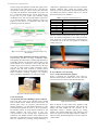
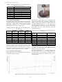
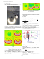
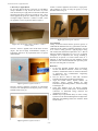
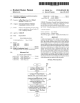
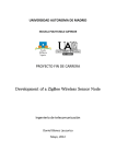
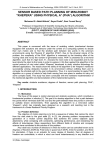
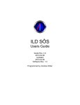
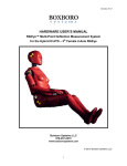
Int ern at ion al Jo u rna l of App lied R es ea rch 2 015 ; 1 (1 0): 25-29
ISSN Print: 2394-7500
ISSN Online: 2394-5869
Impact Factor: 5.2
IJAR 2015; 1(10): 25-29
www.allresearchjournal.com
Received: 19-07-2015
Accepted: 21-08-2015
Er. Pal Riya Bipradas Sanchita
ME Research Student [Power
Devices], Dept. Of ETRX,
PIIT Engineering College,
Mumbai University, India.
Hy510 Grease: Maximum Temperature Support and
Its Application in Cob Led Heat Management
Er. Pal Riya Bipradas Sanchita
Abstract
LEDs (high brightness, high power) applications are increasing exponentially every day. The life span
of an LED depends on the semi-conductor material used as well as the current/heat relationship. The
light output of the LED becomes weaker and weaker and once it reaches 50% of its initial value, the
life expectancy of the LED has, by definition, been reached. A life span of a few hundred and up to
100,000 hours is possible, but only when avoiding high temperatures which drastically reduce the
length of the LED’s life. High temperature not only results in reduction of life span but also causes
surrounding temperature to rise, thus increasing the need for room air conditioning units. Currently
there exist two cooling mechanisms for heavy COB LED structures. One is the use of heat sink of
various designs and other is by using MCPCBs. Cooling of COB LEDs can also be done using simple
cooling solution i.e. use of HY500 series of grease. Use of HY510 grease (which is actually a processor
grease) is sufficient enough to provide good amount of cool mechanism for COB LEDs which has been
proved through this research paper. This paper also proves that the level of heat flow efficiency
increases when heat sink and processor grease HY510 are used together to cool COB LEDs.
Keywords: Thermal conductivity (k), Thermal resistance (RTH), Metal Core Printed Circuit Board
(MCPCB). High Intensity Discharge (HID), Chip-on-board (COB).
Introduction
Conventional light sources have always been able to release heat to the ambient through
infrared radiation, and convection in the case of Fluorescent. This mode of heat transfer
typically does not require advanced cooling methods to facilitate the process. LED sources
however lose heat through conduction, which requires the additional knowledge of how to
carry waste heat out of the LED efficiently in order to prevent system failure. An overview
of the different modes of heat loss for various light sources can be seen in TABLE1.
Table 1: Light Source Heat Loss Mode Comparison
Light Source
Incandescent
Fluorescent
HID
LED
Heat Loss %
(Radiation)
~ 90
~40
~90
~5
Heat Loss %
(Convection)
~5
~ 40
~5
~5
Heat Loss %
(Conduction)
~5
~ 20
~5
> 90
Chip-on-board packaging enables plug and play benefits. In fact, packaging is now a key
factor in the device’s total cost. The most prominent of these packaging types is chip-onboard (COB). With chip on board, several LEDs are mounted directly on the printed circuit
board using wire bonds instead of pin connection type.
Correspondence
Er. Pal Riya Bipradas Sanchita
ME Research Student [Power
Devices], Dept. Of ETRX,
PIIT Engineering College,
Mumbai University, India.
A. Cob Led Cooling Mechanism 1 (Existing Technology)
Below figure1 depicts how a COB LEB cooling setup using copper lid (condenser), copper
pad and MCPCB is utilized. The copper thermal pad of the chip package is directly
soldered to MCPCB to provide low resistance path. Here 2 phase technique is used. “2Phase” in this case means the use of evaporation and condensation in order to dramatically
increase the heat transfer characteristics of the device. Even though it provides efficient
cooling, limitation that exist is that:- for cooling 1 LED which cost around Rs25/-, MCPCB
~ 25 ~ International Journal of Applied Research
structure along with aluminum heat sink and copper pad are
used which not only adds weight to this 1 LED but also
increases the overall cost. Now if I want to glow more than
700 LEDs and MCPCB to hold 20LEBs cost around US
$13 – 18 then think about the cost. And for 1LED setup (as
in fig1) why to go for 2-phase type technique. 2-pase
mechanism do not work well if LED module is placed 300
(i.e. in inclined position). 2 phase technology is only to be
applied to cool devices or components when heat flux
generated goes beyond 350W/m2.
COB LEDs in application areas such as home, restaurants,
hospitals, exhibition areas, schools and colleges, along
streets etc. As per my experiment, the temperature of HY510
rises initially but comes to a constant value of 55 0C after 24
minutes of Operation (see TABLE 2).
Table 2: Temperature Withstand By Hy510
Time (Minutes)
Initial : 4
8
12
16
20
24
28 (final)
Temperature Detail Of Hy510 (Oc)
34
43
48
54
55
55
55
The HY510 starts becoming thin at above 140 0C (see fig 3).
Since, the saturation temperature of 3W COB LED remains
nearly equal to 65 0C, applying HY510 is not limited only up
to processors but can be very well applied for COB LED
cooling of any type.
Fig1: Cross Sectional View of Single COB LED Package Using
MCPCB (FR-4)
B. Cob Led Cooling Mechanism 2 (Existing Technology)
Approximately 16%-20% of energy consumption comes
from lighting; the LED market is pushing high demands on
ecofriendly solutions. For this reason passive means are the
prime methods to be considered to cool COB LEDs and
modules. Figure 2 shows the use of heat sink stack having a
core tube in which 2-phase cooling mechanism (active)
happens. Heat sink stack continues to perform passive
mechanism. However such systems (shown in figure2) have
further drawbacks including, operating cost, reliability
issues, performance degradation over time and its weight.
Fig 3: The HY510 starts becoming thin at above 140 0C
B. Test of Hy510: Cob Led Cooling
Case 1: No Heat Sink and Hy510 Applied
Figure 4 represents the experimental setup where T1
measures the temperature of Heat sink (for case 1 heat sink
was removed) and T2 measures LED board temperature.
Fig 2: LEDTM Module with Heat Exchanger
II. All about Hy510
A. Experiment Done: Heat Handling Capacity of Hy510
There exist many series of HY Thermal Grease. HY500
series includes HY510, HY520, HY530, and HY550. All
HY500 grease series are processor grease.HY510 has
thermal conductivity 1.93 and thermal impedance as 0.225
and operating temperature up to 280 0C as per provided by
HY-company manual. Its actual thermal conductivity and
thermal resistance has been proved in part “IVCALCULATION” in this research paper. Actual thermal
conductivity and thermal resistance value obtained is less
than what it is mentioned in the user manual but even then
HY510 is sufficient for providing cooling mechanism to
Fig 4: Experimental setup
When no HY510 as well as Heat sink is applied to COB
LED, T2 displays very high temperature. This can not only
damage the LED module but also increases the air
temperature around it. Without applying any cooling
solution, max saturated temperature zone reached by LED
board is 63 0C that too for 3W module (shown in TABLE 3).
Then how much saturated temperature it will be reached for
+20W module?
~ 26 ~ International Journal of Applied Research
Table 3: Temperature Reached By Cob Led Module Having
No Applied Cooling Mechanism
Time (min)
10
20
30
40
50
60
70
80
90
100
COB LED Board Temp T2 (oC)
32
46
49
53
58
61
62
63
63
63
Fig 5: Heat Sink + HY510
Case 2: Only Heat Sink Applied
Placing heat sink at the base of the module will raise the heat
conduction mechanism (TABLE 4 proves it). It serves better
than case 1. Using HEAT SINK, COB LED Board
Temperature dropped to 44 oC which marks saturated
temperature for case 2 (check TABLE 3 and 4).
Table 4: Temperature Reached By Cob Led Module (Heat
Sink Applied)
Time (min)
Initial :10
20
30
40
50
60
70
80
90
Final: 100
LED Board
Temp (oC)
32
34
35
38
40
41
44
44
44
44
Heat Sink
Temp (oC)
32
41
45
47
48
49
49
49
49
49
When HY510 is applied, board’s heat is absorbed by both
HY510 and the Heat Sink. Comparing TABLE 4 and
TABLE 5 clearly proves it that there is a good reduction in
the board’s temperature form 63 0C to 40 0C and a rise in
Heat sink’s temperature from 49 oC to 50 oC. Rise in heat
sink’s temperature is seen because the HY510 provides a
good transfer path for the heat generated by the board
towards the heat sink.
Table 5: Temperature Reached By Cob Led Module (Heat Sink +
Hy510 Applied)
Room
Temp(oC)
32
32
32
32
33
33
36
36
36
37
Heat Sink’s temperature rises along with time because of the
fact that it performs cooling mechanism and keeps absorbing
heat from the board. After certain time (here its 50 min),
each and every point on heat sink receives uniform heat
distribution. Thus static temperature of 49 oC is reached.
Case 3: Heat Sink + Hy510 Applied
Thermal Silver Grease HY510 is applied at the interface b/w
COB board and Heat sink (Fig 5).
Time
(min)
10
20
30
40
50
60
70
80
90
100
COB LED Board’s Temp
(oC)
30
33
34
35
37
40
40
40
40
40
Heat Sink’s Temp
(oC)
37
44
47
48
49
49
50
50
50
50
LED Board’s temperature level is maintained at lower level
by HY510. In short, HY510 has increased the heat
conduction ability of the heat sink.
See figure 6.Temperature of COB LED Board at the
beginning reached a level of 63 0C without applying any
cooling mechanism. This temperature is reduced to 44 0C by
only heat sink and further more reduction is seen i.e. 40 0C
by HY510 grease.
Fig 6: Represents the plot of LED Board’s temp (green-case1, red- case 2 & blue- case 3)
~ 27 ~ International Journal of Applied Research
III. Thermal Graph
Figure 7 shows the actual image of 3W COB LED Module
whose thermal imaging test has been performed.
Fig 9: Represents The Thermal Images of LED Module (Heat
_Sink+ HY510 Grease)
IV. Calculations
A. To Measure Thermal Conductivity of Hy510
Separation distance/length (between heat source & heat sink)
= 10mm = 0.01m
Q = 3 Watts
T = 37 0C-300C = 7 0C = 280.150K ....... see from TABLE 5
Radius = 16mm = 0.016 m
Area = πr2 = 3.14x 0.016 x 0.016 m2
Thus Thermal Conductivity “k” of HY510 =
=
.
.
Rth =
Fig 7: Actual Image of 3W COB LED Module
In Figure 8, 1ST represents the 3W LED when power supply
was not turned ON. 2ND represents the image taken at 20min
(TABLE 4), 3RD thermal view was taken at 40min and 4TH
thermal record was captured at 90min.
.
.
=
.
.
.
= 0.133 W/m_K
= 0.07518 m2K/W
A. Effectiveness (ϵ) Provided By Single Aluminium Fin
See TABLE 5 readings.
Assume that the entire fin has received uniform temperature
distribution. i.e. T1= T2 = T3 = 37 0C (see fig 10).
Rth (R) = Thermal resistance from fin to ambient.
Rth (Ct) = Thermal resistance offered from heat source to fin
root + by the aluminum material (see fig10)
Fig 10: Resistance Model
Fig 8: Represents the 4 Thermal behaviour of heat sink in 3W COB
LED
Thermal images 1, 2 and 3 given in figure 9 were taken when
HY510 was applied b/w the LED circuit-on-chip plate and
heat sink. 1ST represents the 3W LED when power supply
was not turned ON. 2ND image was taken at time 20min, 3RD
image at time 40min. HY510 proves very effective in
thermal management. This can be proved by comparing the
images 2 & 3 of figure number 9 (below) with 2 & 3 of
figure number 8 (above).
Air temperature measured was 28 0C and fin temperature as
370C
T = 37 0C -28 0C = 9 0C = 282.150K
Power (Q) = 3W
Cross sectional area (A) of 1 fin = 1mm x 22mm = 0.001m x
0.022m
Thermal conductivity ‘k’of aluminum = 229 W/m_0C
∆
Rth (R) = = = 3 0C/W
Rth (Ct) =
=
Effectiveness (ϵ) =
.
.
.
=
= 3.96 0C/W
.
= 1.32
Cooling Effectiveness provided by complete heat sink = (30
fins x 1.32) = 39.6%
~ 28 ~ International Journal of Applied Research
V. Best Way to Apply Hy510
Do not apply HY510 directly to the base of COB Board.
Always remember to wipe out the dirt with a dry cotton
cloth. Second step is to apply HY510 to the base of the board
where the heat sink is going to be screwed up. Now, I have
tested (applied) this grease in 3 different styles. A glass slab
of length x height x thickness = 126mm x 61.5mm x 5mm
was applied as a source of pressure shown in figure 11.
STYLE 3: Grease is applied in uneven form i.e. zigzag form.
This technique too does not help the grease to evenly
distribute itself (see fig 14).
Fig14: Application of grease ‘STYLE 3’
Fig 11: Glass slab of length x height x thickness = 126mm x
61.5mm x 5mm
STYLE 1: Grease is applied in the circular form/ dot form
(Fig12). This style is highly recommended in majority of
applications and also in my experimental test as it spreads
itself uniformly.
Fig12: Application of grease ‘STYLE 1’
STYLE 2: Grease is applied in vertical line or in horizontal
line form. This technique does not help the grease to evenly
distribute itself (see fig 13).
VI. Conclusion
Testing of HY510 Thermal Grease (processor grease) on
COB LED 3W Module showed very good effective outcome.
COB LED of 3W reached a saturation temperature zone of
65 0C with no cooling provision. Applying HY510 along
with Al Heat sink reduced the temperature to 40 0C. Rule of
thumb in thermal management says “For every 10 degrees
Centigrade rise in temperature, the average reliability is
decreased by 50 percent.” So in this research work, 25 0C
reduction is achieved. Hence life span reliability remains
unaffected on 3W COB LED Module when processor grease
HY510 is used along with ‘Al’ heat sink.
References
1. Er Pal Riya, Bipradas Sanchita. Heat in Electronic
Circuits and Material Selection Criteria for Cooling
Solutions, International Journal of Advanced Research
in Electronics and Communication Engineering
(IJARECE). 2015; (4):3.
2. Seri Lee. How To Select A Heat Sink, Advanced
Thermal EngineeringAavid Thermal Technologies.
3. Angie Fan, Richar Bonner, Stephen Sharratt. An
Innovative Passive Cooling Method for High
Performance Light Emitting Diodes”, Advanced Cooling
Technologies. Inc.
4. Yusuf Yasa, Ramazan Ayaz, Ali Durusu. Thermal
Management of Power LED System, 3rd International
Conference on Renewable Energy Research and
Applications, Oct 2014.
5. Mehmet Kaya. Experimental Study on Active Cooling
Systems Used for Thermal Management of High-Power
Multichip Light-Emitting Diodes, the Scientific World
Journal. 2014, 7.
Fig13: Application of grease ‘STYLE 2’
~ 29 ~