1
International Journal of Applied Research
structure along with aluminum heat sink and copper pad are
used which not only adds weight to this 1 LED but also
increases the overall cost. Now if I want to glow more than
700 LEDs and MCPCB to hold 20LEBs cost around US
$13 – 18 then think about the cost. And for 1LED setup (as
in fig1) why to go for 2-phase type technique. 2-pase
mechanism do not work well if LED module is placed 300
(i.e. in inclined position). 2 phase technology is only to be
applied to cool devices or components when heat flux
generated goes beyond 350W/m2.
COB LEDs in application areas such as home, restaurants,
hospitals, exhibition areas, schools and colleges, along
streets etc. As per my experiment, the temperature of HY510
rises initially but comes to a constant value of 55 0C after 24
minutes of Operation (see TABLE 2).
Table 2: Temperature Withstand By Hy510
Time (Minutes)
Initial : 4
8
12
16
20
24
28 (final)
Temperature Detail Of Hy510 (Oc)
34
43
48
54
55
55
55
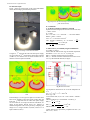
The HY510 starts becoming thin at above 140 0C (see fig 3).
Since, the saturation temperature of 3W COB LED remains
nearly equal to 65 0C, applying HY510 is not limited only up
to processors but can be very well applied for COB LED
cooling of any type.
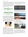
Fig1: Cross Sectional View of Single COB LED Package Using
MCPCB (FR-4)
B. Cob Led Cooling Mechanism 2 (Existing Technology)
Approximately 16%-20% of energy consumption comes
from lighting; the LED market is pushing high demands on
ecofriendly solutions. For this reason passive means are the
prime methods to be considered to cool COB LEDs and
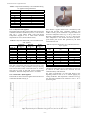
modules. Figure 2 shows the use of heat sink stack having a
core tube in which 2-phase cooling mechanism (active)
happens. Heat sink stack continues to perform passive
mechanism. However such systems (shown in figure2) have
further drawbacks including, operating cost, reliability
issues, performance degradation over time and its weight.
Fig 3: The HY510 starts becoming thin at above 140 0C
B. Test of Hy510: Cob Led Cooling
Case 1: No Heat Sink and Hy510 Applied
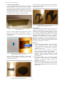
Figure 4 represents the experimental setup where T1
measures the temperature of Heat sink (for case 1 heat sink
was removed) and T2 measures LED board temperature.
Fig 2: LEDTM Module with Heat Exchanger
II. All about Hy510
A. Experiment Done: Heat Handling Capacity of Hy510
There exist many series of HY Thermal Grease. HY500
series includes HY510, HY520, HY530, and HY550. All
HY500 grease series are processor grease.HY510 has
thermal conductivity 1.93 and thermal impedance as 0.225
and operating temperature up to 280 0C as per provided by
HY-company manual. Its actual thermal conductivity and
thermal resistance has been proved in part “IVCALCULATION” in this research paper. Actual thermal
conductivity and thermal resistance value obtained is less
than what it is mentioned in the user manual but even then
HY510 is sufficient for providing cooling mechanism to
Fig 4: Experimental setup
When no HY510 as well as Heat sink is applied to COB
LED, T2 displays very high temperature. This can not only
damage the LED module but also increases the air
temperature around it. Without applying any cooling
solution, max saturated temperature zone reached by LED
board is 63 0C that too for 3W module (shown in TABLE 3).
Then how much saturated temperature it will be reached for
+20W module?
~ 26 ~