1
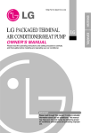
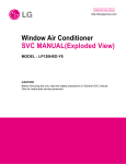
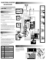
PACKAGED TERMINAL AIR CONDITIONER
/HEAT PUMP TECH SHEET
Schematic Diagram
NEUTRAL
LIVE
WH
BK
In part "A", there are 3 types.
Disconnect from Electrical Supply
Before Servicing Unit
GN/YL
TB3
Electrical Requirements
1. Do not use an extension cord with this unit.
2. When the unit is in the OFF position, the power supply to the electrical controls is
still energized.
3. Disconnect the power to the unit before servicing the unit.
4. Remove the power cord from the wall receptacle.
5. Remove or turn off the protective device (fuses or circuit breaker).
BK1
RD
BK2
BL
BK3
RD
BK4
BL
TB4
BK
OR
TB1
WH
TB2
WH
Type.1
BK
OR
OUTDOOR
FAN
MOTOR
WH
BK
OUTDOOR
FAN
MOTOR
INDOOR COIL
THERMISTOR
INDOOR AIR
THERMISTOR
BK
OR(BR)
YL
BK
BL
RD
OR(BR)
YL
BL
OR(BR)
YL
Type.3
FUSE- Use a time-delay fuse or circuit breaker. Refer to the nameplate for proper
power supply requirements.
OUTDOOR
FAN
MOTOR
"A"
BK
OR(BR)
YL
F
INDOOR AIR
THERMISTOR
BK
BL
RD
OR(BR)
YL
INDOOR COIL
THERMISTOR
OUTDOOR
FAN
MOTOR
BK
RD
BL
COMP
BK
BL
RD
OR(BR)
YL
RD
OR(BR)
YL
In part "B", there are 2 types.
Type.1
HERM
R
Self-Diagnosis
BK
Type.2
Wirings including installation of the receptacle must comply with the NEC and local
codes, local regulations.
208, 230, and 208/230 VOLT UNITS
These units are equipped with a three-prong grounding plug on the power supply
cord which must be plugged into a matching properly grounded three-prong wall
receptacle for your protection against possible shock hazard. If such an outlet is not
present, one must be installed by a qualified electrician in accordance with the
National Electrical Code and local codes and ordinances.
NOTE: DO NOT USE AN EXTENSION CORD on 208, 230, and 208/230 Volt units.
BK
BL
RD
OR(BR)
YL
INDOOR
FAN
MOTOR
BK
RD
BL
BK
BL
RD
OR
BR
YL
BL
RD
OR
BR
YL
GN/YL
OLP
FUNCTION:
If the unit has a malfunction, a green OPERATION LED located on the Display PCB
used by the unit to indicate the errors.
USE:
If the customer has to register a complaint to the service center, he can be very
clear about registering the complaint that what is happening & by referring the
user's manual the customer can clearly define the problem.
So that the engineer should go fully prepared with the prescribled tools to be used
regarding that problem. It also keeps the customer aware about the unit.
Here are some of the problems defined below for which the LED indicates by
flashing number of times the error has been reconrded against it.
The errors are the mentioned which is as follows:
ON
OFF
Fault Codes
CH 01
CH 02
CH 03
CH 04
CH 05
CH 06
CH 07
Normal
No power / failed board
Indoor Air Thermistor Error
Indoor Coil Thermistor Error
Outdoor Air Thermistor Error (PIHP Only)
Outdoor Coil Thermistor Error (PIHP Only)
Mode Error
Setpoint Error
Bad Thermistor Wiring
"B"
INDOOR
FAN
MOTOR
BK
BL
RD
OR
BR
YL
BL
RD
OR
BR
YL
GN/YL
Type.2
INDOOR
FAN
MOTOR
FAN
CAPACITOR
GN/YL
Additional Controls
The additional controls are located behind the
option cover of control box. The standard settings
will be in the OFF position. The authorized servicer
has to check switches and ensure the switches are
in the desired position.
REMOTE ON
ON
ON
ON
ON
ON
OFF
5
OFF
6
OFF
7
ON
OFF
LOCAL OFF OFF OFF
1
2
3
4
Remote/Local
Energy Saver
Temperature Limit 1
Temperature Limit 2
Temperature Limit 3
PTAC/PTHP
UNIT TYPE
BK
BL
RD
OR
BR
YL
BK
RD
OR
BR
YL
Temperature Limiting
Temperature Limiting can save money by limiting the lowest temperature for cooling
and the highest temperature for heating. The temperature limiting is controlled by
switches #1 - #3.
This temperature limiting is not available with the Remote Wall Thermostat.
Temperature
Limit #1
Temperature
Limit #2
Temperature
Limit #3
OFF
OFF
ON
OFF
Cooling Operation
Heating Operation
OFF
Lowest Temp.
54° F (12.2° C)
Highest Temp.
86° F (30.0° C)
Lowest Temp.
54° F (12.2° C)
Highest Temp.
86° F (30.0° C)
OFF
56° F (13.3° C)
86° F (30.0° C)
54° F (12.2° C)
84° F (28.9° C)
OFF
ON
OFF
58° F (14.4° C)
86° F (30.0° C)
54° F (12.2° C)
82° F (27.8° C)
ON
ON
OFF
60° F (15.5° C)
86° F (30.0° C)
54° F (12.2° C)
80° F (26.7° C)
OFF
OFF
ON
62° F (16.6° C)
86° F (30.0° C)
54° F (12.2° C)
78° F (25.5° C)
ON
OFF
ON
64° F (17.7° C)
86° F (30.0° C)
54° F (12.2° C)
76° F (24.4° C)
— Replacement of the refrigeration cycle.
1. When replacing the refrigeration cycle, be sure to discharge the refrigerant system using a
refrigerant recovery system.
If there is no valve to attach the recovery system, install one (such as a WATCO A-1) before
venting the refrigerant. Leave the valve in place after servicing the system.
2. After discharging the unit completely, remove the desired component, and unbraze the
pinch-off tubes.
3. Solder service valves into the pinch-off tube ports, leaving the valves open.
4. Solder the pinch-off tubes with service valves.
5. Evacuate as follows.
1) Connect the vacuum pump, as illustrated Figure 1.
2) Start the vacuum pump, slowly open manifold valves A and B with two full turns
counterclockwise and leave the valves closed. The vacuum pump is now pulling through
valves A and B up to valve C by means of the manifold and entire system.
COMPLAINT
Fan motor will not run.
ON
ON
66° F (18.9° C)
86° F (30.0° C)
54° F (12.2° C)
74° F (23.3° C)
ON
ON
ON
68° F (20.0° C)
86° F (30.0° C)
54° F (12.2° C)
72° F (22.2° C)
#6
OFF
OFF
#7
OFF
ON
Unit Type
Cooling+Electric Heater+Heat Pump
Cooling+Electric Heater
OR
ON
ON
OFF
ON
Heat Pump Only
Cooling Only
Troubleshooting Guide
In general, possible trouble is classified in two causes.
The one is Starting Failure which is caused from an electrical defect, and the other is
Ineffective Air Conditioning caused by a defect in the refrigeration circuit and
improper application.
Unit is running but cooling is ineffective
Ineffective Cooling
Check of cold air circulation
for smooth flow.
Dirty indoor coil
(Heat exchanger)
Check of outdoor coil
(heat exchanger) & the fan
operation.
Check heat load increase.
Unexpected residue
Check gas leakage.
Overloaded Circuit
Malfunction of fan
Repair gas leak.
Clogged of air filter
Obstruction at air outlet
Replacement of unit if the
unit is beyond repair.
Adjusting of refrigerant
charge
Correct above trouble
Check clogging in
refrigeration circuit.
Repair clogging in
refrigeration circuit.
Check of inside gas
pressure.
Malfunction of compressor
Satisfactory operation with
temperature difference of
inlet & outlet air 44.6~50˚ F
(7~10˚ C)
Replacement of
compressor
Fails to Start
Check power source.
Check circuit breaker and fuse.
Gas leakage of feeler bulb
of thermostat
Check control switch
setting.
T/P
C
3) Operate the vacuum pump for 20 to 30 minutes, until 600 microns of vacuum are
obtained. Close valves A and B, and observe the vacuum gauge for a few minutes.
A rise in pressure would indicate a possible leak or moisture remaining in the system.
With valves A and B closed, stop the vacuum pump.
4) Remove the hose from the vacuum pump and place it on the charging cylinder.
See Figure 2. Open valve C.
Discharge the line at the manifold connection.
5) The system is now ready for final charging.
6. Recharge as follows :
1) Refrigeration cycle systems are charged from the high-side. If the total charge cannot be
put in the high-side, the balance will be put in the suction line through the access valve
which you installed as the system was opened.
2) Connect the charging cylinder as shown in Figure 2. With valve C open, discharge the
hose at the manifold connection.
3) Open valve A and allow the proper charge to enter the system. Valve B is still closed.
4) If more charge is required, the high-side will not take it. Close valve A.
5) With the unit running, open valve B and add the balance of the charge.
a. Do not add the liquid refrigerant to the low-side.
b. Watch the low-side gauge; allow pressure to rise to 30 lbs.
c. Turn off valve B and allow pressure to drop.
d. Repeat steps B and C until the balance of the charge is in the system.
6) When satisfied the unit is operating correctly, use the pinch-off tool with the unit still
running and clamp on to the pinch-off tube. Using a tube cutter, cut the pinch-off tube
about 2 inches from the pinch-off tool. Use sil-fos solder and solder pinch-off tube
closed. Turn off the unit, allow it to set for a while, and then test the leakage of the
pinch-off connection.
SUB
CON2 CON1
Improper thermostat setting
Defect of compressor
capacitor.
CONDENSER
(HIGH PRESSURE SIDE)
OBM-2504U1
Main : 340
C1 : 52.8
OBM-2202U1
Main : 813
C1 : 52
C2 : 39.6
SUB : 208
C2 : 52
SUB : 264
Replacement of fan motor
Regular but fails to start
Irregular motor insulation ( )
Replacement of compressor
(locking of rotor, metal)
Replacement of compressor
(Motor damaged)
Wire disconnected or
connection loose
Connect wire. Refer to wiring diagram for terminal
identification. Repair or replace loose terminal.
Capacitor (Discharge
capacitor before testing.)
Test capacitor.
Replace if not within ±10% of manufacturer's
rating. Replace if shorted, open, or damaged.
OR
Will not rotate
Fan blade hitting shroud or cross flow fan hitting
scroll. Realign assembly.
S1(C1) S2(C2)
YL
Units using slinger ring condenser fans must
have 1/4 to 5/16 inch clearance to the base. If it is
hitting the base, shim up the bottom of the fan
motor with mounting screw(s).
RD(LOW)
BL(MED)
BK(HI)
Resistance of coil (at 75°C, Ω)
OBM-3018U1
Main : 165
C1 : 48.2
C2 : 48.2
SUB : 63.0
Check fan motor bearings; if motor shaft will not
rotate, replace the motor.
Revolves on overload.
Fan motor runs
intermittently
MANIFOLD
GAUGE
Pay attention to any change from high speed to
low speed. If the speed does not change, replace
the motor.
Fan motor noise.
Grommets
Check grommets; if worn or missing, replace them.
Fan
If cracked, out of balance, or partially missing,
replace it.
Turbo fan
If cracked, out of balance, or partially missing,
replace it.
Loose set screw
Tighten it.
Worn bearings
If knocking sounds continue when running or
loose, replace the motor. If the motor hums or
noise appears to be internal while running,
replace motor.
COMPLAINT
Compressor will not run,
but fan motor runs.
CAUSE
Check voltage. See the limits on the preceding.
page. If not within limits, call an electrician.
Wiring
Check the wire connections, if loose, repair or
replace the terminal. If wires are off, refer to wiring
diagram for identification, and replace. Check wire
locations. If not per wiring diagram, correct.
Rotary
Check for continuity, refer to the wiring diagram
for terminal identification. Replace the switch if
circuit is open.
Thermostat
Check the position of knob If not at the coldest
setting, advance the knob to this setting and
restart unit.
Check continuity of the thermostat. Replace
thermostat if circuit is open.
Capacitor (Discharge
capacitor before
servicing.)
Check the capacitor.
Replace if not within ±10% of manufacturers
rating. Replace if shorted, open, or damaged.
Compressor
Check the compressor for open circuit or
ground. If open or grounded, replace the
compressor.
EXTERNAL
VACUUM PUMP
A
EVAPORATOR
(LOW PRESSURE SIDE)
Figure 1-Pulling Vacuum
LOW
HI
Overload
COMPRESSOR
B
REMEDY
Voltage
B
B
Check voltage. See limits on this page. If not within
limits, call an electrician.
Test capacitor.
Check bearings. Does the fan blade rotate freely?
If not, replace fan motor.
A
A
CHARGING
CYLINDER
C
Irregular motor resistance ( )
Check switch continuity. Refer to wiring diagram
for terminal identification. Replace switch if
defective.
< Outdoor motor >
COMPOUND GAUGE
SEE INSETS
BELOW
Defect of fan motor capacitor.
Improper wiring
Replacement.
Rotary switch
RD(LO)
Resistance of coil (at 75°C, Ω)
CAPILLARY TUBE
Improper wiring.
Irregular motor resistance ( ).
Irregular motor insulation ( ).
Check voltage to rotary switch. If none, check
power supply cord. Replace cord if circuit is open.
BL(MID)
Loose terminal connection.
Check capacitor.
Power supply cord
BK(HI)
YL
Equipment needed: Vacuum pump, charging cylinder, manifold gauge, brazing equipment.
pinch-off tool capable of making a vapor-proof seal, leak detector, tubing cutter, hand tools to
remove components, service valve.
Only fan fails to start.
Drop of power voltage.
Check voltage at outlet. Correct if none.
POWER
M
SUB
Check control switch.
Only compressor fails to
start.
No power
MAIN
If high vacuum equipment is used, just crack valves A and B for a few minutes, then
open slowly with the two full turns counterclockwise. This will keep oil from foaming and
being drawn into the vacuum pump.
REMEDY
< Indoor motor >
BR
CAP.
OFF
CAUSE
Check the compressor overload, if externally
mounted. Replace if open. (If the compressor
temperature is high, remove the overload, cool it,
and retest.)
ROOM AIR CONDITIONER VOLTAGE LIMITS
NAME PLATE RATING
MINIMUM
MAXIMUM
208/230V
187V
252V
Figure 2-Charging
P/No.: 3850A20594H