1
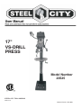
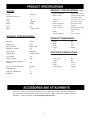
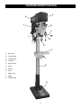
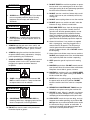
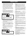
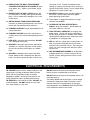
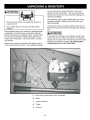
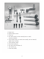
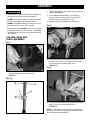
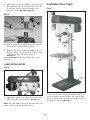
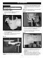
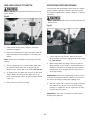
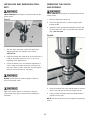
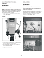
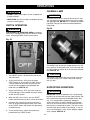
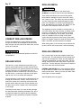
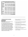
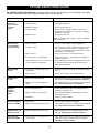
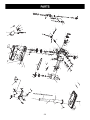
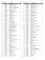
R
17"
VS-DRILL
PRESS
Model Number
20525
STEEL CITY TOOL WORKS
VER. 03.09
Manual Part No. OR74656
R
2
TABLE OF CONTENTS
INTRODUCTION
SECTION 1
Warranty .................................................................................................................................................4
SECTION 2
Product Specifications ............................................................................................................................7
SECTION 3
Accessories and Attachments ................................................................................................................7
SECTION 4
Definition of Terms ..................................................................................................................................8
SECTION 5
Feature Identification ..............................................................................................................................9
SECTION 6
General Safety......................................................................................................................................10
SECTION 7
Product Safety ......................................................................................................................................13
SECTION 8
Electrical Requirements........................................................................................................................14
SECTION 9
Unpacking & Inventory..........................................................................................................................16
SECTION 10
Assembly ..............................................................................................................................................18
SECTION 11
Adjustments ..........................................................................................................................................21
SECTION 12
Operations ............................................................................................................................................25
SECTION 13
Maintenance .........................................................................................................................................28
SECTION 14
Troubleshooting ....................................................................................................................................29
SECTION 15
Parts List...............................................................................................................................................30
INTRODUCTION
This user manual is intended for use by anyone working with this machine. It should be kept available
for immediate reference so that all operations can be performed with maximum efficiency and safety.
Do not attempt to perform maintenance or operate this machine until you have read and understand the
information contained in this manual.
The drawings, illustrations, photographs, and specifications in this user manual represent your machine
at time of print. However, changes may be made to your machine or this manual at any time with no
obligation to Steel City Tool Works.
3
WARRANTY
STEEL CITY TOOL WORKS
5 YEAR LIMITED WARRANTY
Steel City Tool Works, LLC (“SCTW”) warrants all “STEEL CITY TOOL WORKS” machinery to
be free of defects in workmanship and materials for a period of 5 years from the date of the original
retail purchase by the original owner. (Granite components are warranted for 10 years. Please inform
SCTW within 30 days for any damages or defects on the Granite components found upon receipt of
the products to qualify for the 10 year limited warranty. See the Granite warranty statement supplied
with those products.) SCTW will repair or replace, at its expense and at its option, any SCTW
machine, machine part, or machine accessory which in normal use has proven to be defective,
provided that the customer returns the product, shipping prepaid, to an authorized service center with
proof of purchase and provides SCTW with a reasonable opportunity to verify the alleged defect by
inspection. Date code, which can be found on the original carton and machine body, must be
provided to SCTW at the time of any warranty request made. This warranty does not apply to defects
due directly or indirectly to misuse, abuse, negligence, accidents, or lack of maintenance, or to
unauthorized repairs or alterations made or specifically authorized by anyone other than SCTW.
Normal wear components are also excluded under this coverage. Every effort has been made to
ensure that all SCTW machinery meets the highest quality and durability standards. We reserve the
right to change specifications at any time due to our commitment to continuous improvement of the
quality of our products.
EXCEPT AS SET FORTH ABOVE, SCTW MAKES NO EXPRESS OR IMPLIED REPRESENTATIONS
OR WARRANTIES WITH RESPECT TO ITS MACHINERY, OR ITS CONDITION, MERCHANTABILITY, OR FITNESS FOR ANY PARTICULAR PURPOSE OR USE. SCTW FURNISHES THE
ABOVE WARRANTIES IN LIEU OF ALL OTHER WARRANTIES , EXPRESS OR IMPLIED,
INCLUDING THE WARRANTIES OF MERCHANTABILITY AND FITNESS FOR A PARTICULAR
PURPOSE, WHICH ARE HEREBY SPECIFICALLY DISCLAIMED.
SCTW SHALL NOT BE LIABLE FOR ANY (A) SPECIAL, INDIRECT, INCIDENTAL, PUNITIVE OR
CONSEQUENTIAL DAMAGES, INCLUDING WITHOUT LIMITATION LOSS OF PROFITS, ARISING
FROM OR RELATED TO THIS WARRANTY, THE BREACH OF ANY AGREEMENT OR WARRANTY,
OR THE OPERATION OR USE OF ITS MACHINERY , INCLUDING WITHOUT LIMITATION
DAMAGES ARISING FROM DAMAGE TO FIXTURES , TOOLS , EQUIPMENT , PARTS OR
MATERIALS, DIRECT OR INDIRECT LOSS CAUSED BY ANY OTHER PARTY, LOSS OF REVENUE
OR PROFITS, FINANCING OR INTEREST CHARGES , AND CLAIMS BY ANY THIRD PERSON,
WHETHER OR NOT NOTICE OF SUCH POSSIBLE DAMAGES HAS BEEN GIVEN TO SCTW ;
(B) DAMAGES OF ANY KIND FOR ANY DELAY BY OR FAILURE OF SCTW TO PERFORM ITS
OBLIGATIONS UNDER THIS AGREEMENT ; OR (C) CLAIMS MADE A SUBJECT OF A LEGAL
PROCEEDING AGAINST SCTW MORE THAN ONE (1) YEAR AFTER SUCH CAUSE OF ACTION
FIRST AROSE.
The validity, construction and performance of this Warranty and any sale of machinery by SCTW
shall be governed by the laws of the Commonwealth of Pennsylvania, without regard to conflicts of
laws provisions of any jurisdiction. Any action related in any way to any alleged or actual offer,
acceptance or sale by SCTW, or any claim related to the performance of any agreement including
without limitation this Warranty, shall take place in the federal or state courts in Allegheny County,
Pennsylvania.
Tech Service
1-877-724-8665
STEEL CITY TOOL WORKS
Please have your Model No.
and Serial No. available
4
WARRANTY CARD
Name ________________________________________________
Street _______________________________________________
Apt. No. ______________________________________________
City _________________________ State ______ Zip __________
Phone Number_________________________________________
E-Mail ________________________________________________
The following information is given on a voluntary basis
and is strictly confidential.
Where did you purchase your STEEL CITY machine?
Store: ____________________________________________
City:______________________________________________
2.
How did you first learn of Steel City Tool Works?
___ Advertisement
___ Mail Order Catalog
___ Web Site
___ Friend
___ Local Store
Other_______________________
! CUT HERE
3.
4.
5.
6.
7.
Which of the following magazines
___ American Woodworker
––– Cabinetmaker
___ Fine Homebuilding
___ Journal of Light Construction
___ Popular Mechanics
___ Popular Woodworking
___ WOOD
___ WOODEN Boat
___ Woodsmith
___ Woodworker
___ Workbench
What is your age group?
___ 20 to 29 years
___ 40 to 49 years
___ 60 to 69 years
9.
How many Steel City machines do you own? _____________
11. Which benchtop tools do you own? Check all that apply.
___ Belt Sander
___ Belt / Disc Sander
___ Drill Press
___ Band Saw
___ Grinder
___ Mini Jointer
___ Mini Lathe
___ Scroll Saw
___ Spindle / Belt Sander
Other______________________
do you subscribe to?
___ American How-To
___ Family Handyman
___ Fine Woodworking
___ Old House Journal
___ Popular Science
___ Today’s Homeowner
___ Woodcraft
___ Woodshop News
___ Woodwork
___ Woodworker’s Journal
Other_________________
12. Which portable / hand held power tools do you own?
Check all that apply.
___ Belt Sander
___ Biscuit Jointer
___ Dust Collector
___ Circular Saw
___ Detail Sander
___ Drill / Driver
___ Miter Saw
___ Orbital Sander
___ Palm Sander
___ Portable Thickness Planer
___ Saber Saw
___ Reciprocating Saw
___ Router
Other_______________________
13. What machines / accessories would you like to see added to the
STEEL CITY line?
____________________________________________________
____________________________________________________
Which of the following woodworking / remodeling shows do
you watch?
___ Backyard America ___ The American Woodworker
___ Home Time
___ The New Yankee Workshop
___ This Old House
___ Woodwright’s Shop
Other__________________________________________
What is your annual household
___ $20,000 to $29,999
___ $40,000 to $49,999
___ $60,000 to $69,999
___ $80,000 to $89,999
How would you rank your woodworking skills?
___ Simple
___ Intermediate
___ Advance
___ Master Craftsman
10. What stationary woodworking tools do you own?
Check all that apply.
___ Air Compressor
___ Band Saw
___ Drill Press
___ Drum Sander
___ Dust Collection
___ Horizontal Boring Machine
___ Jointer
___ Lathe
___ Mortiser
___ Panel Saw
___ Planer
___ Power Feeder
___ Radial Arm Saw
___ Shaper
___ Spindle Sander
___ Table Saw
___ Vacuum Veneer Press
___ Wide Belt Sander
Other____________________________________________
Product Description:_____________________________________
Model No.: ___________________________________________
Serial No. _____________________________________________
1.
8.
14. What new accessories would you like to see added?
____________________________________________________
____________________________________________________
income?
___ $30,000 to $39,999
___ $50,000 to $59,999
___ 70,000 to $79,999
___ $90,000 +
15. Do you think your purchase represents good value?
___Yes
___ No
16. Would you recommend STEEL CITY products to a friend?
___ Yes
___ No
___ 30 to 39 years
___ 50 to 59 years
___ 70 + years
17. Comments:
____________________________________________________
____________________________________________________
____________________________________________________
____________________________________________________
____________________________________________________
How long have you been a woodworker?
___ 0 to 2 years
___ 2 to 8 years
___ 8 to 20 years
___ over 20 years
5
FOLD ON DOTTED LINE
PLACE
STAMP
HERE
Steel City Tool Works
3656 Enterprise Avenue
Hayward, CA 94545
FOLD ON DOTTED LINE
6
PRODUCT SPECIFICATIONS (cont)
MOTOR
Type
Induction
Continuous duty HP
1
Amps
12/6
Volts
120/240
Phase
Single
Hertz
60
RPM
1725(no load)
Handle Operation
Motor control
Table size
Table tilt
Table movement
Table material
Depth stop type
Depth
Column diameter
360 degree rotation
Industrial push button
with OFF paddle
14" wide x 14" deep
45° left and right
Rack and pinion
Cast iron
External Micro-Adjust
with Quick Set
Yes
3-1/8" (80mm)
PRODUCT SPECIFICATIONS
PRODUCT DIMENSIONS:
Belt type
Poly-V
Pulley type
Step
Belt Tensioning
Motor slide
Number of speeds
VS
Drill speeds
500-2500
Spindle taper
#2Morse taper
Chuck taper
JT3
Chuck capacity
5/8"
Chuck to table dimension
maximum
24"
Chuck to base dimension
43-3/4"
Quill diameter
2"
Quill travel Maximum
Quill lock
6"
Height
Width
Depth
Height
69"
14"
27"
227lbs
SHIPPING DIMENSIONS:
Carton Type
Length
Depth
Height
Gross Weight
Box
58"
26-1/4"
11-1/2"
251lbs
Yes
There are a variety of accessories available for your Steel City Product. For more information on
any accessories associated with this and other machines, please contact your nearest Steel City
distributor, or visit our website at: www.steelcitytoolworks.com.
7
DEFINITION OF TERMS
Belt cover - Can be opened to provide access to belts,
pulleys, and speed chart.
Table - Holds work piece.
Column - Used to support work table and drill press
head.
On/Off switch - Access power to drill press or turn
power off.
Base - Sits on floor, adds stability, and attaches to
column.
Feed handles - Used to lower chuck and apply
pressure toward work piece.
Depth scale - Keeps track of tool travel into work
piece.
Quill lock - Holds quill in predetermined position.
Keyed chuck - Key is used to loosen or tighten drilling
and sanding tools.
Motor - Supplies power to drill press.
Flexible lamp - Provides light source for all operations.
8
FEATURE IDENTIFICATION
A
K
J
B
C
I
D
E
F
A.
Belt cover
B.
On/Off switch
C.
Feed handles
D.
Quill lock
E.
Keyed chuck
F.
Table
G.
Column
H.
Base
I.
Depth scale
J.
Motor
K.
Flexible lamp
G
H
9
GENERAL SAFETY
!
!
WARNING
WARNING
TO AVOID serious injury and damage to the machine,
read and follow all Safety and Operating Instructions
before assembling and operating this machine.
This manual is not totally comprehensive. It does not
and can not convey every possible safety and operational problem which may arise while using this
machine. The manual will cover many of the basic and
specific safety procedures needed in an industrial environment.
Exposure to the dust created by power sanding, sawing, grinding, drilling and other construction activities
may cause serious and permanent respiratory or
other injury, including silicosis (a serious lung disease), cancer, and death. Avoid breathing the dust,
and avoid prolonged contact with dust. The dust
may contain chemicals known to the State of
California to cause cancer, birth defects or other
reproductive harm.
All federal and state laws and any regulations having
jurisdiction covering the safety requirements for use of
this machine take precedence over the statements in
this manual. Users of this machine must adhere to all
such regulations.
Some examples of these chemicals are:
• Lead from lead-based paints.
• Crystalline silica from bricks, cement and other
masonry products.
• Arsenic and chromium from chemically-treated
lumber.
Below is a list of symbols that are used to attract your
attention to possible dangerous conditions.
!
This is the international safety alert symbol. It is used
to alert you to potential personal injury hazards. Obey
all safety messages that follow this symbol to avoid
possible injury or death.
!
Always operate tool in well ventilated area and provide for proper dust removal. Use a dust collection
system along with an air filtration system whenever
possible. Always use properly fitting NIOSH/OSHA
approved respiratory protection appropriate for the
dust exposure, and wash exposed areas with soap
and water.
DANGER
Indicates an imminently hazardous situation which, if
not avoided, WILL result in death or serious injury.
!
1. To avoid serious injury and damage to the machine,
read the entire User Manual before assembly and
operation of this machine.
WARNING
Indicates a potentially hazardous situation which, if not
avoided, COULD result in death or serious injury.
!
CAUTION
!
WARNING
Indicates a potentially hazardous situation, if not avoided, MAY result in minor or moderate injury. It may also
be used to alert against unsafe practices.
CAUTION
2. ALWAYS wear eye protection. Any machine can
throw debris into the eyes during operations,
which could cause severe and permanent eye
damage. Everyday eyeglasses are NOT safety
glasses. ALWAYS wear Safety Goggles (that
comply with ANSI standard Z87.1) when operating power tools.
CAUTION used without the safety alert symbol indicates a potentially hazardous situation which, if not
avoided, may result in property damage.
NOTICE
This symbol is used to alert the user to useful information about proper operation of the machine.
10
!
11. DO NOT FORCE the machine to perform an operation for which it was not designed. It will do a safer
and higher quality job by only performing operations
for which the machine was intended.
WARNING
12. DO NOT stand on a machine. Serious injury could
result if it tips over or you accidentally contact any
moving part.
3. ALWAYS wear hearing protection. Plain cotton is
not an acceptable protective device. Hearing
equipment should comply with ANSI S3.19
Standards.
!
13. DO NOT store anything above or near the machine.
14. DO NOT operate any machine or tool if under the
influence of drugs, alcohol, or medication.
WARNING
15. EACH AND EVERY time, check for damaged parts
prior to using any machine. Carefully check all
guards to see that they operate properly, are not
damaged, and perform their intended functions.
Check for alignment, binding or breakage of all
moving parts. Any guard or other part that is damaged should be immediately repaired or replaced.
4. ALWAYS wear a NIOSH/OSHA approved dust
mask to prevent inhaling dangerous dust or airborne particles.
16. Ground all machines. If any machine is supplied
with a 3-prong plug, it must be plugged into a 3contact electrical receptacle. The third prong is
used to ground the tool and provide protection
against accidental electric shock. DO NOT remove
the third prong.
5. ALWAYS keep the work area clean, well lit, and
organized. DO NOT work in an area that has slippery floor surfaces from debris, grease, and wax.
6. ALWAYS unplug the machine from the electrical
receptacle before making adjustments, changing
parts or performing any maintenance.
17. Keep visitors and children away from any machine.
DO NOT permit people to be in the immediate work
area, especially when the machine is operating.
7. AVOID ACCIDENTAL STARTING. Make sure that
the power switch is in the “OFF” position before
plugging in the power cord to the electrical
receptacle.
!
18. KEEP protective guards in place and in working
order.
19. MAINTAIN your balance. DO NOT extend yourself
over the tool. Wear oil resistant rubber soled shoes.
Keep floor clear of debris, grease, and wax.
WARNING
20. MAINTAIN all machines with care. ALWAYS KEEP
machine clean and in good working order. KEEP all
blades and tool bits sharp.
8. AVOID a dangerous working environment. DO
NOT use electrical tools in a damp environment
or expose them to rain or moisture.
!
21. NEVER leave a machine running, unattended. Turn
the power switch to the OFF position. DO NOT
leave the machine until it has come to a complete
stop.
22. REMOVE ALL MAINTENANCE TOOLS from the
immediate area prior to turning the machine ON.
WARNING
23. SECURE all work. When it is possible, use clamps
or jigs to secure the workpiece. This is safer than
attempting to hold the workpiece with your hands.
9. CHILDPROOF THE WORKSHOP AREA by
removing switch keys, unplugging tools from the
electrical receptacles, and using padlocks.
24. STAY ALERT, watch what you are doing, and use
common sense when operating any machine. DO
NOT operate any machine tool while tired or under
the influence of drugs, alcohol, or medication. A
moment of inattention while operating power tools
may result in serious personal injury.
10. DO NOT use electrical tools in the presence of
flammable liquids or gasses.
11
29. Information regarding the safe and proper operation
of this tool is also available from the following
sources:
25. USE ONLY recommended accessories. Use of
incorrect or improper accessories could cause serious injury to the operator and cause damage to the
machine. If in doubt, DO NOT use it.
Power Tool Institute
1300 Summer Avenue
Cleveland, OH 44115-2851
www.powertoolinstitute.org
26. THE USE of extension cords is not recommended
for 230V equipment. It is better to arrange the
placement of your equipment and the installed
wiring to eliminate the need for an extension cord.
If an extension cord is necessary, refer to the chart
in the Grounding Instructions section to determine
the minimum gauge for the extension cord. The
extension cord must also contain a ground wire and
plug pin.
National Safety Council
1121 Spring Lake Drive
Itasca, IL 60143-3201
American National Standards Institute
25West 43rd. St, 4th Floor
New York, NY. 10036
ANSI 01.1 Safety Requirements
For Woodworking Machines
WWW.ANSI.ORG
27. Wear proper clothing, DO NOT wear loose clothing,
gloves, neckties, or jewelry. These items can get
caught in the machine during operations and pull
the operator into the moving parts. Users must
wear a protective cover on their hair, if the hair is
long, to prevent it from contacting any moving parts.
U.S. Department of Labor Regulations
OSHA 1910.213 Regulations
WWW.OSHA.GOV
28. SAVE these instructions and refer to them frequently and use them to instruct other users.
12
PRODUCT SAFETY
10. USE accessories only recommended by Steel City.
1. Serious personal injury may occur if normal safety
precautions are overlooked or ignored. Accidents
are frequently caused by lack of familiarity or failure
to pay attention. Obtain advice from supervisor,
instructor, or another qualified individual who is
familiar with this machine and its operations.
11. DO NOT pull the drill press by the power cord.
NEVER allow the power cord to come in contact
with sharp edges, hot surfaces, oil or grease.
12. DO NOT unplug the drill press by pulling on the
power cord. ALWAYS grasp the plug, not the cord.
2. Every work area is different. Always consider safety first, as it applies to your work area. Use this
machine with respect and caution. Failure to do so
could result in serious personal injury and damage
to the machine.
13. REPLACE a damaged cord immediately. DO NOT
use a damaged cord or plug. DO NOT USE if the
drill press is not operating properly, or has been
damaged, left outdoors or has been in contact with
water.
3. Prevent electrical shock. Follow all electrical and
safety codes, including the National Electrical Code
(NEC) and the Occupational Safety and Health
Regulations (OSHA). All electrical connections and
wiring should be made by qualified personnel only.
!
14. DO NOT use the drill press as a toy. DO NOT use
near or around children.
15. CHECK all drill bits, cutting tools, sanding drums, or
other accessories for damage before installing in
the drill press chuck. Damaged items can cause
damage to the drill press and or serious injury.
WARNING
16. Before leaving the drill press, LOCK the ON/OFF
switch with a padlock (not included) to prevent
unauthorized use.
4. TO REDUCE the risk of electrical shock. DO
NOT use this machine outdoors. DO NOT
expose to rain or moisture. Store indoors in a
dry area.
17. DO NOT install or use any drill bit that exceeds
7-inches in length or that extends 6-inches below
the chuck jaws. The drill bit can suddenly bend or
break.
5. STOP using this machine, if at any time you experience difficulties in performing any operation.
Contact your supervisor, instructor or machine service center immediately.
18. DO NOT try to drill a workpiece that is too small to
be securely held to the table or in a vise.
6. Safety decals are on this machine to warn and
direct you to how to protect yourself or visitors from
personal injury. These decals MUST be maintained
so that they are legible. REPLACE decals that are
not legible.
20. DO NOT leave the drill press plugged into the electrical outlet. Unplug the drill press from the outlet
when not in use and before servicing, changing bits
and cleaning.
19. DO NOT operate this drill press until it is assembled
and installed according to the instruction manual.
21. DO NOT USE router bits, shaper cutters, circle (fly)
cutters, rotary planers or wire wheels in this drill
press.
7. DO NOT leave the unit plugged into the electrical
outlet. Unplug the unit from the outlet when not in
use and before servicing, performing maintenance
tasks, or cleaning.
22. FOLLOW all electrical and safety codes, including
the National Electric Code (NEC) and the
Occupational Safety and Health Regulations
(OSHA). All electrical connections and wiring should
be made by qualified personnel only.
8. ALWAYS turn the power switch “OFF” before
unplugging the drill press.
!
WARNING
23. LET THE CHUCK REACH FULL SPEED before
starting drill operations.
24. MAKE SURE there are no foreign objects, nails,
stones in the workpiece.
9. DO NOT handle the plug or drill press with
wet hands.
25. NEVER PERFORM LAYOUT, ASSEMBLY OR
SETUP WORK on the table/work area when the
drill press is running.
13
secured by a vise. Prevent the workpiece from
rotating by clamping it to the table or by securing it
against the drill press column. Loss of control of the
workpiece can cause serious injury.
26. NEVER START THE DRILL PRESS BEFORE
CLEARING THE TABLE OF ALL OBJECTS (tools,
scrap pieces, etc.). Debris can be thrown at high
speed.
34. SECURELY LOCK the head and table support to
the column, and the table to the table support
before operating the drill press.
27. NEVER START THE DRILL PRESS with the drill
bit, cutting tool, or sanding drum against the workpiece. Loss of control of the workpiece can cause
serious injury.
35. The drill press is designed for home use or light
commercial duty ONLY.
28. OBTAIN ADVICE FROM YOUR SUPERVISOR,
instructor, or another qualified person if you are not
familiar with the operation of this drill press.
36. TO REDUCE THE RISK OF ELECTRICAL
SHOCK, do not use outdoors. Do not expose to
rain. Store indoors in a dry area.
29. PROPERLY SUPPORT long or wide workpiece and
clamp to the table.
37. TURN THE DRILL PRESS OFF and unplug from
power source. Wait for the drill bit, cutting tool, or
sanding drum to come to a complete STOP before
cleaning off the table/work area, removing or securing workpiece, or changing setup.
30. PROPERLY SECURE the drill bit, cutting tool, or
sanding drum in the chuck before operating the drill
press.
31. REPLACE a damaged cord immediately. DO NOT
use a damaged cord or plug.
38. USE only drill bits, cutting tools, sanding drums, or
other accessories with proper shank size recommended in this instruction manual. The wrong size
shank can cause damage to the drill press and/or
serious injury.
32. SECURE the drill press to the floor or work bench.
Vibration can cause the drill press to slide, walk or
tip over. Do not attach the drill press to a mobile
base.
39. USE RECOMMENDED SPEEDS for all operations.
Improper speeds may cause the machine to malfunction causing damage to the drill press and or
serious injury.
33. SECURE the workpiece firmly against the table.
Do not attempt to drill a workpiece that does not
have a flat surface against the table, or that is not
ELECTRICAL REQUIREMENTS
TO PREVENT electrical shock, follow all electrical and
safety codes, including the National Electrical Code
(NEC) and the Occupational Safety and Health
Regulations (OSHA). All electrical connections and
wiring should be made by qualified personnel only.
DO NOT connect the machine to the power source
before you have completed the set up process.
DO NOT connect the machine to the power source until
instructed to do so.
The motor supplied with the drill press is a dual voltage
115/230-volt, single phase motor. The motor is wired
from the factory for 115-volt operation. To change to
230-volt operation, see CHANGING MOTOR VOLTAGE
in the adjustment section in this manual.
TO REDUCE the risk of electrical shock, DO NOT use
machine outdoors. DO NOT expose to rain or moisture. Store indoors in a dry area.
14
GROUNDING INSTRUCTIONS
!
EXTENSION CORDS
WARNING
!
WARNING
This machine MUST BE GROUNDED while in use to
protect the operator from electric shock.
To reduce the risk of fire or electrical shock, use the
proper gauge of extension cord. When using an
extension cord, be sure to use one heavy enough to
carry the current your machine will draw.
In the event of a malfunction or breakdown, GROUNDING provides the path of least resistance for electric
current and reduces the risk of electric shock. The plug
MUST be plugged into a matching electrical receptacle
that is properly installed and grounded in accordance
with ALL local codes and ordinances.
The smaller the gauge-number, the larger the diameter
of the extension cord is. If in doubt of the proper size of
an extension cord, use a shorter and thicker cord. An
undersized cord will cause a drop in line voltage resulting in a loss of power and overheating.
If a plug is provided with your machine DO NOT modify
the plug. If it will not fit your electrical receptacle, have
a qualified electrician install the proper connections to
meet all electrical codes local and state. All connections
must also adhere to all of OSHA mandates.
!
IMPROPER ELECTRICAL CONNECTION of the equipment-grounding conductor can result in risk of electric
shock. The conductor with the green insulation (with or
without yellow stripes) is the equipment-grounding conductor. DO NOT connect the equipment-grounding
conductor to a live terminal.
USE ONLY a 3-wire extension cord that has a 3-prong
grounding plug and a 3-pole receptacle that accepts the
machine’s plug.
If you are using an extension cord outdoors, be sure it
is marked with the suffix “W-A” (“W” in Canada) to indicate that it is acceptable for outdoor use.
Check with a qualified electrician or service personnel if
you do not completely understand the grounding
instructions, or if you are not sure the tool is properly
grounded.
Make certain the extension cord is properly sized, and
in good electrical condition. Always replace a worn or
damaged extension cord immediately or have it
repaired by a qualified person before using it.
PLUGS/RECEPTACLES
!
CAUTION
Protect your extension cords from sharp objects, excessive heat, and damp or wet areas.
WARNING
MINIMUM RECOMMENDED GAUGE FOR EXTENSION CORDS (AWG)
115 VOLT OPERATION ONLY
• Electrocution or fire could result if this machine is
not grounded properly or if the electrical configuration does not comply with local and state electrical
codes.
25’ LONG
• MAKE CERTAIN the machine is disconnected
from power source before starting any electrical
work.
• MAKE SURE the circuit breaker does not exceed
the rating of the plug and receptacle.
50’ LONG
100’ LONG
0 to 6 Amps
18 AWG
16 AWG
16 AWG
6 to 10 Amps
18 AWG
16 AWG
14 AWG
10 to 12 Amps
16 AWG
16 AWG
14 AWG
12 to 15 Amps
14 AWG
12 AWG
Not
recommended
MINIMUM RECOMMENDED GAUGE FOR EXTENSION CORDS (AWG)
230 VOLT OPERATION ONLY
The motor supplied with your machine is a 115/230 volt,
dual voltage motor. Never connect the green or ground
wire to a live terminal.
0 to 6 Amps
The machine should only be connected to an outlet
having the same configuration as the plug.
15
25’ LONG
50’ LONG
100’ LONG
18 AWG
18 AWG
16 AWG
6 to 10 Amps
18 AWG
18 AWG
14 AWG
10 to 12 Amps
16 AWG
16 AWG
14 AWG
12 to 15 Amps
14 AWG
12 AWG
Not
recommended
B
D
A
E
C
A. Drill press head and motor assembly
B. Base
C. Light assembly
D. Table
E. Column
16
A. Keyed chuck
B. Spindle adapter remover
C. Chuck key
D. Hex head screws(2), with flat washer(4),and hex nuts(2)
(accessory hardware)
E. Light assembly clamp, hex socket head screws(2), and lock washer(2)
(plastic sleeve not show)
F. Table raise/lower handle
G. Hand wheel spokes (3)
H. Hex head screws M10x40mm (4)
I. Hex wrenches (2)
J. Chuck arbor (#2MT)
17
ASSEMBLY
!
2. Loosen set screw (E) and remove ring (D) from the
column. SEE FIG 7A.
WARNING
• The drill press is a heavy machine; two people may
be required for certain assembly operations.
3. Place Table Bracket Assembly (F) over top of
column making sure the notch in the side of the
bracket matches up with the rack (G).
• DO NOT assemble the drill press until you are sure
the tool is unplugged from the power source.
4. Replace ring (D) and retighten set screw (E).
• DO NOT assemble the drill press until you are sure
the power switch is in the “OFF” position.
Fig. 8
• For your own safety, DO NOT connect the drill press
to the power source until the machine is completely
assembled and you read and understand the entire
User Manual.
J
COLUMN, BASE AND
TABLE ASSEMBLY
Fig. 7
I
A
B
H
5. Attach the table raising and lowering handle (H) on
the worm gear shaft (I) and tighten the set screw (J)
against the flat on the worm gear shaft.
SEE FIG. 8.
C
Fig. 9
1. Attach the column (A) to the base (B) using the
five M10 x 40mm hex head screws (C).
SEE FIG. 7.
Fig. 7A
L
D
E
K
F
G
6. Thread the stud of the table lock handle (K) into the
hole (L) in the rear of the table bracket.
SEE FIG. 9.
NOTE: On the table bracket, one hole is threaded and
one is not. Insert the stud through the unthreaded hole
and screw into the threaded hole.
18
19
4. Before chuck and spindle installation, make certain that
the spindle taper (E) and the tapered hole in the chuck
(F) are clean and free of grease, lacquer, or rust
preventive coating. SEE FIG. 14,page 18.
FASTENING DRILL PRESS
Fig.17
Fig.15
5. Open the chuck jaws completely. Make sure the jaws
are completely recessed inside the chuck.
6. Seat the chuck onto the drill press spindle as far as it
will go by placing a wooden block (G) under the chuck
(H) and tap the block up with a hammer (I).
SEE FIG. 15.
Important: DO NOT tap the chuck directly with a metal
hammer.
LAMP INSTALLATION
Fig.16
A
A
To keep the drill press from tipping, sliding, or walking, it
can be fastened to the floor surface. The machine base
has two holes (A) at the center of the base where it can
be fastened to the floor. SEE FIG. 17.
1. Install lamp onto drill press head using two hex socket
head screws and two lock washers. SEE FIG. 16.
NOTE: The clear plastic sleeve goes around the lamp cord
where it passes under the mounting clamps.
20
ADJUSTMENTS
!
4. The table (E) can be rotated 360 degrees by loosening the table rotation lock handle (D) and rotating
the table to the desired position, then tighten the
handle.
WARNING
MAKE CERTAIN that the drill press is disconnected
from the power source.
NOTE: For thru-drilling operations, make sure the table
center hole is aligned with the drill bit.
ADJUSTING TABLE
Fig. 20
1. To raise or lower work table on the column (A),
loosen lock handle (B). SEE FIG. 18.
Fig. 18
A
F
G
B
5. The table can be tilted right or left by loosening the
5/8-11 x 1-1/2" table locking bolt (F), then removing
the table alignment pin (G). SEE FIG. 20.
6. The table can now be tilted to the desired angle.
Retighten the table locking bolt.
2. Turn the table raising/lowering handle (C) clockwise
to raise the table and counter-clockwise to lower
the table. SEE FIG. 19.
Fig. 21
3. After the table is at the desired height, tighten the
table height lock handle (B) in Fig. 18.
Fig. 19
H
E
I
D
7. A tilt scale (H) is provided on the table bracket casting to indicate the degree of tilt. A witness line (I) is
provided on the table to align with the tilt scale.
SEE FIG. 21.
C
8. NOTE: When the table is returned to the level
position, replace the table alignment pin. This will
position the table surface 90 degrees to the spindle.
The table locking bolt then must be tightened.
NOTE: Always raise (rather than lower) the table to the
final position to allow the gears to mesh and prevent
slippage.
21
DRILLING HOLES TO DEPTH
ADJUSTING RETURN SPRING
MAKE CERTAIN the drill press is disconnected from the
power source.
The drill chuck will automatically return slowly to it supper
position when the handle is released. The return spring
was properly adjusted at the factory. However, to adjust, if
necessary:
Fig.22
• MAKE CERTAIN the drill press is disconnected from the
power source.
Fig.23
1. Insert the drill bit into chuck, using the chuck key
provided, and tighten.
2. Place the workpiece on the drill press table. Raise the
drill press table until the workpiece is 1/8-in.from the
drill bit.
1. Loosen both nuts (A) and (B). Make sure that the
spring housing (C) remains engaged with head casting
(D). SEE FIG. 23.
NOTE: Make sure the workpiece is secured to the table
properly.
2. While firmly holding the spring housing (C) pull the
spring housing out and rotate it (counter-clockwise to
increase or clockwise to decrease the spring tension)
until the boss (E) is engaged with the next notch on
the spring housing.
3. Turn the depth stop (C) on the threaded depth scale
(B) until the bottom of the stop is aligned with the
dimension you want to drill on the scale. SEE FIG. 22.
4. To quickly move the depth stop, press in on the quick
release button (A) and move the depth stop up or
down the depth scale. When at desired depth, release
button (A).
IMPORTANT: Because the return spring is under tension,
it will want to unwind (clockwise). Make sure you have a
firm hold of the spring housing before pulling it out.
5. Drill a test hole to check the depth.
3. Turn the nut (B) until it contacts the spring housing(C),
then back the nut (B) out 1/4 turn from the spring
housing (C). Tighten the nut (A) against the nut (B) to
lock the nuts from turning.
IMPORTANT: The inside nut should not contact spring
housing when tightened.
22
INSTALLING AND REMOVING DRILL
BITS
REMOVING THE CHUCK
AND SPINDLE
MAKE CERTAIN the drill press is disconnected from the
power source.
MAKE CERTAIN the drill press is disconnected from the
power source.
Fig.24
1. Remove drill bit from the chuck.
2. Lower the quill and lock it in place using the quill
locking handle.
3. Rotate the chuck and spindle assembly by hand until
the two holes in the side of the quill and the spindle
align. SEE FIG. 24A.
Fig.24A
1. Turn the upper barrel (A) to open the chuck jaws
slightly larger than the diameter of the drill bit.
SEE FIG. 24.
2. Insert the smooth end of drill bit in the chuck as far as
it will go, then back the bit out 1/16” (or up to the
beginning of the drill bit flutes).
3. Center the drill bit in the chuck before tightening the
chuck. Using the supplied chuck key, insert key into
one of the holes on lower barrel (B), securely tight-en
the bit in chuck and remove chuck key.
NEVER run drill press to install or tighten a drill bit or
cutter in the keyed chuck.
4. Insert the tapered end of the spindle adapt or remover
into the hole (A) with the flat part towards the top.
Make sure that the drill bit or accessory is properly
secured and chuck key is removed before starting the
Drill press.
5. Using a mallet or hammer drive the spindle adapt or
remover into the quill.
NOTE: The chuck will drop out of the quill; be prepared to
catch it.
23
DRILL SPEED
ADJUSTING THE SPLIT HEAD
CASTING
MAKE CERTAIN the drill press is connected from the
power source.
MAKE CERTAIN the drill press is disconnected from the
power source.
Five drill speeds (500,1000, 1500, 2000, 2500RPM) are
available with your drill press.
NOTE: The Head Casting and quill have been adjusted at
the factory to give the quill the proper sliding fit in the head
casting. However over time “play” between the quill and
head casting may develop. To adjust:
This model can provide five drill press, you can adjust the
speed handwheel (A) to the speed that you want. When
the pointer (B) pointed the speed, you can lock the
1. Loosen the lock nut (A) on the left side of the head
casting. SEE FIG 24B.
handwheel (C). See FIG 24C、24D
Fig.24C
Fig.24B
B
A
Fig.24D
2. Using a hex wrench slightly tighten the adjusting screw
(B) on the right side of the head casting.
C
C
3. Rise and lower the quill several times to make sure
that the quill does not bind.
4. Retighten the lock nut (A).
24
OPERATIONS
!
FLEXIBLE LAMP
WARNING
• DO NOT expose the drill press to rain or operate the
in damp locations.
!
To reduce the risk of fire, use only 40 watt or less, 120
volt, light bulb (not supplied). Make sure to use a rough
duty type light bulb. DO NOT use a standard household
light bulb. The light bulb should not extend below the
lamp shade.
• MAKE SURE all parts have been assembled correctly
and are in working order.
SWITCH OPERATION
!
WARNING
Fig. 26
WARNING
B
CHILDPROOF THE WORKSHOP AREA by removing
switch keys, unplugging tools from the electrical receptacles, and using padlocks to lock out the switch.
A
Fig. 25
A
B
The flexible lamp (A) operates independently of the drill
press and has its own power cord. To turn the lamp ON
and OFF, rotate the switch (B) in the clockwise direction
only. SEE FIG. 26.
!
1. The ON/OFF switch is located on the front of the
drill press head.
CAUTION
The flexible lamp housing will remain hot for a few minutes after turning it OFF. Avoid contact with housing
until it is cool.
2. To turn the Drill Press “ON”, press the green
START button (A) in one-half inch. Note: There is
a safety feature on the switch to insure that the
switch must be completely pressed before the
motor will start. SEE FIG. 25.
SUPPORTING WORKPIECE
3. To turn the Drill Press “OFF”, press the large red
OFF paddle (B) or lift the paddle and press directly
on the red “OFF” button.
!
WARNING
IMPORTANT: When the workpiece (A) is long enough,
position it on the table with one end against the left side
of the column (B) to prevent the workpiece from rotating. If it is not possible to support the workpiece
against the column, clamp the workpiece to the table.
A vise can be used to secure a small workpiece that is
too small to be clamped to the table. The vise must be
secured to the table to keep it from rotating. If you are
using a backup board, it must also be properly supported or clamped. SEE FIG. 27.
4. When the Drill Press is not in use, the “START”
button should be locked so that it cannot be started.
5. A padlock with a long hasp can be purchased. It
then can be placed through the holes in the sides
of the “START” button and locked, thus preventing
unauthorized use.
6. To use the Drill Press, unlock and remove the
padlock from the “START” button.
25
Fig. 27
DRILLING METAL
!
WARNING
NEVER hold the workpiece in your bare hands.
ALWAYS use clamps or vises to hold your workpiece.
Twist drill bits should only be used in drilling metals.
Never hold the workpiece in your bare hands; always
use clamps or vises. The drill bit may seize the work at
any time, especially when breaking through the workpiece. If the workpiece is whirled out of the operator’s
hand, the operator may be injured. The drill bit can also
be broken if the workpiece strikes the column.
B
A
The workpiece must be clamped or securely held in a
vise while drilling. Any tilting, twisting, or shifting results
not only in a rough hole, but also increases the likelihood of drill bit breakage. For flat work, lay the workpiece on a wooden base and clamp it firmly down
against the table to prevent it from turning. If the workpiece is of irregular shape and cannot be laid flat on the
table, it should be securely blocked and clamped.
CORRECT DRILLING SPEEDS
Factors that determine the correct drilling speed are:
the type and density of the workpiece, the size of the
hole, the type and size of drill bit or other cutter, and the
quality of cut desired.
!
When drilling metal, it will be necessary to lubricate the
tip of the drill bit with oil to prevent it from overheating.
WARNING
DRILLING OPERATION
ALWAYS use the recommended speed for the drill bit
and workpiece.
Use a center punch to dent the workpiece where you
want the hole. This will keep the bit from walking when
you start the drill operation. Make sure the workpiece
is properly supported or secured to the table. For thrudrilling, make sure the table center hole is aligned with
the drill bit. Turn the drill press ON and start to feed the
drill chuck down with the feed handles.
DRILLING WOOD
Twist drill bits, usually intended for metal drilling, can
also be used for boring holes in wood. However, Brad
point or Forstner bits are generally preferred for working
in wood. These bits cut a flat bottom hole and are
designed for removal of wood chips. Do not use hand
bits which have a screw tip or auger bits. At drill press
speeds, they can lift and rotate the workpiece.
FEEDING TOO RAPIDLY may cause the belt or drill bit
to slip or break, the motor to stall, the workpiece to pull
loose from the table. Never try to rush your work; allow
the drill press to work smoothly.
See Drill Speed Chart on page 27.
For through boring, align the table so that the bit will go
through the center hole. Scribe a vertical line on the
front of the column and a matching mark on the table
bracket and the drill press head, so that the table and
drill press head can be clamped in the center position
at any height.
Feed the bit slowly when it is close to cutting through
the wood to prevent splintering the bottom face. Use a
scrap piece of wood as backup under the workpiece.
This helps to reduce splintering and protects the point
of the bit.
26
27
MAINTENANCE
LUBRICATION
CLEANING
Turn the power switch OFF and unplug the power cord
from its power source.
With the drill press unplugged, blow off motor with lowpressure air to remove dust or dirt. Air pressure above
50 P. S. I. should not be used as high-pressured air
may damage insulation. The operator should always
wear eye protection when using compressed air.
The drill press has sealed lubricated bearings in the
motor housing that do not require any additional lubrication from the operator.
Do not use a shop vacuum to clean metal shavings.
The metal shavings can cause an explosion or fire.
!
WARNING
Do not allow chips and dust to accumulate under drill
press. Keep area clean and in safe order.
The quill and spindle assemblies should be periodically
lubricated. Lower the quill assembly and squirt or wipe
a thin film of lightweight machine oil on the entire surface. Place a few drops of light machine oil down the
spindle assembly. Raise and lower the quill several
times to distribute the oil evenly.
!
WARNING
DO NOT USE FLAMMABLE MATERIALS to clean the
drill press.
After cleaning, apply a good quality paste wax to any
unpainted surfaces. Make sure to buff out the wax
before operation.
!
WARNING
ONLY trained personnel should perform repairs to the
drill press. Unauthorized repairs or replacement with
non-factory parts could cause serious injury to the
operator and damage to the drill press.
28
TROUBLESHOOTING GUIDE
TO PREVENT INJURY TO YOURSELF or damage to the drill press, turn the switch to the OFF position and unplug
the power cord from the electrical receptacle before making any adjustments.
PROBLEM
LIKELY CAUSE(S)
Motor does
not start or
does not come
up to full
speed
1. START button not completely depressed. 1. Push green START button in fully (1/2 inch).
SOLUTION
2. Defective switch.
2. Have switch replaced.
3. Defective capacitor.
3. Have capacitor replaced.
4. Low line voltage.
4. Correct low line voltage condition. If machine is
plugged into an extension cord, disconnect and plug
directly into wall outlet.
5. Defective motor.
5. Have motor replaced.
NOTE: #2, #3, #4, and #5 must be done by a qualified
service technician.
Motor stalls or
circuit breakers
open frequently
1. Circuit overload.
1. Reduce circuit load (turn off other appliances).
2. Low line voltage.
2. Correct low line voltage condition. Check line voltage
with a multi-meter. If the machine is plugged into an
extension cord, unplug it from the extension cord and
plug directly to the wall outlet.
3. Motor overload.
3. Reduce load on motor, slow down feed rate.
4. Incorrect fuses on circuit breakers.
4. Have correct fuses on circuit breakers installed by a
qualified electrician.
5. Short circuit in motor; loose connections 5. Inspect terminals in motor for damaged insulation and
or worn insulation on lead wires.
shorted wires and have them replaced. Check all
power lead connections.
Motor running
too hot
1. Restricted air circulation due to dust
accumulation.
1. Clean dust and restore normal air circulation around
motor.
2. Motor overload.
2. Reduce load on motor, slow down feed rate.
1. Belt is incorrectly tensioned.
1. Adjust belt tension. See changing speeds and adjusting
belt tension in “OPERATIONS AND ADJUSTMENTS”.
2. Drill bit is not securely tightened in
chuck.
2. Install drill bit properly. See installing and removing drill
bit in “OPERATIONS AND ADJUSTMENTS”.
1. Incorrect spindle speed.
1. Reduce spindle speed. See speed diagram on the
underside of the belt cover.
2. Chips not exiting out of drill hole.
2. Retract drill bit frequently during drilling operation to
clear chips from hole.
3. Dull drill bit.
3. Replace or sharpen drill bit.
Excessive drill bit
runout or wobble
1. Bent drill bit.
1. Replace with a straight or new drill bit.
2. Drill bit not properly installed in chuck.
2. Install drill bit properly. See installing and removing drill
bit in “OPERATIONS AND ADJUSTMENTS”.
Spindle returns too
slow or too fast
1. Return spring has incorrect tension.
1. Adjust spring tension. See adjusting spindle return
spring in “OPERATIONS AND ADJUSTMENTS”.
Chuck will not
stay onto spindle
1. Grease, dirt or oil on spindle taper or
in chuck taper.
1. Clean grease, dirt or oil off of spindle taper and chuck
taper. See drill press head and motor assembly in
“ASSEMBLY INSTRUCTIONS”.
Drill bit stalls
or slips
Drill bit or
material
smokes or
burns
29
30
147(4)
146(2)
145(2)
144(4)
148(2)
141
140
127
132
131(4)
124
121
130
149
143
125
123
118
142
120
119
122
128
117
126
116
115
150
94(4)
151
93(12)
96
11
16
15
12
91
138
95
14
137
135
139
134
108
136(3)
92(8)
13(2)
6-2(2)
7(4)
63(2)
133
89
97
64
107(2)
109(2)
106
10(4)
9(4)
6
85
86
84(4)
65
66
91
83
82
71
112
111
110
113
114
78
6-3
1
67
68
38
76
81
102
99
98
27
28
103
29
104(2)
100(2)
74
22
23
24
25
26
101
80(2)
79(2)
77
75
73
72
70
69
8(6)
5
32(2)
30(2)
31(2)
34(4)
33(2)
21
35
161
20
36
37(2)
19
160
17(3)
162
163
161(2)
54
56(2)
18(3)
164(2)
165(2)
57
58
59
61
60
62
46
52
51
45
53
50
49
48
55
47
44
43
42
39
40
41
KEY
NO.
PART
NO.
1
4
5
6
7
8
9
10
11
12
13
14
15
16
*
17
18
19
20
21
22
23
24
25
26
27
28
29
30
31
32
33
34
35
36
37
38
39
40
41
42
43
44
45
46
47
48
49
50
51
52
53
54
55
56
57
58
59
60
61
62
63
64
65
66
67
68
OR71500
OR71501
OR93542
OR74657
OR91774
OR90241
OR90431
OR90078
OR74658
OR74659
OR90222
OR74660
OR74661
OR74662
OR74698
OR92398
OR92331
OR92402
OR93554
OR71502
OR90228
OR90647
OR92335
OR71503
OR91499
OR94171
OR91504
OR90343
OR71505
OR90761
OR90053
OR71506
OR90761
OR71507
OR91040
OR90696
OR90235
OR92344
OR92345
OR92346
OR90218
OR71508
OR71509
OR92349
OR93533
SC80435
OR71510
OR93544
OR71511
OR71512
OR71513
OR71514
OR93550
OR90235
OR93531
OR92356
OR92353
OR92354
OR92355
OR71515
OR92409
OR92727
OR71516
OR71517
OR71518
OR91471
OR71519
DESCRIPTION
KEY
NO.
QTY.
UPPER PULLEY COVER
NAME PLATE
ST4.2x9.5 PAN HD TAP SCR
LOWER PULLEY COVER
M4X10mm CROSS HD SCR
M6X12mm CROSS HD SCR W/WASHER
Φ4 EXT TOOTH WASHER
M4 HEX NUT
MOTOR FIXED PULLEY
Φ16 RETAINING RING
M6X10mm HEX SOC SET SCR
MOTOR PULLEY
MOTOR SPRING
SPRING SEAT
HANDLE ASSY (INCL 17,18)
HANDLE SHAFT
BALL KNOB
HANDLE SUPPORT
Φ5X20 SPRING PIN
PINION SHAFT
M10 HEX NUT
Μ10 LOCK WASHER
SPECIAL SCR
LOCK HANDLE ASSY
Μ8 FLAT WASHER
M6x80mm HEX SOC HD SCR
INSULATOR PLATE
PUSH BUTTON SWITCH(HY56)
SWITCH SUPPORT PLATE
M5x10mm PAN HD SCR
Φ5 ΕΧΤ ΤΟΟΤΗ WASHER
SPECIAL SCR
M5x10mm PAN HD SCR
SWITCH COVER ASSY
SWITCH PADDLE
#6-32x1/4" ROUND HD SCR
M6 HEX NUT
LOCK NUT
RING
M17.5 FLAT WASHER
BALL BEARING (6203-2RS)
RUBBER WASHER
QUILL
SHIFTER
M6x46mm HEX HD SCR
M6x12mm HEX SOC SET SCREW
STOP COLLAR
BALL BEARING(6205-2RS)
SPINDLE
ARBOR
CHUCK (JT3 MAX=16mm)
KEY
M12 LOCK NUT
M6 HEX NUT
M6x12mm FLAT HD SCR
MOUNTING BRACKET
STOP NUT ASSY, INCL REF 59,60
SPRING
QUICK RELEASE NUT
DEPTH ROD
DEPTH SCALE
1/2 " -20UNF HEX NUT
SPRING CAP
COIL SPRING
SPRING RETAINER
M8x70mm HEX HD SCR
CLAMP NUT
1
2
1
1
4
6
4
4
1
1
2
1
1
1
3
3
3
1
1
1
1
1
1
1
1
1
1
1
2
2
2
2
2
1
1
2
1
1
1
1
1
1
1
1
1
1
1
1
1
1
1
1
1
1
2
1
1
1
1
1
1
2
1
1
1
1
1
31
PART
NO.
69
70
71
72
73
74
75
76
77
78
79
80
81
82
83
84
85
86
89
90
91
92
93
94
95
96
97
98
99
100
101
102
103
104
105
106
107
108
109
110
111
112
113
114
115
116
117
118
119
120
121
122
*
OR74663
OR74664
OR74665
OR74666
OR74667
OR74668
OR74669
OR74670
OR74671
OR74672
OR92306
OR90366
OR74673
OR74674
OR94829
OR92327
OR92324
OR91778
OR92317
OR74675
OR74676
OR90308
OR91499
OR90307
OR74677
OR74678
OR74679
OR74680
OR74681
OR93524
OR74682
OR74683
OR74684
OR71522
OR74685
OR74686
OR93548
OR92394
OR92322
OR74687
OR74688
OR74689
OR90311
OR74690
OR92371
OR92369
OR90222
OR92364
OR92413
OR92416
OR93552
OR92411
OR74699
123
124
125
126
127
128
129
130
131
132
133
134
135
OR71527
OR71528
OR93558
OR92370
OR92368
OR92414
OR91774
OR92367
OR92728
OR92366
OR74691
OR74692
OR74693
DESCRIPTION
QTY.
Φ35 RETAINING RING
1
LINK PLATE
1
M8x12mm HEX SOC SET SCR
1
BALL BEARING (16008)
2
Φ68 RETAINING RING
6
SPINDLE PULLEY
1
SPINDLE FIXED PULLEY
1
1
Φ24 RETAINING RING
SLEEVE
1
4x72mm KEY
1
Φ47 RETAINING RING
2
BALL BEARING (6204-2RS)
2
SPACER
1
SHAFT RACK
1
Φ20 RETAINING RING
1
FORM WASHER
6
CLAMP
6
M5x16mm CROSS HD SCR
1
MOTOR BRACKET
1
FINGER
1
INDICATOR PLATE
1
M8x20mm HEX HD SCR
8
12
Φ8.4 FLAT WASHER
M8 HEX NUT
4
4x98mm KEY
1
MOTOR (115/230V,60HZ,1HP)
1
BLET L=1140mm
1
5x35mm PIN
1
M8x15mm HEX SOC SET SCR
1
M10x12mm HEX SOC SET SCR
2
4x28mm PIN
1
HANDLE ASSY
1
M6x16mm HEX SOC SET SCR
1
GROMMET
2
M10x25mm HEX SOC SET SCR
2
HEADSTOCK
1
Φ6x24mm SPRING PIN
2
POWER CORD
1
WIRE TIE
1
M10x16mm CROSS HD SCR
1
COVER
1
M5x35mm PAN HD SCR
3
M8 FLAT WASHER
1
ADJUST SPRING
1
TABLE
1
HANDLE ASSY
1
M6x10mm HEX SOC HD SCR
1
PINION GEAR
1
SHAFT
1
WORM GEAR
1
M6x8mm HEX SOC HD SCR
1
RING
1
TABLE SUPPORT ASSY, INCL REF 123,
124,125,126,127,128
1
TABLE SUPPORT
1
BRACKET
1
5/8-11x1-1/2" HEX HD SCR
1
LOCK HANDLE ASSY-TABLE
1
LOCK HANDLE ASSY-COLUMN1
LOCK PIN W/CABLE
1
CABLE
1
SCALE
1
2x5mm DRIVE SCREW
5
INDICATOR
1
PINION SHAFT
1
4x10 KEY
1
LIMIT PLATE
1
KEY
NO.
PART
NO.
136
137
138
139
140
141
142
143
144
145
146
147
OR74694
OR74695
OR74696
OR74697
OR71525
OR71526
OR93524
OR92373
OR93546
OR90307
OR90248
OR91499
DESCRIPTION
QTY.
M5x16mm PAN HD SCR
VARIABLE SPEED HANDLE SUPPORT
M12 NYLON NUT
KNOB AND HANDLE
COLUMN
COLUMN SUPPORT
M10x12mm HEX HD SET SCR
RACK BAR
M10x40mm HEX HD SCR
M8 HEX NUT
Φ8 LOCK WASHER
Φ8 FLAT WASHER
3
1
1
1
1
1
1
1
4
2
2
2
32
KEY
NO.
PART
NO.
148
149
150
151
160
OR92725
OR71524
OR90290
OR93547
OR92375
161
162
163
164
165
166
OR91317
OR92487
OR92376
OR90502
OR91758
OR92377
DESCRIPTION
M8X125mm HEX HD SCR
BASE
3mm HEX WRENCH
5mm HEX WRENCH
LIGHT ASSY, INCL REF
161,162,163,164,165,166
LIGHT WARNING LABEL
CORD SLEEVE
CORD CLAMP
Φ6 LOCK WASHER
M6x16mm HEX SOC HD SCR
LIGHT CORD CLAMP
QTY.
2
1
1
1
1
1
3
1
2
2
2
u NOTES u
33
u NOTES u
34
STEEL CITY
TOOL WORKS
www.steelcitytoolworks.com
1-877-SC4-TOOL
(1-877-724-8665)
u
5 Year Warranty
35


![Installation Manual [PDF 2.5 MB]](http://vs1.manualzilla.com/store/data/006019755_1-cd5e1ac77f4b7b55781d3fd4e75d7494-150x150.png)