1
M B 7 0 0 M E
smar
www.smar.com
Specifications and information are subject to change without notice.
Up-to-date address information is available on our website.
web: www.smar.com/contactus.asp
Introduction
INTRODUCTION
The MB-700 is a powerful multifunction module from LC700 family that can be used isolated or
integrated to the SYSTEM302. The module can perform multi function in MODBUS protocol like
gateway MODBUS TCP/IP and MODBUS RTU, MODBUS data concentrator and Peer-to-Peer
communication between MODBUS slave devices.
These are some of MB-700 characteristics:
• Tight integration with intelligent devices and software from multiple manufacturers due to use of
open standards as OPC Server and Modbus TCP/IP and RTU;
• Totally integrated unit having the following functions: interface, gateway, linking device, bridge
and MODBUS data concentrator;
• As Gateway Modbus, the MB-700 can work in both directions: as Gateway TCP/IP to Serial or
Serial to TCP;
• As Data Concentrator the module can concentrate the data from the slaves in the serial and
provide the data to TCP/IP via OPC or MODBUS TCP/IP;
• As Peer-to-Peer can exchange MODBUS data between slaves connected in the TCP/IP, Serial
or both Medias; and
•
Full redundancy and fault isolation for high safety and uninterrupted operation.
III
MB-700 – User’s Manual
IV
Table of Contents
TABLE OF CONTENTS
INTRODUCTION...................................................................................................................................III
GLOSSARY ......................................................................................................................................... IX
REFERENCES................................................................................................................................... XIII
Chapter 1 - OVERVIEW .....................................................................................................................1.1
Main Characteristics ..................................................................................................................................... 1.2
System Integration ........................................................................................................................................ 1.3
Power Supply – PS-AC-R ...........................................................................................................................................1.3
Processor Module – MB-700 .......................................................................................................................................1.3
Open Protocols............................................................................................................................................................1.3
Configuration ...............................................................................................................................................................1.3
Supervision .................................................................................................................................................................1.3
Chapter 2 - INSTALLATION ..............................................................................................................2.1
Fixing Racks and Modules ........................................................................................................................... 2.1
Installing the Module in the Rack ................................................................................................................ 2.2
Installing the Rack in the DIN Rail ............................................................................................................... 2.3
Adding Racks (Local I/O Expansion) .......................................................................................................... 2.3
TIPS for the Assembly.................................................................................................................................................2.3
Installing the Hardware................................................................................................................................. 2.3
Using the Fault Indication............................................................................................................................................2.4
Installing the System302 .............................................................................................................................. 2.4
Getting the License for DFI OLE Server...................................................................................................... 2.5
Connecting the MB-700 to the Subnet ........................................................................................................ 2.5
Chapter 3 - CONFIGURATION ..........................................................................................................3.1
Updating the Firmware ................................................................................................................................. 3.1
Setting the MB-700 through Software ......................................................................................................... 3.6
Creating a New Plant ..................................................................................................................................................3.7
Chapter 4 - MB-700 FUNCTION BLOCKS ........................................................................................4.1
Block CCCF- Concentrate Configuration.................................................................................................... 4.1
Overview .....................................................................................................................................................................4.1
Description ..................................................................................................................................................................4.1
Direction of the Data Flow ...........................................................................................................................................4.1
MODBUS Addresses...................................................................................................................................................4.2
Configuring the Serial Media .......................................................................................................................................4.2
Configuring the TCP Media .........................................................................................................................................4.3
Scan Cycle ..................................................................................................................................................................4.3
Parameters..................................................................................................................................................................4.4
Block CCSM - Concentrate Supervision Master ........................................................................................ 4.6
Overview .....................................................................................................................................................................4.6
Description ..................................................................................................................................................................4.6
A - Configuring Points to be Supervised......................................................................................................................4.6
B - Data Supervision ...................................................................................................................................................4.7
C - Supervision Status.................................................................................................................................................4.8
Parameters..................................................................................................................................................................4.8
Block CCCM- Concentrate Control Master ............................................................................................... 4.10
Overview ...................................................................................................................................................................4.10
Schematic .................................................................................................................................................................4.10
Description ................................................................................................................................................................4.10
A - Functioning of a Communication Peer-to-peer in a MODBUS Device .................................................................4.10
B - Addressing...........................................................................................................................................................4.12
C - Monitoring Data ...................................................................................................................................................4.13
D - Supervision Status...............................................................................................................................................4.14
Parameters................................................................................................................................................................4.14
V
MB-700 – User’s Manual
Block CCDL – Concentrate Data Logger .................................................................................................. 4.16
Overview ...................................................................................................................................................................4.16
Description ................................................................................................................................................................4.16
Parameters................................................................................................................................................................4.17
Chapter 5 - ADDING MODBUS TO THE MB-700 .............................................................................5.1
MB-700 as Serial MODBUS Master .............................................................................................................. 5.1
Scenario ......................................................................................................................................................................5.1
Description ..................................................................................................................................................................5.1
Off LINE Configuration ................................................................................................................................................5.2
On Line Configuration ...............................................................................................................................................5.12
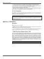
MB-700 as a TCP/IP Master ........................................................................................................................ 5.12
Description ................................................................................................................................................................5.12
1 - MB-700 working as Bypass (Serial to TCP) .........................................................................................................5.12
Configuration .............................................................................................................................................................5.13
2 - MB-700 working as Peer-to-peer .........................................................................................................................5.15
MB-700 as a TCP/IP Modbus Slave............................................................................................................ 5.16
1- MB-700 working as Concentrator..........................................................................................................................5.16
Using the Data Logger ................................................................................................................................ 5.17
Description ................................................................................................................................................................5.17
Configuration .............................................................................................................................................................5.17
Putting CCDL Blocks in Cascade ..............................................................................................................................5.19
Chapter 6 - SCENARIOS ...................................................................................................................6.1
Multiple Masters TCP/IP Communicating directly with several LC700s, including via Radio .............. 6.1
Multiple Masters TCP/IP Communicating directly with several LC700s and “Peer-to-peer” between
LC700s within a same Modbus RTU Network.......................................................................................... 6.2
Multiple Masters TCP/IP Communicating Directly with several LC700s and “Peer-to-peer” between
LC700’s of Different Modbus RTU Networks ........................................................................................... 6.3
Multiple Masters TCP/IP Communicating Directly with LC700s, “Peer-to-peer” and Network
Redundancy ................................................................................................................................................ 6.4
MB-700 as a Concentrator and Supervision via DFI OPC Server............................................................. 6.5
MB-700 working as a Concentrator and Supervision via DFI OPC Server and “Peer-to-peer” ............ 6.6
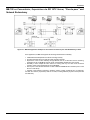
MB-700 as Concentrator, Supervision via DFI OPC Server, “Peer-to-peer” and network redundancy6.7
Multiple MODBUS RTU Masters Accessing a LC700 through only one Port (P2) .................................. 6.8
Chapter 7 – REDUNDANCY HOT STANDBY ...................................................................................7.1
Complete Redundant System Architecture ................................................................................................ 7.1
MB-700 Module Redundancy ....................................................................................................................... 7.2
Terminology ................................................................................................................................................................7.2
System Pre-requirements............................................................................................................................. 7.2
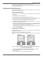
Configuring the Network Redundancy........................................................................................................ 7.3
Configuring the Workstation ........................................................................................................................................7.3
Configuring the DFI OLE Server..................................................................................................................................7.3
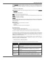
Configuring Hot Standby Redundancy ....................................................................................................... 7.4
First Time Configuration Procedure.............................................................................................................................7.6
Changing Configuration...............................................................................................................................................7.7
Replacing a Module with Failure .................................................................................................................................7.7
Correcting a Failure in the Synchronism Channel .......................................................................................................7.7
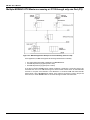
Firmware Update without Process Interruption ......................................................................................... 7.7
Adding Redundancy to an Existing System............................................................................................... 7.8
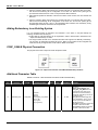
SYNC_CABLE Physical Connection ........................................................................................................... 7.8
Additional Parameter Table.......................................................................................................................... 7.8
Description of Meaning of RED_BAD_CONDITIONS_L / R Bits ............................................................. 7.10
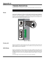
Appendix A - TROUBLESHOOTING................................................................................................ A.1
Reset.............................................................................................................................................................. A.1
Factory Init .................................................................................................................................................... A.1
HOLD Mode ................................................................................................................................................... A.1
When to Use the Factory Init/Reset Procedure ......................................................................................... A.2
VI
Summary
Appendix B - CABLING .................................................................................................................... B.1
Ethernet Cable Specification....................................................................................................................... B.1
Serial Cable Specification ........................................................................................................................... B.1
EIA-232 Interface ....................................................................................................................................................... B.1
Connecting the MB-700 to the LC700 ........................................................................................................................ B.4
EIA-485 Interface ....................................................................................................................................................... B.6
Dimensions ................................................................................................................................................... B.7
Appendix C – SPECIFICATIONS FOR MB-700 ............................................................................... C.1
Technical Specifications ............................................................................................................................. C.1
Block Minimum Configuration Table for the MB-700................................................................................ C.2
Data Types Available for the Parameter DATATYPE ................................................................................ C.2
Scale Conversion ......................................................................................................................................... C.3
Data Structure for MB-700 ........................................................................................................................... C.4
Block Structure – DS-64 ............................................................................................................................................. C.4
Value & Status - Floating Point Structure – DS-65 ..................................................................................................... C.4
Valor & Status – Discrete Structure – DS-66 .............................................................................................................. C.4
Mode Structure – DS-69 ............................................................................................................................................. C.4
Alarm Discrete Structure – DS-72 .............................................................................................................................. C.5
Event Update Structure – DS-73 ................................................................................................................................ C.5
Slave Address Structure- DS-263 .............................................................................................................................. C.5
Address Structure - DS-264 ....................................................................................................................................... C.6
Address Structure - DS-265 ....................................................................................................................................... C.6
Address Structure - DS-266 ....................................................................................................................................... C.6
Address Structure - DS-267 ....................................................................................................................................... C.6
Appendix D – SRF – SERVICE REQUEST FORM .......................................................................... D.1
VII
MB-700 – User’s Manual
VIII
Glossary
GLOSSARY
Address of a MODBUS Variable:
It refers to the address of the MODBUS variable read or written in an I/O block of a device.
Baud Rate:
Data transference rate in bits per second.
Bridge:
A bridge isolates two networks. It has the function of only passing the data addressed to it to the
other side. It works in the data link layer.
Bypass:
When the MODBUS message is received by the MB-700 it is passed to the other network where it is
connected.
CCCF:
Block that configures the communication between the MB-700 and slave devices.
CCCM:
Block to configure the peer-to-peer communication.
CCSM:
Block to configure the concentrator function of the MB-700.
CCDL:
Block that sets the Data Logger.
Communication Protocols:
They are rules to control the data communication. Protocol is the software that controls and grants
the communication, formats the way of sending data, defines the path, the sending and the
reception of data, check for transmission errors.
Configuration:
Establishes the functioning parameters for the device.
Data Concentrator:
The MB-700 is a data concentrator because it stores variables read from MODBUS slave devices in
its memory and makes them available to the supervision system and/or monitoring, avoiding these
systems needing to access slaves of the network directly.
Download:
It means in the MB-700 context, to send configuration or firmware to a device.
EIA-232/EIA-485:
Establish the standards for cable (physical connection) to serial communication.
Ethernet:
IEEE 802.3 Standard. It refers to the physical mean where it is installed the local network. The baud
rate may reach up to 10 Mbits/second.
Fast - Ethernet:
Operates at 100 Mbits/second and it is similar to the Ethernet. However, it is limited in 100 meters
by the distance between HUB and workstation.
IX
MB-700 – User’s Manual
Function Blocks:
Device language programming of industrial automation. To each function block it is associated an
algorithm and configuration parameters associated. The change of information between blocks will
be done through links between inputs and outputs of the function blocks.
Gateway:
Protocol converters, they work in the layer 4 of the OSI model.
Hub:
It is a connection concentrator. Each element of the local network is connected to a HUB, isolating
and helping error detection.
HSE:
High Speed Ethernet. Physical media of the protocol TCP/IP.
I/O:
It refers to the physical inputs and outputs of the logic controller where the data/information is sent
to the process and read from it.
IP Address:
The IP protocol handles the data sending in a network. Each element has an IP address used to
data communication. One IP address has 4 bytes. For example: 196.198.100.001.
Local Area Network (LAN):
It is the local network installed within a company, industry or institution, where these workstations
exchange information from each other.
Logic Controller:
Logical controller devices are microprocessor devices that allow creating control logic for process
automation.
Modem:
MODEM is a short for MOdulator DEModulator. The device makes the FSK (Frequency Shit
Keying), ASK (Amplitude Shift Keying) and PSK (Phase Shift Keying) modulation used to send
digital data through telephone lines or via electromagnetic irradiation.
Modbus:
Communication protocol used for devices used in an industrial environment.
Modbus RTU:
This is the MODBUS communication standard that uses physical means like EIA-232, EIA-485 or
radio. The main characteristic is supporting only one master.
Modbus/TCP:
MODBUS protocol that uses the TCP/IP layers supporting multi master mode.
Monitor/Monitoring
See and change read variables.
Modbus Address:
MODBUS address within a MODBUS network.
Modbus Master:
Device that supports the MODBUS protocol handling the master role. This type of device has the
ability to send commands to the MODBUS slave devices.
X
Glossary
MODBUS slave:
Device that supports the MODBUS protocol playing the slave role. This type of device only answers
to commands sent to it. It does not have the role of asking something from another device in the
network.
Modbus Variable:
Variables from Modbus slave devices available through communication.
Networks:
It is a set of devices connected to change information with each other.
OSI Model:
ISO model that establishes a standard to the data transference phases in networks. There are
seven levels in this model.
Level 7 - Application: Programs
Level l 6 - Presentation: Data Conversion
Level l 5 - Session: Establishing connection
Level 4 - Transport: Controls data transference
Level 3 - Network: Handles package sending, computing and transference of data
Level 2 - Data link Error management (detection and correction)
Level 1 - Physical: Specify the physical connection of network elements
Parameter:
Functioning, communication and storage characteristics of the MB-700.
“Peer-to-peer” Communication:
Communication way allowing changes of information between devices in the same hierarchic level.
In applications using MB-700, peer-to-peer means change of information between devices.
Router:
Router is responsible for sending the data packages through an external network until they reach
their destination. It works in the layer 3 of the OSI model.
Serial Communication:
Data is showed in the serial format, a succession of pulses, a waveform that forms the data to be
transmitted. Each bit is sent per time in one channel or way only.
Supervision System:
System located in the workstation where user may monitor and change field variable values and to
control process.
Switch:
Similar to bridge but allows that several sub nets interact with each other.
TCP/IP:
Communication protocol in local networks and external corporate networks. It has 4 layers:
• Network Layer: Protocols of layers 2 and 3 of the OSI model.
• Router Layer: The IP protocol routes data in the networks, but cannot grant communication done
properly.
• Transport Layer: TCP and UDP protocols transmit data routed in the previous layer to the next
layer.
• Application Layer: It is the equivalent to the layers 5, 6 and 7 of the OSI model. This layer
includes ftp, SMTP, Telnet, etc.
XI
MB-700 – User’s Manual
Transmission media:
It is the physical media, where the port is sent.
Transmitter:
Device that includes both the electronic board and the transducer/sensor that sends the field
variable read from this device.
XII
References
REFERENCES
-
Function Blocks Instruction Manual
-
Syscon Manual
-
LC700: User’s Guide
-
LC700: LC700 Configuration Manual
XIII
MB-700 – User’s Manual
XIV
Chapter 1
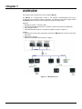
OVERVIEW
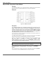
This manual presents instructions of how to install the MB-700.
The MB-700 is a microprocessor module. It has Ethernet, EIA-232/EIA-485 ports plus a
synchronism port that might be used for redundancy. The MB-700 uses a power supply PS-AC-R.
The MB-700 system consists of a CPU module plus this power supply module.
Hardware
9 Backplane R-700-4A – Rack with 4 Slots.
9 Processor Module MB-700 Processor 1x10 Mbps, 1xSYNC, Serial Ports EIA-232/EIA-485.
9 Power Supply PS-AC-R.
9 Cable Standard Ethernet DF54 – Twisted-Pair (100 Base T) Cable – length 2 m.
Software
9 DFI OLE Server (Used during configuration and when the MB-700 is set as a data concentrator)
9 System302
9 DHCP Server (optional)
9 Windows NT workstation (Service Pack 3 or higher)
Figure 1.1 – MB-700 Overview
1.1
MB-700 – User’s Manual
Main Characteristics
MB-700 has a double function: it is both a bridge between Ethernet and Modbus networks and a
data concentrator device.
The MB-700 has a modular concept and may be put in panels inside a control room or in sealed
boxes in the field. It is indicated to remote applications avoiding that user needs to walk to the place
where the process is located to configure the MODBUS device. User only needs to connect his
workstation or Human Machine Interface (HMI) to the network and configures the logic controllers
through the network. MB-700 handles the communication and conversion between protocols. It may
be set to act as a data concentrator, collecting data from field devices connected to the MODBUS
slaves. Its monitoring system or supervision system may access all this collected data directly on
the MB-700 memory, instead of accessing these data directly from Field.
It is a multi function module mounted in a backplane connected in a DIN rail where it is also
connected a PS-AC-R power supply module. Modularity is the key for flexibility of the MB-700.
Connections of source and SYNC channel (redundancy function) are done using plug-in connectors,
making removing safe and easy. Connectors have an advantage, they cannot be connected in a
wrong way, avoiding that high voltages are applied to a low voltage terminal. The power supply
module has diagnostic LEDs to indicate normal operation or failure, what helps to solve troubles and
to diagnose, especially in a system with several units. It is possible to remove the fuse (accessible
externally located in the input) without the necessity to remove a source module or disconnect any
wire.
It is important to notice:
- One Backplane is required for each 4 modules;
- One flat cable is required to connect Backplanes; and
- MB-700 uses the DFI OLE Server. The license to the DFI OLE Server is available in different
levels with different capacities for supervision of function blocks.
1.2
Overview
System Integration
Advanced communication characteristics built in the MB-700 grant the system high integration:
-
Ethernet Port;
Modbus TCP/IP;
Serial EIA-232 / EIA-485 Ports;
Modbus RTU; and
Supports up to 31 slaves connected to the EIA-485 bus.
Power Supply – PS-AC-R
This module is the power supply for the MB-700 and LC700 system. It supplies 5V necessary to the
IMB. This module has functions of diagnose and dedicated LEDs that indicate normal operation in
failure conditions what makes possible troubles to be easily detected, especially in systems with
several units. It is easy to check a power supply module with defects in a panel with several
modules. It is possible to replace the fuse (located on the input with external access) without
needing to remove the source module or disconnect any wire. The output is protected against short
circuit and it is not damaged even in lasting short circuits.
Processor Module – MB-700
Based in a 32-bit RISC processor and firmware stored in a Flash memory, this module handles
communication and control tasks.
- 1 Ethernet Port @ 10Mbps
- 1 SYNC Port @ 31,25Kbps
- 1 EIA-232/EIA-485 Port @ 9,6 Kbps – 115,2 Kbps
- CPU Clock @ 25MHz, 2MB NVRAM
Open Protocols
Ethernet
Implements the Smar Ethernet protocols (SE) and MODBUS based on TCP/IP and may coexist with
other Ethernet protocols.
Modbus RTU: EIA-232 and EIA-485
Using these ports, the MODBUS protocol connects data from a MODBUS network with the local
area network. These ports may be connected to a device network (EIA-485) or connected to
controllers through a modem or a radio link. Supports up to 31 slaves connected in each serial port
using the EIA-485 standard.
Configuration
MB-700 is completely configured using the configuration tool (for example, SYSCON) through
TM
function blocks available in the FOUNDATION Fieldbus Standard.
Supervision
The use of these technologies like OPC (OLE for Process Control) makes the MB-700 a flexible
TCP-IP/MODBUS interface. The OPC Server allows the MB-700 to be connected to any supervision
package. The only requirement is that there is an OPC client to the package, so user can connect
the MB-700 with the best supervision interfaces available.
1.3
MB-700 – User’s Manual
1.4
Chapter 2
INSTALLATION
ATTENTION: If any of the steps are not followed, it may cause a malfunctioning of the system.
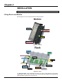
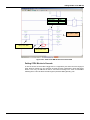
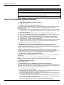
Fixing Racks and Modules
Note the Figures 2.1 and 2.2 and proceeds according instructions.
Module
LEDs
Introduction to
connect-tag
RS-232 and Ethernet
Interfaces
Terminals
Screw for fixation of
the module to the rack
Figure 2.1 - Module
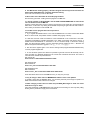
Rack
A. Joining the
Rack
C. Module
support
L. Connetion of the Rail
B. Jumper
W1
K. Digital Ground
D. DIN Rail
Slot 0
Slot 1
J. Flat Cable
Slot 2
Slot 3
E. Flat Cable
connector (Sup)
I . Flat Cable
Connector (Inf)
H. Clips
G. Rack Address
Switch
F. Module
Connector
Figure 2.2 – Rack
A. Joining the Rack - When assembling more than one rack in a same DIN rail, use a special
metallic piece to link one rack to the other. This connection generates stability to the assembly and
makes possible the digital ground connection (K)
2.1
MB-700 – User’s Manual
B. Jumper W1 – when connected, it allows that rack to be powered by the previous rack
C. Module support – piece of the superior part of the rack
D. DIN Rail - Base to fix the rack. It must be fixed tightly in the place of the rack mounting
E. Flat Cable Connector (Superior) – When there are more than one rack in the same DIN rail,
they must be hooked up by a flat cable (J) connected to the Flat Cable connectors (J) and (E)
F. Module Connector – Bottom part of the module in the rack
G. Rack Address Switch – This address switch allows to address more than one rack in the same
DIN rail, giving distinguish addresses to the racks
H. Clips - Used to fix rack in the DIN rail
I. Flat Cable Connector (Inferior)– When existing more than one rack in the same DIN rail, they
must be hooked up by a flat cable (J) connected to the Flat Cable connectors (J) and (E)
J. Flat Cable – Cable used for connecting the data bus between the racks
K. Digital Ground – When there are more than one rack in the same DIN rail, the connection
between digital grounds (k) must be reinforced through appropriate metallic piece
L. Connection of the Rail – Support to fix the rack and the DIN rail (D).
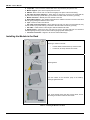
Installing the Module in the Rack
Mounting a module in the rack:
o
o
Find the border located at the top of the free slot.
Fit the hole, at the top back of the module.
Mounting detail.
Lock the module in the connector (slot) of the IMB by
pushing it against the rack.
Next, fix the module at the rack using a screw driver, and fix
the locking screw at the bottom of the module.
Table 2.1 – Installing the Module in the Rack
2.2
Installing
Installing the Rack in the DIN Rail
• Locate the clips on the bottom of the Rack
• Use a screw-driver to pull them down
• Place the back of the rack on the top of the DIN rail edge
• Accommodate the Rack on the DIN rail and push the clips up. The user will hear a click sound
when they lock properly
• Set the correct address for the rack using the rotary switch at the rack
NOTE
The addresses can NOT be repeated.
Adding Racks (Local I/O Expansion)
Local I/O Expansion is the process of adding more racks connecting them through the Rack. For
this purpose, use a flat cable. Different sizes are available to reach different situations.
• Connect the new rack with the previous one by using a selected flat-cable
• Don’t forget to place a terminator in the last rack
• Set the address for the new rack using the rotary switch
TIPS for the Assembly
If there is more than one rack, follow the tips below:
• Do the fixation in the DIN rail at the end of the assembly
• Keep the slot 3 free in the rack, to be able to establish connection to the next module for the
connector of flat cable
• Verify intently the address configuration (addressing key), as well as the Jumper W1 and the
BUS cable
• Remember that to give continuity to DC power supply of previous rack, connect the jumper W1
• Make the amendment of racks and strengthens the digital ground of the hardware
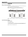
Installing the Hardware
Operating Range
0º C - 60º C
32º F - 140º F
OUTPUT
24VDC
300mA
2B
CAUTION
Fail
V
90-264VAC
Max 72VA
50/60Hz
Operating Range
0º C - 60º C
32º F - 140º F
OUTPUT
24VDC
300mA
1B
12VA
115VAC Max.
200mA Max.
Air convection
do not obstruct
air flow!
AC-R/50
AC Power Supply for Backplane
Air convection
do not obstruct
air flow!
AC-R/50
AC Power Supply for Backplane
See the details of the frontal view of the modules, as the Figure 2.3 below.
1B
2B
12VA
115VAC Max.
200mA Max.
3B
4B
5B
6B
CAUTION
90-264VAC
Max 72VA
50/60Hz
3B
4B
5B
6B
7B
7B
FUSE
FUSE
1.25A
1.25A
See
manual
Fail
V
See
manual
Figure 2.3 – MB-700 Hardware Basic System
To wire the MB-700 and HUB uses a standard twisted-pair cable. The MB-700s have simple RJ-45
connectors. No special tools or skills are required. Installation is simple and very fast.
2.3
MB-700 – User’s Manual
Frontal LEDs indicate active communication or failure. The user can connect and disconnect the
modules without having to power down. Using HUB/Switch can disconnect the devices without
disrupting control or communication of other nodes.
There are two types of cables: the DF54 cable enables the connection MB-700/HUB, or the DF55
cable enables the direct connection MB-700/PC. See the Appendix B for further details.
Basic installation tips:
1. Connect the two modules (PS-AC-R and MB-700)
2. Connect the AC line in the input of the PS-AC-R
3. Plug the Ethernet cable (standard pair cable) connecting MB-700 to the HUB/Switch
4. The MB-700 will automatically get an IP address from the DHCP server, but if this server is not
available, it will initially have a fixed IP address (this fixed IP may be changed through the FBToolssee topic “Connecting the MB-700 to the Subnet”)
Using the Fault Indication
The 1B and 2B terminals available in the MB-700, may be used in a Fault Indication application.
Actually, these terminals are only a NC Relay.
The NC Relay supports:
0.5A @ 125VAC
0.25A @ 250VAC
2A @ 30VDC
Normally, MB-700 forces this relay to remain open but if any bad condition crashes the Processor,
the hardware will close the relay. This status may be used in redundancy situation, where the
backup Processor reads this contact and knows about the fault. Other possibility is using this
contact to turn on an alarm.
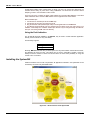
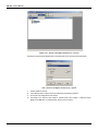
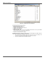
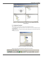
Installing the System302
Install the software from the CD of System302. All applications included in the System302 can be
accessed by the shortcut “System302 Browser“.
Figure 2.4 – Shortcut Screen of the System302
2.4
Installing
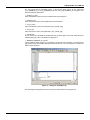
Getting the License for DFI OLE Server
There are two ways to get a license to use the DFI OLE Server. There is the Hard Lock protection
version (Hard key) and the software version (SoftKey).
The Hard key is already ready for use, it is only necessary to connect the device in the parallel port
of the PC.
To use protection through software it is required to get a License key getting in touch with SMAR.
Use the application tool GetLicense.exe located on the Smar’s working directory (usually
“drive:\Program Files\Smar\OLEServers\Getlicense.exe”), or directly through the shortcut “Get
License” in the SMAR directory/Browser (see previous picture).
From the information created in this application fill the form FaxBack.txt and send it to Smar to get
license to use the SYSCON and/or DFI OLE Server. See the Figure 2.5.
Figure 2.5 – Get License Screen
When the user receives a reply from Smar with the License Keys, should type the codes in the blank
fields (see figure above). Press the “Grant License Keys” button. In case the codes are accepted, a
success confirmation message will appear. The DFI OLE Server and SYSCON are ready to use.
Connecting the MB-700 to the Subnet
The environment with MB-700 involves a network (Subnet) where it is necessary the IP address for
each connected device.
The solution for this attribution is a DHCP (Dynamic Host Configuration Protocol SERVER)
server. It will handle the IP attribution dynamically to each device, avoiding any troubles like equal IP
addresses to two different devices.
ATTENTION
To connect more than one MB-700, the following steps must be completely executed to each MB700
1. Plug the Ethernet cable DF54 of the MB-700 module to the Switch (or HUB) of the subnet where
the MB-700 will be put.
OBS- For point to point connections (the MB-700 connected directly to the PC) use the cross cable
DF55.
2. Turn the MB-700 module on. Be sure that the ETH10 LED and the Run LED are on.
2.5
MB-700 – User’s Manual
3. Keep the push button on the left pressed tightly (Factory Init/Reset) and next press the push
button on the right three times, certifying that the FORCE LED blinks three times per second.
NOTE: if the counting of how many times the push button at right was pressed was lost, check the
number of times the FORCE LED blinks per second. It will blink again once per second after the
fourth touch (in another words this function is cyclic).
4. Release the left push button and the system will execute the RESET. Subsequently it will execute
the firmware with the standard values for IP address and the Subnet Mask.
5. If the network has a DHCP server (consult the administrator of the network for details) the MB700 is already connected to the Subnet. Otherwise it will have an IP address 192.168.164.100 and
the user will have to execute the next steps:
6. If the user is following this step the network does not have a DHCP server. Thus it will temporarily
change the IP address of the Workstation (it is recommendable to have network management
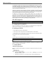
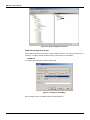
knowledge). Enter the Control Panel (Windows Control Panel) and choose the option Network.
NOTE: In case the Network option in the control panel does not have the TCP/IP protocol, use the
Windows to proceed with the installation.
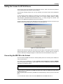
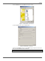
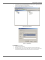
7. Choose the Internet Protocol option (see Figure 2.6 below) and click the Properties button.
Figure 2.6 – Change of the IP Address
8. Write down the original IP address and the subnet mask of the workstation so the user will be
able to restore them at the end of this operation.
9. Change the IP address and the subnet mask of the PC so it is located in the same Subnet of the
MB-700. Preferable the IP addresses used must be supplied by the Network administrator.
NOTE
Values must be of the type: IP Address 192.168.164.XXX and subnet mask 255.255.255.0. Keep
the value for Default Gateway.
ATTENTION
Do not use the address 192.168.164.100 once it is the default address used by the MB-700.
10. Click the OK button.
11. Run the FBToolsWizard.exe (located in the working directory of Smar) directly from the shortcut
“FBTools Wizard”, or directly using the shortcut “FBTools Wizard”.
2.6
Installing
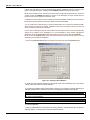
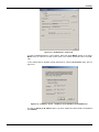
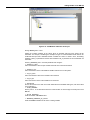
12. Select the MB-700 device and click Next. See the Figure 2.7 below.
Figure 2.7 – FBTools Wizard – Choose Device
13. Click the Connect button to see the available modules.
Figure 2.8 – Dfi Download – Connect (1)
14. Select the target MB-700 module in the option Module using as reference the serial number
(refer to the external identification label of the MB-700).
ATTENTION
If the user does not follow this step this might imply in serious consequences.
2.7
MB-700 – User’s Manual
Figure 2.9 – Dfi Download – Choose Module
15. To go ahead it is necessary to stop the firmware that is running in the MB-700 Processor. Click
the HOLD button.
16. After executing the previous step, the module will not running the firmware so it will stop all its
activity. Confirm the operation by clicking the Sim button.
Figure 2.10 - Dfi Download – Entry Confirmation Screen in Hold Mode
17. Be sure the HOLD LED is ON. After stopping the firmware execution in the module, the window,
represented by Figure 2.11, will appear again.
2.8
Installing
Figura 2.11 – Dfi Download – Connect (2)
18. Click the Connect button to return network. Select the target MB-700 module in the option
Module using as reference the serial number (refer to the external identification label of the MB700).
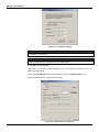
19. The default option is attribution through DHCP Server. Click the IP Properties option. See the
Figure 2.12.
Figure 2.12 – IP Address Screen – Attribution of the IP Address from DHCP Server
20. Click the Specify an IP address option. Type the IP address and subnet mask to be attributed
to the MB-700.
2.9
MB-700 – User’s Manual
Figure 2.13 – IP Address - Specify
ATTENTION
Do not use the IP 192.168.164.100 once it is the default address used by the MB-700. Be certain
this address is not being used.
TIP
Take note of the IP address attributed and relate them to the serial numbers of each module. This
will help during identification and diagnose of the possible failures.
21. Click OK to end this operation.
22. Now return to the screen TCP/IP properties of the PC and restore the original values of IP
address and subnet mask.
23. After giving the MB-700 a new IP, the process will be back to the Dfi Download screen.
24. Click the Run button to execute the firmware again.
Figure 2.14 - Dfi Download – Connect (3)
2.10
Installing
25. Click the Close button in the Dfi Download screen to finish the operation of IP attribution.
26. In the DOS prompt type C:\>arp –d 192.168.164.100 <enter> (see note below).
27. End of connection procedure of the MB-700 in the subnet.
NOTE
If it is necessary to set more than one MB-700, run the following command to clear the ARP table,
before setting the next MB-700.
C:\>arp –d 192.168.164.100 <enter>
2.11
MB-700 – User’s Manual
2.12
Chapter 3
CONFIGURATION
Updating the Firmware
1.
Plug the Ethernet cable DF54 of the MB-700 module to the Switch (or HUB) of the subnet
where the MB-700 will be put.
OBS: For point to point connections (the MB-700 connected directly to the PC) use the cross cable
DF55.
2.
Turn the MB-700 module on. Be sure that the ETH10 LED and the Run LED are on.
3.
Keep the push button on the left pressed tightly (Factory Init/Reset) and next press the push
button on the right three times, certifying that the FORCE LED blinks three times per second.
NOTE: if the counting of how many times the PUSH BUTTON at right was pressed was lost, check
the number of times the FORCE LED blinks per second. It will blink again once per second after the
fourth touch (in another words this function is cyclic).
4. Release the left push-button and the system will execute the RESET. Subsequently it will execute
the firmware with the standard values for IP address and the Subnet Mask
5. If the network has a DHCP server (consult the administrator of the network) the MB-700 is
already connected to the Subnet. Otherwise it will have an IP address 192.168.164.100 and the user
will have to execute the next steps.
6. If the user is following this step the network does not have a DHCP server. Thus it will temporarily
change the IP address of the Workstation (it is recommendable to have network management
knowledge). Enter the Control Panel (Windows Control Panel) and choose the option Network.
NOTE: In case the Network option in your control panel does not have the TCP/IP protocol, use the
Windows to proceed with the installation.
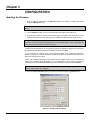
7. Choose the Internet Protocol option (see Figure 3.1 below) and click the Properties button.
Figure 3.1 - Change of the IP Address
3.1
MB-700 – User’s Manual
8. Write down the original IP address and the subnet mask of the workstation so the user will be
able to restore them at the end of this operation.
9. Change the IP address and the sub net mask of the PC so it is located in the same Subnet of the
MB-700. Preferable the IP addresses used must be supplied by the Network administrator.
NOTE
Values must be of the type: IP Address 192.168.164.XXX and subnet mask 255.255.255.0. Keep
the value for Default Gateway.
ATTENTION
Do not use the address 192.168.164.100 once it is the default address used by the MB-700.
10. Click the OK button.
11. Run the FBToolsWizard.exe (located in the working directory of Smar) directly from the shortcut
“FBTools Wizard”, or directly using the shortcut “FBTools Wizard”.
12.Select the MB-700 device and click Next.
Figure 3.2 – FBTools Wizard – Choose Device
13. Click the Connect button to see the modules are available.
3.2
Configuring
Figure 3.3 – Dfi Download – Connect (1)
14. Select the target MB-700 module in the option Module using as reference the serial number
(refer to the external identification label of the MB-700).
ATTENTION
If the user does not follow this step this might imply in serious consequences.
Figure 3.4 – Dfi Download – Choose Device
15. To go ahead it is necessary to stop the firmware that is running in the MB-700 Processor. Click
the HOLD button.
16. After executing the previous step, the module will not running the firmware so it will stop all its
activity. Confirm the operation by clicking the Sim (Yes) button.
3.3
MB-700 – User’s Manual
Figure 3.5 – Dfi Download – Entry Confirmation Screen in Hold Mode
17. Be sure the HOLD LED is ON. After stopping the firmware execution in the module, the window
will appear again (See Figure 3.6).
Figure 3.6 – Dfi Download – Connect (2)
and choose the firmware to download. After choosing the firmware, the
18. Click the button
following window will open.
Figure 3.7 – Dfi Download – Choose the Firmware
3.4
Configuring
ATTENTION
If this step is not followed, it might imply in serious consequences.
19. Click the Download button. The following dialog will appear (Figure 3.8).
Figure 3.8 – Download Firmware Confirmation
20. To start the firmware again, click the Sim (Yes) button.
21. During the download, it shows the progress indication bar. See Figure 3.9.
Figure 3.9 – Dfi Download – Progress Screen
22. When the download ends, it shows a status message. At this moment, the MB-700 will be on
Run mode. Click the OK button. (Be sure the RUN LED is lit).
Figure 3.10 – Dfi Download – Concluded Download
23. To finish this operation, click the Close button.
3.5
MB-700 – User’s Manual
Figure 3.11 – Screen to Finish Operation
Setting the MB-700 through Software
ATTENTION
To have the MB-700 properly set by SYSCON it must be assured the procedure “Connecting the
MB-700 to the Subnet” was done properly.
The MB-700 is totally set through Function Blocks available in the Fieldbus Foundation standard.
Figure 3.12 – Initial Configuration - Syscon
The MB-700 works together with the SYSCON, configuration and maintenance software, to use the
plug and play characteristic allowing to detect, identify and attribute addresses to devices
3.6
Configuring
connected, removed or that have trouble. Once it is connected to the Ethernet bus or to a
Workstation, the MB-700 is detected and next it is attributed a fixed IP address or variable
depending on the process set via FBTools, eliminating any troubles with the dip switches or address
duplication.
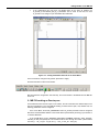
Creating a New Plant
Certify to have installed the System302 package that contains the Syscon.
1.
Once the Syscon is installed, run the application.
Figure 3.13 – Software Syscon
2.
In the main window, choose Project File Æ New. See the Figure 3.14 below.
Figure 3.14 – Main Screen – Software Syscon
3.
Choose Projects and give a new name to the new plant.
4.
Initially, it must configure to use the DFI OLE Server.
5.
In the project toolbar, click the Fieldbus Networks option to configure the server. In the main
window, choose Communication Æ Settings.
3.7
MB-700 – User’s Manual
Figure 3.15 – Screen to Configure the Server (1) – Syscon
6. Select the name Smar.DFIOLEServer0 in the parameter Server ID and click the OK Button.
3.16 – Screen to Configure the Server (2) – Syscon
7.
8.
9.
10.
3.8
Add the Fieldbus channel
In the MB-700 device, add the CCCF (Configuration) and Resource Blocks.
Do the Off Line configuration of the device.
According to the process, add CCSM or CCCM blocks. See Chapter 4 “Adding Function
Blocks to the MB-700”. For further details, see the Syscon manual.
Chapter 4
MB-700 FUNCTION BLOCKS
Block CCCF- Concentrate Configuration
Overview
This block allows configure several communication parameters of the Modbus protocol.
Description
This block allows setting parameters of the communication between MB-700 and Modbus slave
devices through Ethernet and serial (EIA-232/EIA-485) ports. User defines the baud rate for serial
ports, parity, timeout, number of retransmissions and bypass direction.
IMPORTANT
User must set ONLY one CCCF Block for each device.
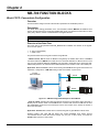
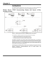
Direction of the Data Flow
User must also set the parameter BYPASS_DIRECTION to establish the direction of the bypass.
There are two options:
9
9
0: TCP to serial (default)
1: Serial to TCP
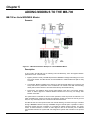
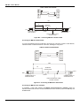
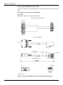
The pictures below show two bypass scenarios using MB-700:
- TCP/IP to Serial: MB-700 works as Modbus TCP gateway for Modbus RTU. When a MODBUS
command reaches the MB-700 via TCP/IP and the command addresses a different device of the
one set in the parameter DEVICE_ADDRESS, this command is transmitted in the serial ports (EIA232/EIA-485).If there is an answer from the addressed device this answer is sent in the TCP/IP port.
Application: Master MODBUS TCP/IP communicating with MODBUS RTU typical slave devices for
supervision, configuration; or MB-700 working as data concentrator or peer-to-peer.
PC with
Ethernet Adapter
Ethernet
MB-700
RS-232
MB-700
MB-700
DFI302
RS-485
MB-700
LC700
Figure 4.1 – MB-700 Configuration Example as Serial Master
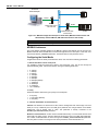
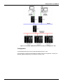
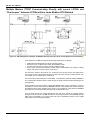
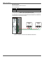
- Serial to TCP/IP: Selecting this option the MB-700 will work as a serial slave device (EIA-232 or
EIA485) and as TCP/IP master. One MODBUS RTU command that reaches the MB-700 via serial
(EIA-232/EIA485) will be sent in the TCP/IP port. If there is an answer in the TCP/IP, the answer is
sent in the serial ports.
Application: MODBUS RTU master device communicating with a typical Modbus TCP/IP slave.
Working together with other MB-700 allows that several MODBUS RTU master devices
communicate with the same slave device through only one port. In other words, it converts the
MODBUS RTU protocol in multi master.
4.1
MB-700 – User’s Manual
PC without
Ethernet Adapter
MB-700
MB-700
Data flow direction:
Serial to TCP
DFI302
Ethernet
RS-232
MB-700
RS-485
MB-700
Data flow direction:
TCP to Serial
LC700
Figure 4.2 – MB-700 Configuration Example as Serial Slave (MB-700 Communication with
Work Station) and Serial Master (MB-700 Communication with LC700)
NOTE
For this scenario, MB-700 does not support CCSM and CCCM Blocks.
MODBUS Addresses
User must attribute a Modbus address to the MB-700. However this address must be unique in the
Modbus networks where the MB-700 is connected through Ethernet or serial ports. In this case, user
must set the DEVICE_ADDRESS parameter. The default value for this parameter is 247.
Configuring the Serial Media
In applications where the serial port of MB-700 is used, user must set the following parameters:
1 - Rate of transference of the serial ports
It is possible to select the baud rate of data in the serial ports. They may be set through the
parameter BAUD_RATE. It allows the selection among the following baud rates:
9
9
9
9
9
9
9
9
9
9
9
0: 100 bps
1: 300 bps
2: 600 bps
3: 1200 bps
4: 2400 bps
5: 4800 bps
6: 9600 bps(default)
7: 19200 bps
8: 38400 bps
9: 57600 bps
10: 115200 bps
2 - Parity
Parameter PARITY defines the type of parity to the serial ports.
9
9
9
0: No parity
1: Even Parity (default)
2: Odd parity
3 – Timeout and Number of retransmissions
Timeout: time waited for an answer from a slave, after a message has been sent through one of the
serial (P1 or P2) or Ethernet ports. The TIME_OUT parameter can change between 0 and 65535
milliseconds, and its default value is 1000. This parameter is directly connected to the
NUMBER_RETRANSMISSIONS parameter.
Number of retransmissions: number of times the MB-700 will retry to communicate with the slave
device after not getting a reply. The time waited for this answer is set in the TIME_OUT parameter.
The number of retransmissions is chosen through the NUMBER_RETRANSMISSIONS parameter.
User may select a value in the range 0 to 255 to this parameter, and its default value is 1.
4.2
MB-700 Function Blocks
For the Bypass function, the NUMBER_RETRANSMISSONS parameter is not applied.
4 – RTS/CTS
For devices that require RTS and CTS signals, user can enable or disable this option. In the
RTS_CTS_TIMEOUT parameter, user sets the maximum time for waiting the CTS after the RTS
has been sent. If the RTS_CTS_TIMEOUT parameter is equal to 0, this function will be disabled.
The default value is 0 (disabled).
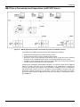
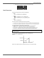
5 –Time delay between Rx and Tx
Optionally, an extra time between the end of receiving (Rx) and the beginning of the next serial
transmission (Tx) can be set. The TIME_DELAY parameter defines the time, in milliseconds, of the
delay time. This delay time is used when the device (master or slave) has slowness in the serial
processing.
If MB-700 acts as Serial Master, the delay will be between a slave answer and the next MB-700
request.
Figure 4.3 – Time Delay between Rx and Tx (MB-700 as Serial Master)
If MB-700 acts as Slave Serial, the delay will be between the Master request and MB-700 answer
for the Master.
Figure 4.4 – Time Delay between Rx and Tx (MB-700 as Slave Serial)
Configuring the TCP Media
For the applications where MB-700 is used as Modbus TCP Master, the following parameters must
be set:
•
If there is a TCP slave with a unique Modbus address, the SLAVE_ADDRESSES parameter
must be used, which the IP address of the Slave is configured (IP_SLAVE_1 to IP_SLAVE_6)
and the respective Modbus Address of the Slave (MODBUS_ADDRESS_SLAVE_1 to
MODBUS_ADDRESS_SLAVE_6);
•
If there are many Modbus Slaves for the same IP address, the IP_SLAVE_x parameters with
the respective Modbus addresses of the slaves DEVICE_IDS_IP_x must be used (where x
means the parameters 7 to 12).
For further details about this configuration type, refer to the Chapter 5 “Adding Blocks to the MB700”.
Scan Cycle
The scan cycle of supervision blocks and control may be set through the parameters
SUPERVISION_OFF_DUTY and CONTROL_OFF_DUTY. Parameter SUPERVISION_OFF_DUTY
indicates the time in milliseconds of the delay (between readings) during the supervision scan (block
CCSM). In the same way, parameter CONTROL_OFF_DUTY indicates the delay during scan of
control (CCCM).
Note
When MB-700 acts as bypass or there are written commands for Supervision, these commands
has priority over the supervision and control scan and they don’t follow the OFF_DUTY times.
4.3
MB-700 – User’s Manual
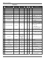
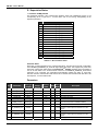
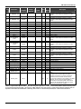
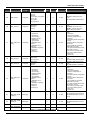
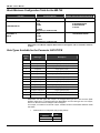
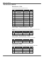
Parameters
Idx
Parameter
Data Size
(length)
1
ST_REV
2
3
4
Valid Range/
Options
Default
Value
Unit
Store /
Mode
Unsigned16
0
None
S
TAG_DESC
OctString(32)
Spaces
Na
S
STRATEGY
Unsigned16
0
None
S
ALERT_KEY
Unsigned8
0
None
S
O/S
Na
S
E
D / RO
1 to 255
5
MODE_BLK
DS-69
6
BLOCK_ERR
Bitstring(2)
7
REDUNDANCY_ROLE
Unsigned8
Not used
Main
E
S
8
REDUNDANCY_STATE
Unsigned8
Not used
Standby
E
D/RO
9
BAD_COMM
Boolean
Not used
TRUE
E
D / RO
10
BAD_COMM_STANDBY
Unsigned8
Not used
TRUE
E
D / RO
11
CHECK_COMM_STANDBY
Unsigned8
0-255
0
Na
S
12
DEVICE_ADDRESS
Unsigned8
13
SLAVE_ADDRESSES
DS-263
1-247
247
E
S
S
Description
See Mode Parameter
It specifies the preferable MB-700 to
be
Active,
when
there
is
redundancy.
It shows which MB-700 is Active
and which MB-700 is in Standby
mode.
It indicates if any slave Modbus
device scanned by MB-700 is not
communicating.
It indicates if the Standby is not able
to communicate with a slave device.
This parameter is configured to
Standby, if the communication test
between the slave equipment was
performed in TCP.
0: Disables the test.
1 – 255: Enables the test and
defines the time interval, in
seconds, between each test.
Define the device address in the
Modbus network when acting as a
slave.
IP number and corresponding
device address of slave device,
when accessed through Ethernet
TCP/IP.
14
BAUD_RATE
Unsigned8
0:110, 1:300,
2:600, 3:1200,
4:2400, 5:4800,
6:9600, 7:19200,
8:38400,
9:57600,
10:115200
15
STOP_BITS
Unsigned8
0:1, 1:2
1
E
S
It defines the number of stop bits for
serial ports.
16
PARITY
Unsigned8
0:None, 1:Even,
2:Odd.
Even
E
S
It defines the parity for serial ports.
17
TIMEOUT
Unsigned16
0-65535
1000
ms
S
18
RTS_CTS_TIMEOUT
Unsigned16
0-65535
0
ms
S
19
NUMBER_RETRANSMISSION
S
Unsigned8
0-255
1
20
SUPERVISION_OFF_DUTY
Unsigned16
0-65535
0
ms
S
21
CONTROL_OFF_DUTY
Unsigned16
0-65535
0
ms
S
4.4
9600
E
S
It defines the baud rate for serial
ports.
S
Time to wait a response from a
slave after sending the command in
the serial ports.
Specify the maximum time waiting
for CTS become active after setting
RTS in the serial ports.
Number of retransmission if MB-700
doesn’t receive response from
slave.
Time
between
supervision
commands.
The
zero
value
indicating that the OFF_DUTY is
disabled.
Time between control commands.
The zero value indicating that the
OFF_DUTY is disabled.
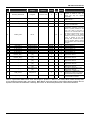
MB-700 Function Blocks
Idx
Parameter
Data Size
(length)
Valid Range/
Options
Default
Value
Unit
Store /
Mode
22
BYPASS_DIRECTION
Unsigned8
0: TCP to Serial
1: Serial to TCP
0
na
S
23
ON_APPLY
Unsigned8
0:None, 1: Apply
None
E
S
24
SCAN_TIME
Float
25
UPDATE_EVT
DS-73
Na
D
26
BLOCK_ALM
DS-72
Na
D
27
28
29
30
31
32
IP_SLAVE_7
IP_SLAVE_8
IP_SLAVE_9
IP_SLAVE_10
IP_SLAVE_11
IP_SLAVE_12
Spaces
Spaces
Spaces
Spaces
Spaces
Spaces
S
S
S
S
S
S
33
DEVICE_IDS_7
0
S
34
DEVICE_IDS_8
0
S
35
DEVICE_IDS_9
0
S
36
DEVICE_IDS_10
0
S
37
DEVICE_IDS_11
0
S
38
DEVICE_IDS_12
VisibleString(32)
VisibleString(32)
VisibleString(32)
VisibleString(32)
VisibleString(32)
VisibleString(32)
Array Unsigned8
[32]
Array Unsigned8
[32]
Array Unsigned8
[32]
Array Unsigned8
[32]
Array Unsigned8
[32]
Array Unsigned8
[32]
0
S
39
TIME_DELAY
Unsigned 16
0
40
TCP_SCAN_TIME
Float
D/RO
millise
c
S
D/RO
Description
Define the data direction. If the
direction is “Serial to TCP” the
device has only the Bypass
functionality.
Apply the changes made in the
Modbus blocks.
Scan Time of the Serial Modbus
This alert is generated by any
change to the static data.
The block alarm is used for all
configuration, hardware, connection
failure or system problems in the
block. The cause of the alert is
entered in the subcode field. The
first alert to become active will set
the Active status in the Status
attribute. As soon as the Unreported
status is cleared by the alert
reporting task, another block alert
may be reported without clearing
the Active status, if the subcode has
changed.
Slave IP address 7.
Slave IP address 8.
Slave IP address 9.
Slave IP address 10.
Slave IP address 11.
Slave IP address 12.
List of Device Ids Modbus for the
respective IP Slave 7.
List of Device Ids Modbus for the
respective IP Slave 8.
List of Device Ids Modbus for the
respective IP Slave 9.
List of Device Ids Modbus for the
respective IP Slave 10.
List of Device Ids Modbus for the
respective IP Slave 11.
List of Device Ids Modbus for the
respective IP Slave 12.
Waiting time, in milliseconds,
between the reception (Rx) and the
next transmission (Tx) of MB-700.
Time used for the Ethernet port to
scan the Modbus variables.
Table 4.1 - Legend: Store / Mode Column – Store: data storage (D – Dynamic; S – Static; N – Non volatile) / Mode: minimal necessary mode
for user modify the parameter (OOS – Out of Service, MAN - Manual); If the mode column is empty indicates that the parameter does not
depends on the mode to be modified. RO – Read Only; Unit Column - E – Enumerated parameter; Na – Dimensionless Parameter.
4.5
MB-700 – User’s Manual
Block CCSM - Concentrate Supervision Master
Overview
This block supplies information to monitor a Modbus slave device connected to the serial port of the
MB-700 with supervision functionality. This functionality is obtained remapping Modbus variables of
the Modbus device into parameters of this block.
Description
In this block user must inform to the MB-700 the MODBUS addresses of the devices in the
MODBUS network.
NOTE
The standard of the Modbus protocol specifies the division of the address range to the variables
•
0001 to 9999 Î Digital Outputs
•
10001 to 19999 Î Digital Inputs
•
30001 to 39999 Î Analog Inputs
•
40001 to 49999 Î Analog Outputs
The CCSM block allows user to view and change variables of the MODBUS addresses configured.
A - Configuring Points to be Supervised
MODE OF OPERATION
The MODE_BLK parameter sets the operation mode of this block. Modes supported by the CCSM
Block are “Auto” (automatic, i.e., normal operation) and OOS (Out of Service). The MODE_BLK
parameter is composed of: Target, Actual, Permitted and Normal. The target mode is the operation
mode set by user. “Actual” is the real operation mode of the block, because it displays the current
mode of the block.
Parameters of block configuration (like SLAVE_ADDRESS, B_ADDRESS, F_ADDRESS) cannot be
changed if the block is working in the automatic mode. To change parameters user must change
Target for “OOS” and only next change parameters of configuration and next change the operation
Target for “Auto”. After changing any parameter user will have to change the parameter On_Apply
(in the configuration block CCCF) to “Apply” so that these changes have effect. The block will
remain in OOS (MODE_BLK. ACTUAL= OOS) while the parameter ON_APPLY is not changed to
“Apply”.
NOTE
The column Store/Mode of the table of parameters of the CCSM block contains a list of
parameters that require the OOS mode to be set before these parameters are changed. For more
details please refer to the Function Blocks Manual.
SUPERVISION WAYS
1 - SCAN_BEHAVIOR Parameter:
User may select this parameter in two modes:
1- Using Config View
2- Not using Config View
If user sets the mode “1” will make the MB-700 to get the data from the slave devices in a much
faster and optimized way. This will increase the updating of parameters of these blocks that are
mapped in the Modbus slave devices.
NOTE
Smar devices only support mode “Using Config View”.
IMPORTANT
When the parameter SCAN_BEHAVIOR= “Usando Config View”, be sure the parameters of
percentage data type (P_EU_ADDRESS_Ai/Bi.DATATYPE, for example) will only support the
Integer16 and Unsigned16 types.
4.6
MB-700 Function Blocks
ADDRESSING
1 - SLAVE_ADRR Parameter:
In this parameter user will inform address of the slave device in the Modbus RTU network.
2 - B_ADDRESSi Parameter:
Boolean data. User must type the Modbus addresses of the discrete variables that are required to
monitor. Up to 96 boolean points can be monitored.
3 - I_ADDRESSi Parameter:
Integer data. User must type the Modbus addresses of the integer variables that are required to
monitor. This parameter allows monitor integer data of 1, 2 or 4 bytes. A reading of 1 or 2 bytes has
only one MODBUS address. If selecting the 4 bytes format, the user will have to select the first
MODBUS address. Up to 8 integer variables can be monitored.
4 - P_EU_ADDRESS_Ai/ P_EU_ADDRESS_Bi Parameters:
Percentage data. User must configure the parameters showed below. In the Appendix C there are
more details about Scale Conversion. Up to 56 percentage variables can be monitored.
¾
¾
¾
¾
FROM_EU_100%
FROM_EU_0%
TO_EU_100%
TO_EU_0%
¾ DATATYPE:
It corresponds to the format of the data read from the Modbus slave device. For further details about
the available data types, refer to the table in the Appendix C.
¾ MODBUS_ADDRESS_OF_VALUE:
Enter in this parameter the Modbus addresses of the variable to be monitored.
IMPORTANT
If are necessary integer 4 bytes data or float, user will have only to set the first Modbus address of
the variable.
5 - F_ADDRESS_i Parameter:
Float data. User must insert MODBUS address of a Modbus variable in float format. Up to 16 float
points can be monitored.
MAKING EFFECTIVE THE NEW CONFIGURATION
User must change the parameter ON_APPLY to “Apply” to validate the new configuration
established. To do it, user must access the CCCF block and proceed as indicated.
IMPORTANT
If user do not accomplish this procedure, the new configuration will not be effective. The
configuration was sent after writing but the block will only run it after ON_APPLY having been put
on “Apply”.
B - Data Supervision
1 - BVALUE Parameter:
Through this parameter user will visualize boolean variables addressed by the B_ADDRESSi
parameters. The block supports up to 96 Boolean that can be mapped for supervision of the
Modbus slave device.
2 - IVALUE Parameter:
Through this parameter user will visualize integer variables addressed by the I_ADDRESSi
parameters. The block supports up to 8 integer that can be mapped for supervision of the Modbus
slave device.
3 - P_EU_VALUE_A/ P_EU_VALUE_B Parameters:
Through these parameters, user will see analog variables addressed by P_EU_ADDRESS_i. The
block supports up to 56 analog that can be mapped for supervision of the Modbus slave device.
4.7
MB-700 – User’s Manual
4 - F_VALUE Parameter:
Through this parameter user will visualize float variables addressed by F_ADDRESS_i. The block
supports up to 16 float variables that can be mapped for supervision of the Modbus slave device.
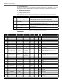
C - Supervision Status
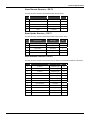
1 - SCAN_STATUS Parameter:
Status parameter of the scan done by the MB-700 in the communication with serial slave devices.
BIT
Message
0
Last write message Failed
1
Scan failed
2
Using configurable view
3
Scan Stopped
Description
When the value set for NUMBER_RETRANSMISSIONS is reached,
and if the MB-700 didn’t get to write data properly, the value
SCAN_STATUS will indicate “Last write message Failed”.
When the value set on NUMBER_RETRANSMISSIONS is reached
and the MB-700 didn’t get an answer from the serial slave, the value
of SCAN_STATUS will indicate “Scan Failed’.
If user set SCAN_BEHAVIOR equal to one and the communication
with the slave is done using View the scan status will indicate “Using
Configurable View”
Indicates if the scan stopped for any reason.
Table 4.2 – Description of the Status Bits
Parameters
Idx
Parameter
Data Type
(Length)
1
ST_REV
2
3
Default
Value
Unit
Store/
Mode
Unsigned16
0
None
S
TAG_DESC
OctString(32)
Spaces
Na
S
STRATEGY
Unsigned16
0
None
S
4
ALERT_KEY
Unsigned8
0
None
S
5
MODE_BLK
DS-69
O/S
Na
S
6
BLOCK_ERR
Bitstring(2)
E
D / RO
7
SLAVE_ADDRESS
Unsigned8
0 to 255
2
8
SERIAL_PORT
Unsigned8
1 : P1
2 : P2
1
1 to 255
Description
See Mode Parameter
S/
OOS
Address of slave device to be scanned.
1
S/
OOS
Serial port number where the slave device
is connected.
0
0
S/
OOS
Define if will use the configured view to
scan the device or not.
0
E
D / RO
Indicate the communication status with the
slave device.
9
SCAN_BEHAVIOR
Unsigned8
0 : Use Config
View
1 : Not Use
Config View
10
SCAN_STATUS
Bitstring(2)
See Scan_Status
bitstring
description
11
BVALUE
96 Boolean
FALSE
N
Boolean value scanned from slave device
12
IVALUE
8 Interge32
0
N
13
P_EU_VALUE_A
28 Float
0
N
14
P_EU_VALUE_B
28 Float
0
N
15
FVALUE
16 Float
0.0
N
Integer value scanned from slave device.
Percent to EU value scanned from slave
device
Percent to EU value scanned from slave
device
Float value scanned from slave device.
65535
S/
OOS
16
B_ADDRESS1
Unsigned16
…
…
…
111
B_ADDRESS96
Unsigned16
112
I_ADDRESS1
DS-264
…
…
…
119
4.8
Valid Range/
Options
I_ADDRESS8
DS-264
…
…
…
65535
…
…
…
…
Modbus address to locate boolean
variable
…
S/
OOS
Modbus address to locate boolean
variable
S/
OOS
Modbus address to locate integer variable
and length.
…
S/
OOS
…
Modbus address to locate integer variable
and length.
MB-700 Function Blocks
Idx
Parameter
Data Type
(Length)
Valid Range/
Options
Default
Value
120
P_EU_ADDRESS_A
1
DS-265
…
…
…
147
P_EU_ADDRESS_A
28
DS-265
S/
OOS
Information to locate percentage variable
as well scaling conversion.
148
P_EU_ADDRESS_B
1
DS-265
S/
OOS
Information to locate percentage variable
as well scaling conversion.
…
…
…
175
P_EU_ADDRESS_B
28
DS-265
176
F_ADDRESS1
Unsigned16
…
…
…
Unit
Store/
Mode
S/
OOS
…
…
…
…
…
…
65535
…
…
…
…
…
Information to locate percentage variable
as well scaling conversion.
…
…
S/
OOS
Information to locate percentage variable
as well scaling conversion.
S/
OOS
Modbus address to locate float variable
…
S/
OOS
65535
Description
191
F_ADDRESS16
Unsigned16
192
UPDATE_EVT
DS-73
Na
D
193
BLOCK_ALM
DS-72
Na
D
…
Modbus address to locate float variable
This alert is generated by any change to
the static data.
The block alarm is used for all
configuration, hardware, connection failure
or system problems in the block. The
cause of the alert is entered in the
subcode field. The first alert to become
active will set the Active status in the
Status attribute. As soon as the
Unreported status is cleared by the alert
reporting task, another block alert may be
reported without clearing the Active status,
if the subcode has changed.
Table 4.3 - Legend: Store / Mode Column – Store: data storage (D – Dynamic; S – Static; N – Non volatile) / Mode: minimal necessary mode
for user modify the parameter (OOS – Out of Service, MAN - Manual); If the mode column is empty indicates that the parameter does not
depends on the mode to be modified. RO – Read Only; Unit Column - E – Enumerated parameter; Na – Dimensionless Parameter.
4.9
MB-700 – User’s Manual
Block CCCM - Concentrate Control Master
Overview
The CCCM block supplies a way to change data between a Modbus slave device and another
Modbus slave device or Foundation Fieldbus Device to control process applications.
Schematic
Figure 4.5 – CCM Block Schematic
Description
The CCCM Block allows the change of data between RTU/TCP Modbus slave devices. As each
point is configured individually, it is not necessary that the devices are in the same network For
example, a slave must be connected in the serial port of the MB-700 and another might be
connected in the Ethernet network or even in another serial port of another MB-700. User needs
only to inform the Modbus address of each device, addresses of Modbus variables and a MB-700
internal “link” connecting the input parameter to the output parameters of the same CCCM block, so
that the MB-700 establishes “peer-to-peer” connection between two devices.
The block has status to each point indicating if the communication is ok, this status is provided in the
OUT_xx.Status and IN_xx.Status parameter.
The COMM_STATUS parameter is a bitstring with a summary of all good, bad or not configured
status of the block. If the bit is one indicates that the point is bad or not configured.
Optionally, a status parameter from variable of Modbus slave device can be configured for each
point
(this
status
is
associated
to
OUT_xx
IN_xx
parameter
through
TM
Fieldbus standard).
MODBUS_ADDRESS_OF_STATUS argument and uses FOUNDATION
Then, if it wished that an indication variable of internal status from Modbus slave device would be
transferred to other slave, it can be configured in this status.
NOTE
User must set the MODE_BLK parameter of the CCCM block to “auto”, so this block will work
properly. See description of this parameter in the previous item, CCSM block.
A - Functioning of a Communication “Peer-to-peer” in a MODBUS
Device
Block CCCM must be set to establish communication of data between two slaves through MB-700.
So user will have to connect the MODBUS addresses of the inputs and outputs.
4.10
MB-700 Function Blocks
Figure 4.6 - Functioning of a Communication “Peer-to-peer” in a MODBUS Device
A Peer-to-Peer example is showed in the Figure 4.6. Assume that wish read a variable from slave 1
and write in the slave 2. Each variable (of slave1 read and of slave2 write) have a Modbus address,
which must be obtained of the slave device (consult the manufacturer’s manual).
The first step would be identify which the address of the modbus slave devices, and identify the
variables which wishes read and write. The read variable (VAR_OUT_1) is associated to (OUT_xx)
CCCM block output. The write variable (VAR_IN_1) is associated to (IN_xx) CCCM block input.
After identify the variables, is necessary make a relationship between the input variable and the
output variable. There are two ways to do this relation:
• (*)Automatic – where each input and output already related, that is, OUT_1 linked with IN_1,
OUT_2 linked with IN_2, ..., OUT_D1 linked with IN_D1, OUT_D2 linked with IN_D2. To enable
this option set the parameter ALERT_KEY = 5. Any value in the ALERT_KEY parameter
different of 5, disable the option.
• By “Link” in the Strategy – in this case a link must be made between the wished input and
output. The Figure 4.7 shows this connection using “Link”.
Figure 4.7 – Peer-to peer Connection in the CCM Block
Where the relation option is through “Link”, see the following observations:
• To verify if the point is or no being read, must be observed the COMM_STATUS parameter,
because the status of the IN_xx parameter indicate the status of the OUT_xx variable which is linked
to it. For example, in the example above a status “good” in the IN_1 parameter indicate that the
value which is being read by OUT_1 parameter of the slave 1 is Ok, but it not indicate that the slave
2 is receiving the value. The read must be checked in the COMM_STATUS parameter.
• The block mode in Manual means that the inputs are being read but are not being repassed to
the block. The operator will able to modify the value of the OUT_xx variable, because this value will
be repassed for IN_x and for the slave device related to it.
(*) Where the option of relation is Automatic, have the following observations:
• In this option the Manual mode is not available.
4.11
MB-700 – User’s Manual
•
The output status (OUT_x) reflects if the point is reading or no, or corresponds to value of
status, if the MODBUS_ADDR_0F_STATUS was configured. The status of the (IN_x) input reflect if
the point was written or no. If will be configured MODBUS_ADDR_0F_STATUS it reflects the read
value of the OUT_x status correspondent.
• Case the point can not be read from OUT_x, it will continue being written from the last valid
command of IN_x.
• This relation is more fast than “Link” relation, because it update automatically the output
command as to receive the input command, while that the other must wait the block processing.
NOTE
(*) This option is available with the version of firmware 4.5.5 of the MB-700.
More details about how configure a “peer-to-peer” connection are introduced in the Chapter 5 of this
Manual.
B - Addressing
1. EU_ADDRESS_IN1 to EU_ADDRESS_IN4 Parameters:
In these parameters user must inform Modbus addresses and parameters of the slave that receives
the value of the analog variable, that is the slave where the value will be sent in the input parameter
of the CCCM block. User will have to inform the parameters that are showed below. For further
information about Scaling Conversion, refer to the Appendix C:
9
9
9
9
FROM_EU_100%
FROM_EU_0%
TO_EU_100%
TO_EU_0%
9 DATATYPE
The format for the data among the available types can be selected in this parameter. Refer to the
Appendix C for details about data types.
9 PORT_NUMBER
User must inform the MB-700 port to be used for communication between slaves: Ethernet, P1 or
P2.
9 SLAVE_ADDRESS
In this parameter, it must inform the Modbus address of the slave device.
9 MODBUS_ADDRESS_OF_VALUE
In this parameter, it must inform the Modbus address of the variable to be written whose value is “y”.
9 MODBUS_ADDRESS_OF_STATUS
In this parameter, it must inform the Modbus address of the variable to be written in the slave
device.
2. EU_ADDRESS_OUT1 to EU_ADDRESS_OUT4 Parameters:
In these parameters user will have to inform Modbus address and parameters of the slave that
informs the value of the analog variable, that is, the variable to be read.
User must inform the following parameters:
9
9
9
9
FROM_EU_100%
FROM_EU_0%
TO_EU_100%
TO_EU_0%
9 DATATYPE
The format for the data among the available types can be selected in this parameter. Refer to the
Appendix C for details about data types.
9 PORT_NUMBER:
User must inform the MB-700 port to be used for communication between slaves: Ethernet, P1 or
P2.
4.12
MB-700 Function Blocks
9 SLAVE_ADDRESS
In this parameter, it must inform the Modbus address of the slave device.
9 MODBUS_ADDRESS_OF_VALUE
In this parameter, it must inform the Modbus address of the variable read from slave.
9 MODBUS_ADDRESS_OF_STATUS
In this parameter, it must inform the address of status of the variable read from slave.
3. EU_ADDRESS_IN_D1 to EU_ADDRESS_IN_D2 Parameters:
In this parameters user will inform the Modbus addresses and parameters of the slave where the
boolean value will be written. User must inform the following parameters:
9 PORT_NUMBER
User must inform the MB-700 port to be used for communication between slaves: Ethernet, P1 or
P2.
9 SLAVE_ADDRESS
In this parameter, it must inform the Modbus address of the slave device.
9 MODBUS_ADDRESS_OF_VALUE
In this parameter, it must inform the Modbus address where the variable value will be written. Inform
the address of the Modbus variable of the slave device to be written whose value is the value of
input parameter IN_DX.
9 MODBUS_ADDRESS_OF_STATUS
In this parameter, it must inform the address of status of the variable read from slave.
4. EU_ADDRESS_OUT_D1 to EU_ADDRESS_OUT_D2 Parameters:
In these parameters user will inform Modbus addresses and parameters of the slave that informs
the value of the digital variable, that is., the variable to be read. User will have to inform the following
parameters.
9 PORT_NUMBER
User must inform the MB-700 port to be used for communication between slaves: Ethernet, P1 or
P2.
9 SLAVE_ADDRESS
In this parameter, it must inform the Modbus address of the slave device.
9 MODBUS_ADDRESS_OF_VALUE
In this parameter, it must inform the Modbus address of the variable read from slave that will be
available in the output parameter OUT_DX of this block.
9 MODBUS_ADDRESS_OF_STATUS
In this parameter, it must inform the address of status of the variable read from slave.
Sending the configuration to the MB-700
User must change the ON_APPLY parameter to “Apply” to update the new configuration made. To
do it, user must access the CCCF block and proceed as indicated.
IMPORTANT
If the user does not accomplish this procedure, the selected configuration will not be sent to the
MB-700. The configuration was updated after writing, but the block will execute again after
ON_APPLY having been put on “Apply”.
C - Monitoring Data
•
Analog input monitoring parameters of the CCCM Block: IN1, IN2, IN3, IN4.
•
Analog output monitoring parameters of the CCCM Block: OUT1, OUT2, OUT3, OUT 4.
•
Digital input monitoring parameters of the CCCM Block: IN_D1, IN_D 2, IN_D 3, IN_D 4.
•
Digital output monitoring parameters of the CCCM Block: OUT_D1, OUT _D2, OUT _D3,
OUT_D4.
4.13
MB-700 – User’s Manual
D - Supervision Status
1 - Parameter COMM_STATUS
This parameter indicates if the communication between slaves was established properly. If the
corresponding bit is in logic level 1, it means there was an error during writing/reading of the
respective parameter.
Bit
0
1
2
3
4
5
6
7
8
9
10
11
12
13
14
15
Variable
BAD COMM MOD_VAR_IN1
BAD COMM MOD_VAR_IN2
BAD COMM MOD_VAR_IN3
BAD COMM MOD_VAR_IN4
BAD COMM MOD_VAR_IN_D1
BAD COMM MOD_VAR_IN_D2
BAD COMM MOD_VAR_IN_D3
BAD COMM MOD_VAR_IN_D4
BAD COMM MOD_VAR_OUT1
BAD COMM MOD_VAR_OUT2
BAD COMM MOD_VAR_OUT3
BAD COMM MOD_VAR_OUT4
BAD COMM MOD_VAR_OUT_D1
BAD COMM MOD_VAR_OUT_D2
BAD COMM MOD_VAR_OUT_D3
BAD COMM MOD_VAR_OUT_D4
Table 4.4 – Bit / Parameter Status
Parameter Status
Each input or output parameter has a corresponding status. The slave device through configuration
of the MODBUS_ADDRESS_OF_STATUS might update this status. This happens only if the slave
TM
device has a status (this status follows the FOUNDATION Fieldbus standard). See more details of
how to set this status in the Function Blocks manual. If the MODBUS_ADDRESS_OF STATUS
parameter is not configured, the CCCM Block automatically updates the status to “Good Non
Cascade” when the communication with slave is OK or “Bad No Communication with last value” and
“Non-Specific”, if communication fails.
Parameters
Idx
Parameters
Data Type
(Length)
Valid
Range/
Options
Default
Value
Unit
Store /
Mode
None
S
1
ST_REV
Unsigned16
0
2
3
4
5
6
TAG_DESC
STRATEGY
ALERT_KEY
MODE_BLK
BLOCK_ERR
OctString(32)
Unsigned16
Unsigned8
DS-69
Bitstring(2)
Spaces
0
0
O/S
7
COMM_STATUS
Bitstring(2)
8
IN1
DS-65
9
EU_ADDRESS_IN1
DS-266
10
IN2
DS-65
11
EU_ADDRESS _IN2
DS-266
12
IN3
DS-65
4.14
1 to 255
0
Description
Na
S
None
S
None S / OOS
Na
S
See Mode Parameter
E
D / RO
Indicate if communication from slave is good or not
E
D / RO
(each bit corresponds to a Modbus variable).
N
Analog input 1
Information to generate constants A and B em
S / OOS equation Y=A*X+B plus the addresses in a slave
device.
N
Analog input 2
Information to generate constants A and B em
S / OOS equation Y=A*X+B plus the addresses in a slave
device.
N
Analog input 3
MB-700 Function Blocks
Valid
Range/
Options
Idx
Parameters
Data Type
(Length)
Default
Value
13
EU_ADDRESS _IN3
DS-266
14
IN4
DS-65
15
EU_ADDRESS _IN4
DS-266
16
17
18
19
IN_D1
ADDRESS _IN_D1
IN_D2
ADDRESS _IN_D2
DS-66
DS-267
DS-66
DS-267
Information to generate constants A and B em
S / OOS equation Y=A*X+B plus the addresses in a slave
device.
N
Analog input 4
Information to generate constants A and B em
S / OOS equation Y=A*X+B plus the addresses in a slave
device.
N
Discrete input 1
S / OOS Addresses in a slave device.
N
Discrete input 2
S / OOS Addresses in a slave device.
20
21
22
23
24
IN_D3
ADDRESS _IN_D3
IN_D4
ADDRESS _IN_D4
OUT1
DS-66
DS-267
DS-66
DS-267
DS-65
N
S / OOS
N
S / OOS
N / Man
25
EU_ADDRESS
_OUT1
DS-266
S / OOS
26
OUT2
DS-65
N / Man
27
EU_ADDRESS
_OUT2
DS-266
S / OOS
28
OUT3
DS-65
N / Man
29
EU_ADDRESS
_OUT3
DS-266
S / OOS
30
OUT4
DS-65
N / Man
31
EU_ADDRESS
_OUT4
DS-266
S / OOS
32
33
34
35
36
37
38
OUT_D1
ADDRESS _OUT_D1
OUT2_D2
ADDRESS _OUT_D2
OUT_D3
ADDRESS _OUT_D3
OUT_D4
DS-66
DS-267
DS-66
DS-267
DS-66
DS-267
DS-66
N / Man
S / OOS
N / Man
S / OOS
N / Man
S / OOS
N / Man
39
ADDRESS _OUT_D4
DS-267
40
UPDATE_EVT
DS-73
Na
41
BLOCK_ALM
DS-72
Na
Unit
Store /
Mode
Description
Discrete input 3
Addresses in a slave device.
Discrete input 4
Addresses in a slave device.
Analog output 1
Information to generate constants A and B em
equation Y=A*X+B plus the addresses in a slave
device.
Analog output 2
Information to generate constants A and B em
equation Y=A*X+B plus the addresses in a slave
device.
Analog output 3
Information to generate constants A and B em
equation Y=A*X+B plus the addresses in a slave
device.
Analog output 4
Information to generate constants A and B em
equation Y=A*X+B plus the addresses in a slave
device.
Discrete output 1
Addresses in a slave device.
Discrete output 2
Addresses in a slave device.
Discrete output 3
Addresses in a slave device.
Discrete output 4
S / OOS Addresses in a slave device.
This alert is generated by any change to the static
D
data.
The block alarm is used for all configuration,
hardware, and connection failure or system
problems in the block. The cause of the alert is
entered in the subcode field. The first alert to
D
become active will set the Active status in the Status
attribute. As soon as the Unreported status is
cleared by the alert reporting task, another block
alert may be reported without clearing the Active
status, if the subcode has changed.
Table 4.5 - Legend: Store / Mode Column – Store: data storage (D – Dynamic; S – Static; N – Non volatile) / Mode: minimal necessary mode
for user modify the parameter (OOS – Out of Service, MAN - Manual); If the mode column is empty indicates that the parameter does not
depends on the mode to be modified. RO – Read Only; Unit Column - E – Enumerated parameter; Na – Dimensionless Parameter.
4.15
MB-700 – User’s Manual
Block CCDL – Concentrate Data Logger
Overview
This block supplies a mechanism to search data stored in Modbus slave devices in an optimized
way. A Modbus variable specified in the configuration will be used to indicate whether it is necessary
to scan stored data whose Modbus address are entered by user.
Description
It is an optimized mechanism to bring data stored from the LC700.
• To start the FIFO Data Logger block of the LC700 when the communication with a MB-700
master (for example a HMI) fails, the CCDL block sends a Modbus command to the variable in the
LC700 pointed by STOP_SCAN_ADDRESS. The block writes TRUE in the variable when it is
necessary to enable and FALSE when it is required to disable the FIFO data logger.
• If data supervision is normal (for example, if a HMI system communicates normally with a
supervision Block-CCSM) in the scan of the CCDL Block, it will monitor the Modbus variable
pointed by NEED_SCAN_ADDRESS to know if there is any data in the Data Logger. If the variable
is not zero it indicates that there’s data in the Data Logger. Parameter LOGGER_ADDRESS points
to an address of beginning of the data logger block (FIFO.CTW). The parameter NUM_REGISTER
shows the amount of registers stored on the CCDL Block.
1 – Parameter TYPE_OF_LOG
It sets the time_stamp of the data logger.
2 – Parameter P_EU_ADDRESS_A1
It sets the conversion scale and the data format of the FIFO Block data logger (these parameters
must have the same configuration of the respective FIFO data logger in the LC700). For further
information about Scale Conversion, refer to the Appendix C. User will have to set the following
parameters:
9
9
9
9
FROM_EU_100%
FROM_EU_0%
TO_EU_100%
To_EU_0%
9 DATATYPE
Choose the format of data read from the device. Data types supported by the data logger (they will
be converted to float) are: float and Integer16.
9 MODBUS_ADDRESS_VALUE
Not used.
•
4.16
Blocks in Cascade - The CCDL block can store up to 280 registers. If the CCDL block is not
enough to store all data stored in the FIFO, it is possible to put blocks in cascade as many
times as necessary and set all of them with the same information (MODE_BLK,
SLAVE_ADDRESS, NEED_SCAN_ADDRESS, LOGGER_ADDRESS, etc). So when the data
logged brought from the FIFO block do not fit in the CCDL and there is another CCDL block set
for that FIFO, this block will receive the rest of the data log. The CCDL block indicates in the
parameter NEXT_BLOCK_LOG which is the next block containing the rest of the data logged.
MB-700 Function Blocks
Parameters
Idx
Parameter
Data Type/
Length
1
2
3
ST_REV
TAG_DESC
STRATEGY
Unsigned16
OctString(32)
Unsigned16
4
ALERT_KEY
Unsigned8
5
6
MODE_BLK
BLOCK_ERR
DS-69
Bitstring(2)
7
SLAVE_ADDRESS
Unsigned8
8
SERIAL_PORT
Unsigned8
9
SCAN_STATUS
Bitstring(2)
10
NEED_SCAN_ADDRESS
Unsigned16
11
CLEAR_LOG_ADDRESS
Unsigned16
12
NEED_SCAN_COUNTER
Unsigned16
13
TYPE_OF_LOG
Unsigned8
14
P_EU_ADDRESS_A1
DS-265
15
LOGGER_ADDRESS
Unsigned16
0
E
16
NUM_REGISTER
Unsigned16
0
E
17
STOP_SCAN_ADDRESS
Unsigned16
0 - 9999
0
E
18
NEXT_BLOCK_LOG
Visiblestring(32)
19
…
28
LOG_FVALUE_1
…
LOG_FVALUE_10
28 Float
...
28 Float
...
0.0
...
0.0
...
29
TIME_STAMP_1
28 Time Value
...
...
...
Valid Range/
Options
1 to 255
0 to 255
1 : P1
2 : P2
See the Scan
Status
Default
Value
Unit
Store /
Mode
0
Spaces
0
None
Na
None
S
S
S
0
None
S
O/S
Na
E
S
D / RO
S/
OOS
S/
OOS
2
1
1
0
E
1-49999
0
E
1-9999
0
E
0
E
0
E
0:Only last time
stamp
1:Every sample
2:No time stamp
Description
See Mode Parameter
Address of slave device to be scanned.
Serial port number where the slave
device is connected.
Indicate the communication status with
D/RO
the slave device.
This is the Modbus address of a flag
S/
that indicates if it is necessary to scan
OOS
the logged data.
Address of variable in the Slave
Modbus Device to clear the data logger.
S/
It can be used to clear data logger after
OOS
reading it. If the address is the default
(0), then this mechanism is disabled.
It indicates the number of scans for the
logged data. This variable may be used
D / RO by the OPC Server to trigger a scan
command to red LOG_FVALUEx and
TIME_STAMP_x.
S/
OOS
Selection of log type.
Information
to
locate
percentage/FLOAT variable as well
scaling conversion.
S/
Modbus address of data logger
OOS beginning
D / RO Number of logged FIFO registers
MB-700 may force the trigger of data
S
logger writing TRUE to a Modbus
variable in the slave Modbus device.
Block tag of next CCDL block
S
associated to this data logger.
N/RO Float value scanned from slave device.
...
…
N/RO Float value scanned from slave device.
Time
stamp
of
samples
in
N/RO
LOG_FVALUE1
...
…
Time
stamp
of
samples
in
N/RO
LOG_FVALUE10
This alert is generated by any change
D
to the static data.
The block alarm is used for all
configuration, hardware, connection
failure or system problems in the block.
The cause of the alert is entered in the
subcode field. The first alert to become
active will set the Active status in the
D
Status attribute. As soon as the
Unreported status is cleared by the
alert reporting task, another block alert
may be reported without clearing the
Active status, if the subcode has
changed.
S/
OOS
…
…
...
38
TIME_STAMP_10
28 Time Value
39
UPDATE_EVT
DS-73
Na
40
BLOCK_ALM
DS-72
Na
Table 4.6 - Legend: Store / Mode Column – Store: data storage (D – Dynamic; S – Static; N – Non volatile) / Mode: minimal necessary mode
for user modify the parameter (OOS – Out of Service, MAN - Manual); If the mode column is empty indicates that the parameter does not
depends on the mode to be modified. RO – Read Only; Unit Column - E – Enumerated parameter; Na – Dimensionless Parameter.
4.17
MB-700 – User’s Manual
4.18
Chapter 5
ADDING MODBUS TO THE MB-700
MB-700 as Serial MODBUS Master
Scenario
Figure 5.1 – MB-700 Architecture Example as a Serial MODBUS Master
Description
In this scenario the MB-700 has the following roles simultaneously, when the Bypass Direction
parameter is set for “TCP to Serial”.
¾
Bypass (TCP/IP to serial): The MB-700 passes the MODBUS message transmitting it to a lower
level of the network. The MB-700 acts as TCP/IP Modbus to serial Modbus RTU (485 ou 232)
converter.
¾
Concentrator: Modbus variables of the devices are read processed (Data Type conversion and
scale) and stored in parameters of the CCSM block. So instead of the HMI communicating
directly with the slave devices it will communicate directly with the MB-700 only.
¾
Peer-to-peer: Two Modbus slaves change data between each other. Peer-to-peer function
allows it. Slaves might be in different Modbus networks and even they can change data
between each other.
The system above is indicated for remote control operations, where the process is located in a not
easily accessible area, a place too far from the supervision system. User does not need to go to the
area, it is only necessary that he is connected to the Ethernet network.
The MB-700 has two serial ports EIA-232 and EIA-485 allowing connection with logic controllers
through a MODBUS network or through a MODEM. Using the EIA-485 port it is possible to create a
multi drop network with logic controllers or to integrate an already existent network. For remote
control, in distant locations, a modem or radio might be used in the EIA-232 port to establish
communication between the system HMI and configuration systems with controllers in the process
plant.
5.1
MB-700 – User’s Manual
In this application the MB-700 has two basic functions: MODBUS Bypass and Data Concentrator.
The Modbus Bypass happen when a MODBUS data reaches the MB-700, that is., CONF700 (or any
other Modbus configuration system) sends commands to set any slave device in the Modbus sub
net. In this case the MB-700 ignores the message and passes it to the target slave. MB-700 also
has the functionality of concentrator of data.
Instead of the supervision system accessing a field device in particular, it just searches for data
monitored in MB-700 memory. Data collected are sent within a determinate time base to the MB-700
and the supervision system looks for these data directly in the MB-700 memory increasing speed of
access because the HMI does not need to access the field device directly.
The MB-700 is set through Syscon. Fieldbus Foundation Blocks CCCF and CCSM set the
concentrator function of the MB-700 and the CCCM Block sets the peer-to-peer communication. The
MB-700 has an IP within an Ethernet used for communication between the operation system and
the MB-700. Each slave of the network has a MODBUS address that must be informed to the
SYSCON. Each I/O and the respective addresses must also be informed to the SYSCON. In the
above configuration the peer-to-peer may for example be easily implemented.
OFF LINE Configuration
IMPORTANT
Before the user starts configuring the MB-700, it is necessary read first Chapter 4 of this manual.
A - Configuring the IP of the MB-700
Set the IP of the MB-700 connecting it to the subnet, for more details about how to configure the IP
address, refer to the chapter 2 “ Connecting the MB-700 to the Subnet”.
B - Initializing the SYSCON
•
Add the MB-700 to the Syscon. Start SYSCON.
•
Click at Project ÆNew Æ Project. After, click at Fieldbus Networks Æ New Fieldbus.
• Select Expand to open an auxiliar window. In this new window, right-click in NewÆBridge. Select
the manufacturer "Smar", and them the device "MB-700";
•
Save it.
For further details, see SYSCON Manual and the Chapter 3 of this Manual.
IMPORTANT
The user must be sure that Smar.DFIOLEServer.0 is set in the Communication Settings menu.
Otherwise it won’t get to communicate the MB-700 and SYSCON.
In the item below, the necessary minimum configuration is explained for the MB-700 acts as
“Bypass”, “Concentrator” and “Peer-to-peer”.
C - Configuring Blocks
1) MB-700 working as Bypass
In order to the MB-700 works as Bypass, it is necessary to configure just the Resource and CCCF
Blocks.
RESOURCE block
Steps to configure the Resource Block:
•
The only necessary parameter to be set here is MODE_BLK. Be sure that
MODE_BLK.TARGET = “Auto”.
•
5.2
Right click the <VB_VFD> icon. A new window will open. Select the New Block option.
Adding Modbus to the MB-700
•
•
A window will appear. Select RESOURCE Block and give a name to it. Right click the block
created and then select Off Line Characterization.
Find the parameter MODE_BLK.TARGET and put it in “Auto”.
Figure 5.2 - Syscon Screens
Figure 5.3 - Adding Block
CCCF Block
Steps to configure the CCCF Block:
•
In the SYSCON find the MB-700.
•
Right click <VB_VFD> icon. A new window will appear. Select the New Block option.
•
A window will appear. Select the CCCF Block, give a name to it and click the OK button to
conclude this task. Right click the block and next select Off Line Characterization.
5.3
MB-700 – User’s Manual
Figure 5.4 – Configuration Screen CCCF Block
The following parameters must be adjusted:
9 BAUD_RATE: Adjust to 57600.
9 BYPASS_DIRECTION: TCP to Serial.
9 NUMBER_RETRANSMISSIONS: Choose "3".
9 TIMEOUT: "1000" (1000 ms).
9 MODE_BLK: Select "Auto".
9 DEVICE_ADDRESS: Make sure that in the MODBUS network there is not any other address
with the number shown for this parameter. Default: 247.
9 ON_APPLY: Set this parameter for “Apply”.
To have best visualization, rename the blocks which have created. Right click the Block 1(where a
RESOURCE block must have added). A menu will open.
•
User should select the Attributes option and change the block tag according to the
convenience. The same procedure might be done with the other blocks.
•
At the end, a table like below must appear on Syscon.
5.4
Adding Modbus to the MB-700
Figure 5.5 – MB-700 Blocks Configuration Example
2) MB-700 working as Concentrator
For the MB-700 works as Concentrator, it is necessary to configure, besides the previous blocks,
the CCSM Block.
CCSM Block
Steps to configure the CCSM Block:
NOTE
The MODBUS addresses shown have the following addressing:
9 0001 to 9999 Î Digital Outputs
9 10001 to 19999 Î Digital Inputs
9 30001 to 39999 Î Analog inputs
9 40001 to 49999 Î Analog outputs
In a few moments user will have to inform to the SYSCON MODBUS addresses of the devices. In
case of data in the integer format with 4 bytes and float user will always note ONLY the first
address, once these data types use 2 positions.
• On the SYSCON find the MB-700.
• Right click the <VB_VFD> icon. A window will appear. Select the New Block option.
• Next select CCSM block. Right click the block just created, and next select Off Line
Characterization.
• Set MODE_BLK.TARGET= “Auto”.
• The parameter SLAVE_ADDR must have the address of the LC700 target, in this case LC700 1
or the Modbus address of the slave. For this case, the address is 1.
• SERIAL_PORT will be set for P1 to communicate through ports EIA-232 and EIA-485.
NOTE
If user is using Smar Modbus Slave Devices will be able to change the parameter
SCAN_BEHAVIOR to “Using Config View” and this way will enable a much faster
communication between MB-700 and slave devices.
In the proposed scenario in the Figure 5.1, the LC700 1 has one I/O card connected to eight
discrete switches, eight digital outputs represented by LEDs and two inputs for the two transmitters.
Consider that the LC700 has address 1 within that network and it is required to set points of the
Table 5.1. Note that the MODBUS addresses of the input variables to be monitored must be also
informed.
5.5
MB-700 – User’s Manual
Input/Output
LED 1
LED 2
LED 3
LED 4
LED 5
Digital
Digital
Digital
Digital
Digital
Data Type
00001
00002
00003
00004
00005
Modbus Adresses
LED 6
LED 7
LED 8
Switch 1
Switch 2
Switch 3
Switch 4
Switch 5
Switch 6
Switch 7
Digital
Digital
Digital
Digital
Digital
Digital
Digital
Digital
Digital
Digital
00006
00007
00008
10001
10002
10003
10004
10005
10006
10007
Switch 8
Transmitter 1
Transmitter 2
Digital
Percentage
Percentage
10008
30001-30002
30003-30004
Table 5.1 – Modbus Points Configuration Example from Modbus Slave
•
•
In the SYSCON right click the block just created named CCSM.
Select the Off Line Characterization option.
In this window user will find the parameters B_ADDRESS1 to B_ADDRESS96.
• Click the B_ADDRESS1 parameter and type in the blank field the corresponding MODBUS
address, that is, 10001.
• Next click the End Edit button.
• Repeat the same procedure for B_ADDRESS2 to B_ADDRESS8 adding MODBUS addresses to
the ON/OFF switches according to the Table 5.1.
Figure 5.6 - Setting the CCSM Block (1)
5.6
Adding Modbus to the MB-700
The user should set the transmitter inputs. In the window above search for the parameters
P_EU_ADDRESS_A1 to P_EU_ADDRESS_A28. Click the P_EU_ADDRESS_A1 parameter. User
will set the following parameters:
Ö FROM_EU_100%
Inform the maximum value to the input variable read in the transmitter 1.
Ö FROM_EU_0%
Inform the minimum value of the variable read in the transmitter 1.
Ö TO_EU_100%
Inform the maximum value of the parameter P_EU_VALUE_A[0].
Ö TO_EU_0%
Inform the minimum value of the parameter P_EU_VALUE_A[0].
Ö DATATYPE.
Choose the format to the Modbus variable read from the slave device. For further details about the
available data types, refer to the table in the Appendix C.
Ö MODBUS_ADDRESS_OF_VALUE.
Type the address 30001, where it is connected the value read from transmitter 1. According to the
type of data used in the variable reading the transmitter will use one or two addresses. Only the first
address will be informed.
Figure 5.7 - Setting the CCSM Block (2)
After finishing this configuration the user must have a window similar to (see figure 5.8):
5.7
MB-700 – User’s Manual
Figure 5.8 - Block Configuration Finished
3) MB-700 working as Peer-to-peer
For the MB-700 works as Peer-to-peer between Modbus devices in the same serial network, it is
necessary to configure, besides the Resource and CCCF Blocks, the CCCM Block.
CCCM Block
To configure the CCCM block, follow the steps below.
Figure 5.9 - Adding the CCCM Block
After inserting this block, the Fieldbus window should be similar to:
5.8
Adding Modbus to the MB-700
Figure 5.10 - CCCM Block Added into the Project
Change MODE_BLK to “Auto”.
Initially the modbus variables of the slaves which is desirable read and write values will be
associates. For example, considering the example of Figure 5.1 where Modbus slaves devices are
in MB-700 serial port and is desirable transfer a variable of a slave 1 to slave 2. Then, the reading
variables in OUT_xx parameters and the write variables in IN_xx parameter of the CCCM block are
associates.
Find EU_ADDRESS_OUT1. Click this parameter and configure:
Ö FROM_EU_100%
Inform the maximum value of input variable read from the LC700 Function Block.
Ö FROM_EU_0%
Inform the minimum value of the Modbus variable read from the LC700 system.
Ö TO_EU_100%
Inform the maximum value of the variable to be monitored.
Ö TO_EU_0%
Inform the minimum value of the variable to be monitored.
Ö DATATYPE
Choose the format for the data. For further details about the available data types, refer to the table
in the Appendix C.
Ö PORT_NUMBER
Set the port P1. P1 is selected because the communication is done through the serial ports of the
MB-700.
Ö SLAVE_ADDRESS
Insert the number of MODBUS slave.
Ö MODBUS_ADDRESS_OF_VALUE
Insert the MODBUS address of the slave 1 reading variable.
5.9
MB-700 – User’s Manual
Figure 5.11 - Setting the CCCM Block
To configure the reading variables, find the parameter EU_ADDRESS_IN1. Inform the required
parameters. They are similar to the parameters EU_ADDRESS_OUT1 of the CCSM block. However
SLAVE_ADDRESS must be equal to the value of the address of the second slave of the MOBDUS
network.
In the parameter MODBUS_ADDRESS_OF_VALUE, insert the MODBUS address of write variable
of the slave 2.
Is necessary relate the input and output variables to indicate where is the points of reading and
where is the write points of the do “Peer-to-peer”. Case the user wish the relation by “link” must
proceed as:
Configure the CCCM in the logic diagram.
• In the SYSCON, right click Area1 icon.
• Select New Process Cell option.
• In Process Cell 1 right click the Expand option.
• In the new window, right click Process Cell1 and select New Control Module.
• In Control Module 1, right click it and select Strategy. At the end, user will have 4 windows
opened:
9
9
9
9
One main window with the name of the file
A Process Cell window
A Fieldbus Window
A Control Module Window
• In the Fieldbus window drag the CCCM icon to the Control Module window. SYSCON will insert
the CCCM Block in this window.
• Click the link button.
• Right click the CCCM block in the Control Module window.
• Select OUT_1. Make a link to the input IN_1 of this same block. SYSCON will make the link the
between slaves.
5.10
Adding Modbus to the MB-700
Figure 5.12 – Configuration Example of a OUT_1 Link to IN_1 (Modbus Point to Point
Communication)
D - Configuration Download
Before starting the communication, the user must do the following procedure:
• In the main window, right click the first item of this window. In the current example the project
was called MB-700.
• Select Export tags. A window will open like below asking where the file with the tags will be
saved.
• Click the Save button.
Figure 5.13 - Choosing the Folder for Export Tags
Start the communication with the MB-700 by clicking in the On Line button.
5.11
MB-700 – User’s Manual
• In case the communication is not established, right click Bridge icon and select Attributes.
• In the field Device ID, check if the device is recognized. Select the corresponding number of the
device. See the serial number in the identification label of the MB-700 module.
• Next download the configuration. Right click the Fieldbus1 or Bridge (MB-700) and select
Download. The configuration will be sent to the MB-700.
• After having sent the configuration, user must change the parameter ON_APPLY of the CCCF
Block to “Apply”. This will update the configuration of the CCSM Block.
On Line Configuration
It is possible to set blocks of the MB-700 on line with the device connected to the network and
functioning. It is only necessary that user right-clicks the block and select On Line Characterization.
User may also monitor all parameters now.
IMPORTANT
To make effective the new configuration, user must always change the parameter ON_APPLY to
Apply, otherwise this configuration will not be updated in the MB-700. User also must check which
parameters may be set and changed in the “Auto” mode because a few parameters may only be
changed in the OOS mode.
MB-700 as a TCP/IP Master
Description
MB-700 functionality in this scenario:
¾ Bypass (Serial to TCP): MB-700 works as protocol converter. In this function it converts a serial
MODBUS RTU message to TCP/IP and TCP/IP to Modbus RTU.
¾ Peer-to-peer: MB-700 can exchange data between slave Modbus devices. These slave devices
might be in different Modbus networks and even they can change data between each other.
1 - MB-700 working as Bypass (Serial to TCP)
In this scenario MB-700 does not have concentrator functionality. Thus the only two Blocks required
to be set are CCCF and RESOURCE. Several MB-700s are connected in an Ethernet. In every MB700 are connected several slave devices. User may set any of these controllers from the same
station. Two MB-700 are connected and the respective stations are connected through the serial
EIA-232 ports of each MB-700. The Ethernet ports connect these MB-700s to the corporate
network. Connected to this network is a third MB-700 and on it are connected the slave MODBUS
devices. MB-700 acts as a TCP/IP master establishing a bridge between workstations, local network
and MODBUS network. The great advantage given by this configuration is to allow the connection of
a MODBUS slave with several serial masters. This allows one slave to be accessible in several
points of Ethernet through MB-700.
NOTE
For this scenario, MB-700 does not support CCSM and CCCM Blocks.
5.12
Adding Modbus to the MB-700
Figure 5.14 – Example of MB-700 Architecture working as Serial Bypass for TCP
Configuration
The RESOURCE Block must have its parameter MODE_BLK put in “auto”.
The procedures to configure the CCCF Block are similar to the previous application, except by the
BYPASS_DIRECTION parameter now selected to “Serial to TCP”.
5.13
MB-700 – User’s Manual
Figure 5.15 - Setting the BYPASS_DIRECTION Parameter in the CCCF Block
The configuration of the Modbus Slaves in the CCCF Block follows the steps below:
•
If the configuration has only one a Modbus slave for a determined IP address, the
parameter SLAVE_ADDRESSES must be used. In this case, for each IP_SLAVE it has a
corresponding MODBUS_ADDRESS_SLAVE.
Figure 5.16 - Setting the Modbus Slaves in the CCCF Block
5.14
Adding Modbus to the MB-700
•
If the configuration has more than one Modbus slave for the same IP address, the
IP_SLAVE_x and DEVICE_IDS_IP_x parameters can be used. In this case, for each
IP_SLAVE it can configure up to 32 Modbus slave addresses.
Figure 5.17 - Setting the Modbus Slave IPs in the CCCF Block
In the CCCF Block, change the ON_APPLY parameter to “Apply”.
Click the ON button to start communication.
Next download the configuration. After this step, the communication is established and the MB-700
is On Line.
2 - MB-700 working as Peer-to-peer
For the MB-700 works as Peer-to-peer in the TCP/IP, the user must follow the defined steps for the
Off Line Configuration in the item MB-700 working as Serial Peer-to-peer, and, besides this, the
following parameters must be configured:
- In the CCCF Block, the SLAVE_ADDRESSES and/or IP_SLAVE parameter must be configured
with the IP and the Modbus address of the TCP/IP slaves (as described previously) up to the limit of
12 TCP/IP addresses.
- In the CCCM Block, the EU_ADDRESS_XXXX.PORT_NUMBER parameter, select “Ethernet”
indicating for this point (XXXX) the communication will be done through the TCP/IP. (Where XXXX
can be IN_1….IN_4, IN_D1…IN_D4, OUT_1…OUT_4, OUT_D1…OUT_D4).
5.15
MB-700 – User’s Manual
Figure 5.18 - MB-700 working as Peer-To-Peer in the Serial and TCP/IP
MB-700 as a TCP/IP Modbus Slave
1 - MB-700 working as Concentrator
The MB-700 module would operate as a Serial/TCP Modbus concentrator and can also work as
TCP Slave of the Concentrated Dynamic Data into its CCSM Block.
The Device Slave Address (ID Modbus) is defined in the DEVICE_ADDRESS parameter of the
Concentrate Configuration Block (CCCF).
The Modbus address of the parameter to be monitored is fixed for each CCSM Block and depends
on the block instantiation (it is indicated in the STRATEGY parameter).
To provide the redundancy, the MB-700 Blocks must answer like Slave Modbus as Active and also
as Standby.
Modbus Address Calculation
Each block has a fixed range of Modbus Addresses, which is defined following the form:
Modbus_Addr = Modbus_start_addr + (offset * n)
Where:
n –STRATEGY parameter of the CCSM block (indicate the block instantiation)
For the following configuration:
o MB-700
o CCSM1
o CCSM2
o CCSM3
o CCSM4
The Modbus Address of the BVALUE[1] parameter of the CCSM4 block would be:
Modbus_start_addr – BVALUE[1] = 1001
CCSM block Offset = 200
CCSM.Strategy = 3 (fourth SM block in the configuration)
Modbus_Addr = 1001 + (200 * 3)
Modbus_Addr = 1601
5.16
Adding Modbus to the MB-700
CCSM Block
Modbus Address
Index
Modbus Address
Modbus Address
Modbus Address
Strategy= 0
Offset_sm = 0
Strategy= 1
Offset_Sm = 200
Strategy = 2
Offset_Sm = 400
Parameter
DataType
10
SCAN_STATUS
UInteger16
42001 + Offset_SM
42001
42201
42401
11.1
BVALUE[1]
Bool
2001 + Offset_SM
2001
2201
2401
11.2
BVALUE[2]
Bool
2002 + Offset_SM
2002
2202
2402
11.96
BVALUE[96]
Bool
2096 + Offset_SM
2096
2296
2496
12.1
IVALUE[1]
Integer32
42002-42003 +
Offset_SM
42002-42003
42202-42203
42402-42403
12.2
IVALUE[2]
Integer32
42004-42005 +
Offset_SM
42004-42005
42204-42205
42404-42405
12.8
IVALUE[8]
Integer32
42016-42017 +
Offset_SM
42016-42017
42216-42217
42416-42417
13.1
P_EU_VALUE_A[1]
Float
42018-42019 +
Offset_SM
42018-42019
42218-42219
42418-42419
13.2
P_EU_VALUE_A[2]
Float
42020-42021 +
Offset_SM
42020-42021
42220-42221
42420-42421
13.28
P_EU_VALUE_A[28]
Float
42072-42073 +
Offset_SM
42072-42073
42272-42273
42472-42473
14.1
P_EU_VALUE_B[1]
Float
42074-42075 +
Offset_SM
42074-42075
42274-42275
42474-42475
14.2
P_EU_VALUE_B[2]
Float
42076-42077 +
Offset_SM
42076-42077
42276-42277
42476-42477
14.28
P_EU_VALUE_B[28]
Float
42128-42129 +
Offset_SM
42128-42129
42328-42329
42528-42529
15.1
FVALUE[1]
Float
42130-42131 +
Offset_SM
42130-42131
42330-42331
42530-42531
15.2
FVALUE[2]
Float
42132-42133 +
Offset_SM
42132-42133
42332-42333
42532-42533
15.16
FVALUE[16]
Float
42160-42161 +
Offset_SM
42160-42161
42360-42361
42560-42161
(Strategy = x)
Offset_SM = 200 * x
x = 0 ~ 24
Table 5.2 – Modbus Address Table of the MB-700 working as Modbus Slave
Using the Data Logger
Description
The MB-700 may store data Logs from a LC700 Data Logger Block (FIFO). So, during normal
reading of the Concentrate Data Logger it checks if there are data stored in the correspondent slave.
In case there are data stored it will read these data and clear the log buffer of the slave.
Configuration
First create a FIFO Block in the LC700. In the SYSCON configuration it is possible to include as
many Concentrate Data Logger Blocks as it is required. To insert a CCDL Block just proceed like it
was done to the other MB-700 Blocks.
NOTE: the amount of CCDL blocks depends on the FIFO size defined in the LC700 (FIFO Size).
Each CCDL supports up to 280 data samples. For example, if the FIFO size is 1000 registers and
the data type is integer (percentage) so it is necessary: 1000/280 = 4 CCDL blocks.
5.17
MB-700 – User’s Manual
In case the data type is REAL, using the same 1000 registers and knowing that one REAL value
requires 2 registers for each sample so the calculation becomes: 500/280 = 2 CCDL blocks. The
CCDL Block works together with the supervision blocks. Thus there must be supervision blocks
pointing to the same address of the slave so that the CCDL Block works properly.
An example of configuration is shown below. Consider a configuration where the LC700 has the
following settings:
•
•
•
•
•
•
SLAVE_ADDR = 1 (LC700 Address)
STOP_SCAN_ADDRESS = 2009 ( FIFO_LOAD )
CLEAR_LOG_ADDRESS = 2011 (FIFO_CLEAR)
LOGGER_ADDRESS = 42506 (FIFO_CTW)
NEED_SCAN_ADDRESS = 2 (FIFO_EMPTY)
DATATYPE BLOCO FIFO = REAL
Figure 5.19 - Setting the CCDL Block
5.18
Adding Modbus to the MB-700
FIFO1.CTW
FIFO1.SIZE
FIFO1.TRIGGER
:
42506
42507
42508
:
Modbus Address
FIFO_EMPTY = 0002
Modbus Address
FIFO_LOAD = 2009
Modbus Address
FIFO_CLEAR = 2011
Figure 5.20 – CCDL of the MB-700 Interaction with LC700
Putting CCDL Blocks in Cascade
In case the amount of stored data is bigger than it is supported by the CCDL block user might put
CCDL blocks in cascade, it is only necessary to repeat the same configuration to all the data logger
blocks. In this way, the MB-700 will start to use blocks according to the order of instantiation
indicating which is the next block stored through the parameter NEXT_BLOCK_LOG.
5.19
MB-700 – User’s Manual
5.20
Chapter 6
SCENARIOS
The following scenarios presented here use the Smar’s LC700 as an example of MODUS RTU
slave device, however, the MB-700 may be used with any MODBUS RTU slave device.
Multiple Masters TCP/IP Communicating Directly with Several LC700s,
including via Radio
Figure 6.1 – MB-700 Application Example as MODBUS Gateway (Serial Master)
In this application, the MB-700 supports the following simultaneous functionality:
9
9
9
CONF700 downloads/uploads via TCP/IP including remotely
Supervision of the LC700 via OPC and/or Modbus TCP/IP driver
Firmware download of the LC700 via TCP/IP including remotely
The MB-700 is connected to the corporate network through its Ethernet port. In the network is
connected the workstation to configure and monitor the slave devices. Serial ports EIA-232 and EIA485 allow 3 LC700 to be connected to the MB-700. Two of the controllers are connected through the
EIA-485 bus and a third one is connected through a radio link. This last one is a remote unit
because its physical location is far from the MB-700 master. The first LC700 has Modbus ID=2 and
the second ID= 4 and the remote LC700 has ID= 5.
The MB-700 has an IP address within the Ethernet. So the configuration and supervision tools might
“see” the MB-700 in this network. In the CCCF block communication parameters are set, like
TIMEOUT,
BAUDRATE,
BYPASS_DIRECTION
(TCP
to
Serial),
PARITY
and
NUMBER_RETRANSMISSIONS.
6.1
MB-700- User’s Manual
Multiple Masters TCP/IP Communicating Directly with several LC700s and
“Peer-to-peer” between LC700s within a same Modbus RTU Network
Figure 6.2 – MB-700 Application Example as MODBUS Gateway and Link of Point to Point Equipments (Serial Master)
In this application, the MB-700 supports the following simultaneous functionality:
9
9
9
9
CONF700 downloads/uploads via TCP/IP including remotely
Supervision of the LC700 via OPC and/or driver Modbus TCP/IP
Firmware download of the LC700 via TCP/IP including remotely
“Peer-to-peer” communication between LC700s within a same Modbus RTU network, including
remote units (From LC700 ID=2 to the LC700 ID= 5)
This scenario is similar to the previous one, however the peer-to-peer function was implemented.
There is peer-to-peer communication between LC700s of the same network, including remote units.
For example, from LC700 (ID=2) to LC700 (ID=5).
This functionality is added through the CCCM Block. In this block the parameter PORT_NUMBER is
set. Communication between slaves is made through the serial ports EIA-232 and EIA-485 (port P1
of the MB-700)
Communication Peer-to-peer between LC700s with MODBUS IDs 2 and 5, respectively, requires a
CCCM Block. This block will inform the MODBUS address of the variables that must be read and
the addresses where these variables will be written. Communication is made within the MODBUS
RTU network in an EIA-232 and EIA-485 (radio link) serial physical means.
Thus, the slave devices may change data directly from each other, without the message passing
through the TCP/IP masters. The MB-700 allows it connecting two points of the MODBUS network.
Within each CCCM Block up to 8 peer-to-peer links may be established, because it has 4 digital
inputs/outputs and 4 analog inputs/outputs.
6.2
Scenarios
Multiple Masters TCP/IP Communicating Directly with several LC700s and
“Peer-to-peer” between LC700’s of different Modbus RTU Networks
Figure 6.3 – MB-700 Application Example Link Point to Point Equipments Local and Remote (through TCP) and
Modbus Gateway
In this application, the MB-700 supports the following simultaneous functionality:
9
9
9
9
CONF700 downloads/uploads via TCP/IP including remotely.
Supervision of the LC700 via OPC and/or driver Modbus TCP/IP.
Firmware download of the LC700 via TCP/IP including remotely.
“peer-to-peer” Communication between LC700 of different Modbus RTU Networks (from LC700
ID=2 to LC700 ID=6).
Differently from previous scenarios, there is a second MB-700 connected to the Ethernet (this
scenario is also valid for more than two MB-700s). Peer-to-peer communication is established
between slave ID=2 and slave ID= 6. As both are connected in two different MODBUS RTU
networks, two MB-700s are connected to these slaves to the Ethernet. The MB-700 where it is
connected the slave ID=2 has an IP address. Similarly the second MB-700 also has an IP address.
Only one CCCM is necessary to make the peer-to-peer communication.
Each MB-700 must have a CCCF Block set to establish communication parameters. The bypass still
is made in the “TCP to serial” direction. In the scenario the CCCF Block has a major role in
addressing inside Ethernet and MODBUS RTU networks. In the parameter SLAVE_ADDRESSE is
informed the IP address of each MB-700, in the field IP_SLAVE1 and in the field IP_SLAVE2. Each
of these has a correspondent MODBUS_ADDRESS_SLAVE where are informed the IDs of each
MODBUS RTU slave. The address where it is read the variable has the configuration shown below:
The variable is read from the address:
IP of the first MB-700
192.168.164.101
Modbus ID of slave (LC700)
02
Modbus address of the variable
30001
Modbus ID of slave (LC700).
06
Modbus Address
40001
The variable is written at:
IP of the second MB-700
192.168.164.102
6.3
MB-700- User’s Manual
Multiple Masters TCP/IP Communicating directly with LC700s, “Peer-to-peer”
and Network Redundancy
Figure 6.4 – MB-700 Application Example Link Point to Point Equipments Local and with
redundancy of CPU
In this application, the MB-700 supports the following simultaneous functionality:
9
9
9
9
9
CONF700 downloads/uploads via TCP/IP including remotely.
Supervision of the LC700 via OPC and/or driver Modbus TCP/IP.
Firmware download of the LC700 via TCP/IP including remotely.
“Peer-to-peer” communication between LC700s (From LC700 ID=2 to the LC700 ID= 5).
Communication network redundancy between multiple TCP/IP masters and LC700s, inclusively
through different physical means (EIA-485 and radio).
Network redundancy allows (in case of failure in the main network) the MB-700 to assume
supervision and control the communication between masters TCP/IP and Modbus RTU slaves. The
first MB-700 connects TCP/IP masters to the MODBUS slaves through Ethernet ETH1 and its serial
channel EIA-485. The second MB-700 connects TCP/IP masters through the redundant Ethernet
ETH2 and the serial EIA-232 channel where it is connected a radio link between MB-700 and the
slave CPUs.
6.4
Scenarios
MB-700 as a Concentrator and Supervision via DFI OPC Server
Figure 6.5 – MB-700 Application Example as Serial Data Concentrator and Modbus Gateway
In this application, the MB-700 supports the following simultaneous functionality:
9 CONF700 downloads/uploads via TCP/IP including remotely
9 Firmware download of the LC700 via TCP/IP including remotely
9 Supervision of the LC700s indirectly through MB-700, that is, via DFI OPC server monitoring
parameters of the CCSM Block that are copies of the Modbus variables from the LC700s
9 Possibility to have multiple DFI OPC Servers or working with only one OPC server accessed
remotely. Clients access parameters of the CCSM Block.
Configuring the CCSM Block allows Modbus variables to be read and copied inside the MB-700
memory. For each LC700 there is only one CCSM Block. In the CCSM Block it is informed the
LC700 ID (ID=2 above) and the MB-700 scans the Modbus variables set within the CCSM Block
and registers them inside its memory as a parameter of the CCSM Block. Through the DFI OPC
Server these variables are read from an OPC client. In this way when user monitors one variable,
the access is faster, because the MB-700 stores this value in its memory in the parameter sheet of
the CCSM Block.
6.5
MB-700- User’s Manual
MB-700 working as a Concentrator and Supervision via DFI OPC Server and
“Peer-to-peer”
Figure 6.6 – MB-700 Application Example as Serial Data Concentrator and Link of Modbus Slaves
In this application, the MB-700 supports the following simultaneous functionality:
9 CONF700 downloads/uploads via TCP/IP including remotely.
9 Firmware download for the LC700 via TCP/IP including remotely.
9 Supervision of the LC700’s indirectly through MB-700, i.e., via DFI OPC server monitoring
parameters of the CCSM Block that are copies of the Modbus variables from the LC700s.
9 Possibility to have multiple DFI OPC Servers or working with only one OPC server accessed
remotely. Client access parameters of the CCSM Block.
9 Peer-to-peer communication between LC700s of different MODBUS RTU networks (from LC700
ID=2 to LC700 ID=6).
6.6
Scenarios
MB-700 as Concentrator, Supervision via DFI OPC Server, “Peer-to-peer” and
Network Redundancy
Figure 6.7 – MB-700 Application Example as Concentrator and Peer-to-peer with Redundancy of CPU
In this application, the MB-700 supports the following simultaneous functionality:
9 CONF700 downloads/uploads via TCP/IP including remotely.
9 Firmware download for the LC700 via TCP/IP including remotely.
9 Supervision of the LC700’s indirectly through MB-700, that is, via DFI OPC server monitoring
parameters of the CCSM Block that are copies of the Modbus variables from the LC700s.
9 Possibility to have multiple DFI OPC Servers or working with only one OPC server accessed
remotely. Client access parameters of the CCSM Block.
9 Peer-to-peer communication between LC700s of different MODBUS RTU networks (from LC700
ID=2 to LC700 ID=6).
9 Network communication redundancy between masters TCP/IP (CONF700 and LC700Tools)
and DFI OPC Server (supervision) with the LC700s, including different physical means (EIA-485
and radio link).
6.7
MB-700- User’s Manual
Multiple MODBUS RTU Masters accessing a LC700 through only one Port (P2)
Figure 6.8 – MB-700 Application Example as Inverted Gateway (Serial for TCP)
In this application, the MB-700 supports the following simultaneous functionality:
9 The multi-master functionality is obtained in the MODBUS RTU.
9 Two MB-700 performing bypass (Serial to TCP).
9 One MB-700 performing bypass (TCP to serial).
In the above scenario MODBUS RTU masters (CONF700, LC700Tools, LC700 OPC Sever) are
connected each one to one MB-700 through the serial EIA-485 channel. Each of these MB-700s
connects to one point of the Ethernet. In this Ethernet it is connected a MB-700 whose EIA-485
channel forms a bus of MODBUS RTU network. In this network, connect the LC700. In the port P2
of this device, a master MODBUS RTU is connected through the serial channel EIA-485.
6.8
Chapter 7
REDUNDANCY HOT STANDBY
Complete Redundant System Architecture
The redundant system below, shows different functionalities with redundancy, as it will be seen
below.
Figure 7.1 – Redundancy Architecture Example of the MB-700
The functionalities with redundancy are:
• Supervision Workstations: The application shows two supervision workstations, which can
monitor variables/tags of the MB-700 module;
• Ethernet Network: Each supervision station has two boards, each one in an Ethernet network,
using different switches. Thus, even if there was trouble with one board or net cable, or a
supervision station switch, it will stay in conditions to keep the supervision, beyond to be available
the other supervision station;
• Redundant Source and Backplane: Each MB-700 has its source and backplane and, although
the application above does not show, it already is possible to do power supply redundancy for each
MB-700;
• Redundancy of the MB-700 Module: How the MB-700 module is responsible for all store and
control of the information interchange between Modbus slaves, the redundancy of this module
assures the availability of the supervision and control system functioning without interruption;
• Diagnosis: Through the MB-700 transducer parameter monitoring can be tracking the possible
failures which are on the system.
7.1
MB-700 – User’s Manual
MB-700 Module Redundancy
Terminology
Role: User configuration which defines the module as Main or Backup.
State: Module state which depends on the conditions that both are, and also the Role configuration.
The possible states are Active and Standby.
Active: State which indicates basically if the module is executing the function blocks, which will be
responsible for the Scan of the net and data update.
Standby: State which the MB-700 monitors the manner and the performance of the other block, for
an eventual necessity to be as Active. It keeps constantly updated with regard to processed data for
Active, through the redundant communication channel.
Main: It is an user configuration which defines which module must be preferentially Active. Thus, if
both MB-700s are in good conditions to execute the function blocks (including the Modbus
communication), the configured module as Main will be the Active module.
Backup: It is a user configuration which defines which module must pass the control to the other
when they are in the same operation conditions. And will must assume as Active when occurs a
failure in the other MB-700 module.
Hot Standby: Redundancy schematic where it has an active element and other constantly alert
monitoring the active condition, maintaining constantly updated to assume the control from the last
condition.
Local: It is the MB-700 module with which it is communicating and supervising. Remember that the
MB-700 Standby module can be supervisioned, that is, the MB-700 standby block parameters which
are copies of the MB-700 Active block parameters, can be monitored.
Remote: Almost all MB-700 Active data base is transferred to the MB-700Standby, but some
information does not fit in this case, for example, the redundancy configuration (Role) and the state.
Through the IDShell Transducer Block it is possible to know not only the MB-700 (Role)
configuration and the State, which is being supervising (Local), but also the other MB-700 (Remote),
because this information is exchange between both by the redundancy communication channel.
Communication channel for redundancy: It is the communication channel between the MB700modules in order to synchronize both, that is, the configuration of both is always equal and the
process dynamic variables are constantly transferred.
Switchover: Control switching from one module to other, that is, a MB-700 which is Standby
becomes to Active.
System Pre-requirements
The requirements listed here apply to both redundancy modes.
The version of firmware for redundant systems has the termination "R". It indicates a firmware
suitable for redundant applications. With the redundant firmware, the module initializes by default in
Hot Standby mode, in a safety state called “Sync_Idle”. The user as will be seen forth can change
the redundancy mode later, if necessary.
The SYSCON configuration should be created as it is usually done for a non-redundant system (in
case of questions, please refer to Chapter 3 of this manual). The unique difference (now that
redundancy is involved) is that it is necessary to add a transducer function block to the bridge. This
transducer will be used then to initialize the redundancy.
In the SYSCON configuration, the tag for the transducer block can be any, preferentially a
meaningful tag concerned to the MB-700 tag or to the plant. Be careful to not use tags already in
use in the same plant.
7.2
Redundancy Hot Standby
Further information on SYSCON operation, can be found in its own manual.
For any of the redundancy modes it is necessary first of all to configure the network redundancy.
The next section explains how to do it.
Configuring the Network Redundancy
In order all the OPC-Client tools be able to deal with network redundancy it is necessary configure
the workstation and the DFI OLE Server.
Configuring the Workstation
It is possible to have one or two workstation (redundancy of workstation). Here follows the steps for
the configuration.
1 - Each workstation must have an HMI installed.
2 - Each workstation must have installed two NICs (Network Interface Card).
3 - Each NIC must be configured in a different subnet range (e.g. NIC1, IP=192.168.164.50 / Subnet
Mask 255.255.255.0 and NIC2, IP=192.168.163.50 / Subnet Mask 255.255.255.0).
4 – Configure also the default gateway according to the specific requirements.
5 - Install two HUBs or switches. Each NIC must be connected to one of them in such a way that
two LAN are assembled isolated from each other.
6 - That way, each one of the MB-700 modules can be connected to one of the HUBs obeying the
subnet ranges predefined (e.g. First MB-700, IP=192.168.164.51 / Subnet Mask 255.255.255.0
and Second MB-700, IP=192.168.163.51 / Subnet Mask 255.255.255.0).
7 - To test the network configuration, a ping command to each one of the MB-700 modules can
confirm if everything is working fine.
Configuring the DFI OLE Server
There are two ways to configure the OLE Server for network redundancy: Here follows the steps for
the configuration in each case.
The HMI Client chooses the DFI OLE Server (local and remote).
In this case, the local Server has a specific NIC adapter and the Client chooses what server will be
used.
Figure 7.2 – Example of Data Supervision with Management of Redundancy by OPC with a
only net board in each Workstation
1 - Configure in the file SmarOleServer.ini, the NIC adapter that will be used on each workstation
ports (e.g. First workstation, NIC=192.168.164.50 and Second workstation,
NIC=192.168.163.50).
2 - Doing so, each DFI OLE Server will choose the specified NIC adapter.
7.3
MB-700 – User’s Manual
3 - When configuring the HMI, configure each TAG to be monitored using two possible ways: First
one, using Local DFI OLE Server, second option, using Remote DFI OLE Server (some HMI
does not permit this kind of configuration and you will need to use an external software).
4 - To validate the Remote connection between Client and Server, make sure to configure DCOM
and NT Security. The steps are described in the Appendix A in this manual.
The DFI OLE Server is connected to both subnets where are located the redundant modules.
In this case, the client uses only one server that will choose which NIC adapter is to be used.
Figure 7.3 - Example of Data Supervision with Management of Redundancy by OPC with two
net boards in each Workstation
1 - Configure in the file SmarOleServer.ini the NIC adapters as intended. Example:
NIC = 192.168.164.50
NIC2 = 192.168.163.50
2 - Doing so, the DFI OLE Server will have information through both the NIC adapters.
The last updated good data will be chosen by the DFI OLE Server to be forwarded to the client.
When the MB-700 is in Hot Standby mode, the DFI OLE Server will preferably choose the data that
came from the Active module, to be forwarded to the client.
Configuring Hot Standby Redundancy
In order to enable the Hot Standby redundancy and monitor its status, some parameters available in
the MB-700 transducer block should be used.
Most redundancy parameters have a suffix. The suffix “L” means Local, or that the parameter brings
information of the module that is being monitored directly through the DFI OLE Server. The suffix
“R” means Remote, or that the parameter brings information that the Local module knows about the
other module through the synchronization path
Here is presented a functional description of these parameters in order to understand how the Hot
Standby redundancy works. For further information on these parameters see also the transducer
block description table (FF Blocks manual).
FUNCTION_IDS
This is the unique parameter to be configured. The user must assign one module to be the Main
7.4
Redundancy Hot Standby
setting Sync_Main. After that, through the synchronism path the other one automatically will be set
as Backup. This designates physically who should be, in other words, the Preferential and the
Redundant processor module respectively. This way, Main and Backup can be understood simply
as labels.
•
RED_ROLE_L / RED_ROLE_R
It reflects the configuration made at FUNCTION_IDS, identifying the Role of the module, Sync_Main
or Sync_Backup.
•
RED_STATE_L / RED_STATE_R
Active - runs all the tasks and generates all the data.
Standby – does not run the tasks, but just receives all the data generated by the other one and
stands ready to assume, if necessary.
Not Ready – redundancy not available.
The different failures that may occur in such system, lead it to a switch over, when the Standby
bumplessly becomes Active and vice-versa. The possible reasons for a switch over, divided in two
types, are as follows:
General Failures
When the whole processor module fails, this comprises:
- Hardware Failure.
- Power Off.
- Removal of the processor module from the Backplane.
Bad Condition Failures
When one of the processor module interfaces fails:
- Modbus communication failure (hardware or cable; in the case of operating as master).
The system is capable of checking which one has the best conditions, electing it as the Active.
It is certain the recovery of one failure at a time. That is, once a fail has occurred, a second fail will
be recovered by redundancy just if the first fail has been fixed. While the failure is not fixed, the
system has the redundancy not fully available (in case of Bad Condition Failures) or even not
available (in case of General Failures).
For the case of General Failures, as soon as the failed module recovers a healthy state or is
replaced, the modules automatically become a redundant pair again. That is, the system
automatically recognizes a new inserted module.
•
RED_SYNC_STATUS_L / RED_SYNC_STATUS_R
This parameter reflects all the possible status of the synchronism between the modules.
SYNC STATUS
DESCRIPTION
Stand Alone
There is just one module operating. If the system has been synchronized at
least once, and this value appears, it indicates that the other module had a
General Failure.
Synchronizing
The modules are checking their configuration with each other in order to
reach the Synchronized status. It can take up to 9 min. at maximum when
the system waits for the module in “Not Ready” state get its live lists
completed.
Updating Remote
Just after the download of the configuration, the module transfers the whole
configuration to the other one through the synchronism path.
Maintenance
The module is being configured by the other module through the
synchronism path or by the SYSCON. If it appears for both “L” and “R”
parameters it indicates that none of the modules have been configured.
7.5
MB-700 – User’s Manual
SYNC STATUS
DESCRIPTION
Synchronized
The modules are in perfect synchronism. The Active continuously updates
the Standby databases.
Warning: Role
Conflict
If a spare module is connected in the panel with the same Role of that one is
already running, this warning is shown. The procedure to fix this conflict is to
perform a Factory Init in the spare module.
Warning: Sync
Cable Fail
If a failure occurs in the synchronism cable, this warning is shown. The
system will not have the redundancy until the synchronism cable is fixed.
Warning: Updating
Remote Fail
If a failure occurs in the transfer of configuration from the Active to the
Standby, this warning is shown. The procedure is to perform a Factory Init in
the module that is not Active and wait until the transfer is completed
successfully.
•
RED_BAD_CONDITIONS_L / RED_BAD_CONDITIONS_R
It can present one or more value (concatenated) as follows:
BIT
0
BAD CONDITION
DESCRIPTION
Modbus
When working as master and if no Modbus slave device answers, it
means that Modbus communication is in bad conditions. It can be
caused by failures on the communication path or even a failure on the
slave.
The desirable and most probable value is <none> for both modules (L and R), which assures good
conditions for both, and therefore, redundancy fully available. This parameter can have two
functions as follows:
- A Bad Condition failure for the Active module takes the system to a switch over. In this case,
this parameter acts as record of the reason of the last switch over.
- When a Bad Condition failure occurs for the Standby module this parameter shows this
condition as an alarm. Thus, warning the operator that the Standby presents a specific problem, it
allows proactive maintenance in order to have redundancy fully available.
•
RED_MAIN_WDG / RED_BACKUP_WDG
These are watchdogs that indicate the communication status between the HMI and the processor
modules. While their values are incrementing within 2 seconds the respective network connections
(Main and Backup) are working fine.
As a simple rule, the redundancy is fully available, ONLY if the modules are Synchronized and have
<none> in Bad Conditions parameters (L and R).
The following operations can be performed without process interruption: replacing a module with
failure, fixing the system when the cable breaks, firmware update, and adding redundancy to a
system in operation.
NOTE
When the STAND BY LED is “on”, it means that the module is in Standby. When the LED is “off”,
the module may be either in Active or Not Ready. If one of the modules is in Standby, the other is
surely in Active.
Here follows the steps for the Hot Standby Redundancy configuration and maintenance. It is
recommended that the steps are all read and understood before are executed.
First Time Configuration Procedure
This is the procedure to configure the system with Hot Standby Redundancy for the first time, at the
plant start-up.
7.6
Redundancy Hot Standby
1 - With the SYNC connector disconnected, execute a Factory Init in both modules in order to grant
the default state.
2 - Connect both modules together, through the SYNC cable.
3 - Open the desired configuration in the SYSCON and put it in On-line mode. Right-click the bridge
icon and with the option Attributes choose one of the modules listed in the field Device Id. The
chosen module will be that one to be configured as Main.
4 - Even in the bridge icon, right-click the field FB VFD and then click Block List. A new window will
be opened showing all the blocks pre-instantiated in the module. Then, in this window, right-click
the transducer performing an Assign Tag with the tag that is predicted in the configuration. Close
the Block List window.
5 - Right-click the transducer icon in the bridge and choose On Line Characterization. Set the
parameter FUNCTION_IDS as Sync_Main. Through the synchronism path, the other module
automatically will be initialized as Backup. After that, both the parameters RED_SYNC_STATUS
(L and R) will indicate Maintenance, which means that neither of the modules was configured
yet.
6 - If necessary, perform Assign Tag for all the field devices. Wait until the Live Lists of all the
channels are complete. So, configure the system through the Active module executing all
necessary downloads exactly the same way for a non-redundant MB-700 system.
7 – As soon as downloads are completed successfully, the transducer will show the following
phases:
• The Active will transfer the whole configuration to the other module (RED_SYNC_STATUS_L
as Updating Remote and RED_SYNC_STATUS_R as Maintenance).
• After the configuration is successfully transferred, the modules can take some time to
synchronize (parameters RED_SYNC_STATUS (L and R) as Synchronizing). This is the time
necessary to the modules to check the configuration with each other.
• Finally, the modules will synchronize (parameters RED_SYNC_STATUS (L and R) as
Synchronized and RED_STATE_R as Standby). Once the system is on these conditions, the
Active will be constantly updating the Standby.
Changing Configuration
Just follow the steps 6 and 7 of the section “First Time Configuration Procedure”.
Replacing a Module with Failure
1 - With the SYNC connector disconnected, insert the new module in the backplane.
2 - Update the firmware in the new module, if necessary. Perform a Factory Init in the new module in
order to grant the default state.
3 - Connect the SYNC connector to the new module.
4 - The new module will be automatically recognized by the Active and both will stay in
Synchronizing for some time. As soon the system get the Synchronized status and <none> in
the parameters Bad Conditions, the redundancy will be fully available and failure simulations can
be performed.
Correcting a Failure in the Synchronism Channel
If there is a failure in the SYNC cable connection (if the cable is removed, for example), the
synchronism will be lost, and the two modules will become active. When the failure is corrected (the
SYNC cable is reconnected), the Main module will be the Active again. Then, both modules are in
Synchronizing for a while. When the system has the Synchronized status and <none> in the Bad
Conditions parameters, the redundancy will be available and failure simulations can be done.
Firmware Update without Process Interruption
This procedure describes how to update the firmware of both the modules without process
interruption.
1 – Be sure the system is in the Synchronized status and it has <none> in the parameters Bad
Conditions. So, using FBTools update the firmware of the Active module. At this moment, the
other module will take over.
7.7
MB-700 – User’s Manual
2 - After the firmware update was finished, the modules will start to synchronize with each other,
with the Active transferring all the configuration to the other one. Wait for the system get the
Synchronized status and it has <none> in the parameters Bad Conditions.
3 - Using FBTools update the firmware of the Active module. At this moment, the other module will
take over.
4 - After the firmware update was finished, the modules will start to synchronize with each other,
with the Active transferring all the configuration to the other one. As soon the system get the
Synchronized status and has <none> in the parameters Bad Conditions, the redundancy is fully
available again and failure simulations can be performed.
Adding Redundancy to an Existing System
If a non redundant system is intended to be redundant in the future, in the plant startup the
following conditions must be obeyed:
• Predict that the LAN architecture can be expanded in order to attend what is described in the
“Supervision Redundancy via OPC”.
• The single module should use a redundant firmware that supports Hot Standby redundancy.
The Function_Ids parameter should be set as Sync_Main. So the module can be configured and
while there is only a single module, it will works in Stand Alone status.
SYNC_CABLE Physical Connection
The physical connection is simple as shows the picture below:
Figure 7.4 – Physical Connection of the MB-700 Redundancy Channel
Additional Parameter Table
IDShell Transducer - New Parameters and Values for MB-700 Redundancy
Idx
13
7.8
Parameter
FUNCTION_IDS
DataType
(length)
Unsigned8
Valid Range/ Options
1:Passive
2:Active
3:Backup
4:Active_Not_Link_Master
7:Sync_Idle
8:Sync_Main
9:Sync_Backup
Default
Value
7
Units
E
Store/Mode
D / RW
Description
Role for the local device in the
redundancy
Passive, Active, Backup and
Active_Not_Link_Master are not
synchronized roles, valid only for
supervision and LAS redundancy.
Hot Standby redundancy are set via
the following roles:
Sync_Idle is the default role, after
th
factory initialization. The 4 port is
used to synchronize two different
MB-700 processors.
Sync_Main indicates the preferential
processor to assume the tasks.
Sync_Backup indicates the backup
processor to assume the tasks.
Redundancy Hot Standby
Idx
169
170
Parameter
RED_ROLE_L
RED_STATE_L
DataType
(length)
Unsigned8
Valid Range/ Options
1:Passive
2:Active
3:Backup
4:Active_Not_Link_Master
7:Sync_Idle
8:Sync_Main
9:Sync_Backup
Default
Value
7
Units
Store/Mode
E
D / RO
Unsigned8
0:Not Ready
1:Standby
2:Active
0
E
D / RO
0: Not defined
1: Stand Alone
2: Synchronizing
3: Updating Remote
4: Maintenance
5: Synchronized
6: WARNING: Role
Conflict
7: WARNING: Sync
Cable Fail
8: WARNING: Updating
Remote Fail
9: Warning 1
10: Warning 2
0
E
D / RO
7
E
D / RO
171
RED_SYNC_STA
TUS _L
Unsigned8
172
RED_ROLE_R
Unsigned8
173
RED_STATE_R
Unsigned8
0:Not Ready
1:Standby
2:Active
0
E
D / RO
0: Not defined
1: Stand Alone
2: Synchronizing
3: Updating Remote
4: Maintenance
5: Synchronized
6: WARNING: Role
Conflict
7: WARNING: Sync
Cable Fail
8: WARNING: Updating
Remote Fail
9: Warning 1
10: Warning 2
0
E
D / RO
7:Sync_Idle
8:Sync_Main
9:Sync_Backup
Description
Redundancy Role for the local
device
Idem FUNCTION_IDS description.
Redundancy State for the local
device
Not Ready – Not ready to run.
Standby – Live but not running.
Active – Running the tasks.
Synchronism Status for the local
device
0: Initial value
1: Stand alone operation
2: Checking configuration for
synchronize
3: Transferring all the configuration
to remote
4: Receiving all the configuration
from remote
5: The modules are completely
updated with each other
6: The spare module has the same
Role of that is running
7: Fail on the synchronism cable
8: Fail on the updating remote
9: Future use
10: Future use
Redundancy Role for the remote
device
Idem FUNCTION_IDS description.
Redundancy State for the remote
device
Idem RED_STATE_L description.
Synchronism Status for the remote
device
0: Initial value
1: Stand alone operation
2: Checking configuration for
synchronize
3: Transferring all the configuration
to remote
4: Receiving all the configuration
from remote
5: The modules are completely
updated with each other
6: The spare module has the same
Role of that is running
7: Fail on the synchronism cable
8: Fail on the updating remote
9: Future use
10: Future use
174
RED_SYNC_STA
TUS_R
Unsigned8
175
RED_BAD_COND
ITIONS_L
Bitstring(2)
0
E
D / RO
Bad conditions for the local device
See detailed description on users
manual
176
RED_BAD_COND
ITIONS_R
Bitstring(2)
0
E
D / RO
Bad conditions for the remote device
See detailed description on users
manual
177
178
RED_RESERVED
1
RED_RESERVED
2
Unsigned8
0 ~ 255
0
NA
D / RW
Reserved for future use.
Unsigned8
0 ~ 255
0
NA
D / RW
Reserved for future use.
Table 7.1 – Additional Parameters of Redundancy
7.9
MB-700 – User’s Manual
Description of meaning of RED_BAD_CONDITIONS_L / R Bits
Bit
0
1
2
3
4
5
6
7
Variable
Modbus
H1-1 (not used)
H1-2 (not used)
H1-3 (not used)
LiveList
Res_1
Res_2
Res_3
Table 7.2 – Description of Bits
7.10
Appendix A
TROUBLESHOOTING
The MB-700 allows a few initialization procedures to solve specific problems. These resources are:
ATTENTION
Any form of initialization will cause a serious impact in the system!
Reset
Click the right Push-Button (see details in the following figure which shows the two small buttons
located above of the Modbus 232 connector) and the system will execute the RESET taking some
seconds for correct system initialization. In accordance with the procedure via FBTools, at this
moment, a new IP will be attributed automatically or the last configured IP will be accepted for the
system. Verify that the LED RUN and LED ETH10 remain lit.
Fct Init / Reset
232
MB700 - Modbus Processor
Factory Init/Reset
6
5
4
3
2
1
/CTS
GND
Rx
Tx
NC
/RTS
ETH
10Mbps
V
SYNC
Fail
1B
2B
+
3B
-
4B
T/R+ 5B
485
T/R-
6B
GND 7B
8B
NC
9B
10B
Figure A1 – MB-700
Factory Init
Keep the left Push-Button pressed and after that click the right Push-Button assuring that the LED
FORCE is blinking once a second. Release the left Push-Button and the system will execute the
RESET deleting the previous configurations.
HOLD Mode
Keep the left Push-Button and after that double click the right Push-Button assuring that the LED
FORCE will be blinking twice a second. Release the left Push-Button and the system will execute
the RESET and will go for HOLD mode. Verify that the LED HOLD and LED ETH10 remain lit. With
the DFI302 in this mode, the user can use the FBTools Wizard for firmware update or to change the
IP address.
Use the Reset again, if the user wants to return to the execution mode (RUN).
A.1
MB-700 – User’s Manual
1-
TIPS
Any mode (Factory Init and HOLD Mode) can be prevented once started, keeping the right
Push-Button pressed, first releasing the left Push-Button.
2-
If the user looses the account of the times that the Push- right Button was pressed, it is enough
to verify the number of times that the LED FORCE is blinking a second. It will come back to
blink once a second after the fourth touch (the function is cyclic
3-
To press these Push-Buttons use some pointed instrument (for ex. Ballpoint pen).
When to Use the Factory Init/Reset Procedure
1.
How to reset the MB-700 without turning it OFF?
Use the RESET procedure.
2.
The LED HOLD remains ON, what do I have to do?
In case after the MB-700 was turned ON (or after reset) and the LED HOLD remains ON, likely the
firmware is corrupted. It must do a new firmware download to upload a new firmware again.
Follow these steps:
2.1- Assure the MB-700 is turned ON and that it was connected to the Subnet. In case it was not,
use the procedure “Connecting the MB-700 to the Subnet”. Be sure that the HOLD LED is ON.
2.2- Run the FBTools Wizard.
2.3- In the main window (Choose device type), select the MB-700 and click the NEXT button.
2.4- Choose the path to the DFI OLE Server to be used (default: Local) and click the NEXT button.
2.5- Select the Module MB-700 using as reference the serial number.
2.6- Click the “browse” button to select which firmware file will be uploaded (file MB-700*.ABS).
2.7- After selecting the file to be uploaded, click the Finish button to start the firmware download.
2.8- During download, an operation progress bar appears.
2.9- At the end of this operation, a status message of download will be presented. At this moment
the MB-700 will be already in the RUN mode. Type OK (assure that the RUN LED is ON).
2.10- To finish, click the Finish button in the next window.
3. FBTools Wizard does not get to put the MB-700 in HOLD, how should I proceed?
Use the HOLD mode procedure After the MB-700 is put in HOLD, run the update procedure of the
firmware using the steps of the item 2. If even then you still have troubles, likely it is related to the
TCP/IP connection (check cables and the ETH10 LED).
4. Firmware starts an execution but soon after a while it locks, how should I proceed?
It may be a configuration trouble, use the Factory Init procedure and configure again the MB-700. In
case the problem persists, it will be required to upload again the firmware in the MB-700.
5. The ETH10 does not get ON, how should I proceed?
Check if the cable was assembled properly, or if the cable is not broken. Remember the cable
specifications:
DF54 –Standard cable. To use in network between MB-700 and Switch/HUB.
DF55 – Cable Crossed (Cross) to use in point-to-point connection between PC and MB-700.
6. FORCE LED blinks, what do I do?
Use the RESET procedure.
7. The FBTools does not show all MB-700s in the subnet, what should I do?
Likely there is some IP address conflict in this subnet. To solve this trouble disconnect all MB-700 in
this subnet and run the procedure “Connecting the MB-700 in the Subnet” for each module assuring
the address to be used is not associated to other device of this subnet.
8. The FBTools does not find the MB-700.
•
Assure the initial procedure of connection was made, that is, it was initially put the default IP via
Reset mode 3 and the computer was set with IP 192.168.164.101.
•
The Ethernet cable used must be DF54 when using a HUB or Switch. Use the DF55 cable if the
connection is made directly from PC to MB-700.
•
Test if the network board of the PC running the PING command to the IP of the PC it self
through the DOS PROMPT (WINDOWS NT). On Windows 2000 go to Start->Programs>Acessories and run the Command Prompt tool.
•
Test if the Ethernet connection is OK running the PING command for the MB-700.
A.2
Troubleshooting
9. The MB-700 was working properly, I turned it off again and now any kind of reset does not
work and the HOLD LED keeps constantly ON and/or blinking.
In this case it is necessary to use the Boot flash.
10. Do I need to use a Boot Flash to reload the program boot?
Use the factory procedure “Loading the boot program in the MB-700”.
11. . During operation of the SYSCON in the ON LINE CHARACTERIZATION of some blocks
I’ve lost connection with the MB-700.
Versions of the System 302 5.0 prior to Service Pack 8 have a bug where they could generate the
effect above. In this case only closing the SYSCON and opening it again will solve this trouble. In
some cases you will have to reset the MB-700.
12. The Get License program does not accept license.
Follow the next steps:
1. Try to register the DEMO license. In the GET LICENSE there is a button named USE DEMO
KEYS. In case it works, the problem must be a mistake during typing of the key.
2. If still does not work check the existence of the SmarOlePath in the environment. Use Start>Programs->Admistrative Tools\NT Diagnostics in the folder environment and check if there is a
variable named SmarOLEPath. In case there is not run “interface Setupt” of the Smar’s working
folder. This will create the variable. Use only characters that are numbers or lines “-“. DO NOT use
spaces and symbol characters “! @ # $ % ^ & * ( ) _ + ~ < > , . / ? \ | { } [ ] :;”.
3. Run the server register again. In the Smar’s working folder (Program\Files\Smar\OLEServers)
runs the program Register.bat.
4. In case all above options have failed it is possible to generate a license file manually: Use an
ASC text editor (e.g. Notepad) because the file cannot have characters with format. The name of
each file and its content are presented next.
File: Syscon.dat
SMAR-MaxBlocks-55873-03243-22123-04737-10406
File: OleServer.dat
#PCI OLE Server
SMAR-OPC_NBLOCKS8-23105-23216-11827-2196
File: DfiOleServer.dat
#DFI OLE Server
SMAR-DFIOPC_NBLOCKS8-19137-32990-37787-24881-12787
These files shown above are for the DEMO license, you may use your keys.
13. I try to change a static value of a MODBUS block but the value is not updated.
To update a static value of MODBUS block, it is necessary that first put the target in question on
OOS, which allows the static values to be changed.
14. After changing a static value of a block and put MODE_BLK Target to “Auto” the actual
mode does not go to “Auto”.
If any static parameter of a MODBUS block was changed, the block will go to Auto only after putting
the ON_APPLY parameter in Apply in the CCCF Block.
A.3
MB-700 – User’s Manual
A.4
Appendix B
CABLING
Ethernet Cable Specification
In case it is necessary to assembly a new Ethernet cable, we present here the specifications to the
Twisted Pair cable, according to Part Number DF54 or DF55.
DF54 – Standard Cable. Used in a network between MB-700 and Switch/Hub.
DF55 – Cross Cable. Used in a point to point communication between PC and MB-700.
Adhesive Protection
2 meters (standard length)
5cm
Pin 1
Pin 1
Tag ID
CONNECTOR RJ-45,
SHIELDED, MALE
STANDARD CABLE ETHERNET TWISTED PAIR 100 BASE TX (BRAIDED PAIR)
CABLE CATEGORY 5, SOLID,
SHIELDED WITH 2 PAIRS (OPTION 1) OR 4 PAIRS(OPTION 2)
DF54
1
2
3
6
Brown
White/ Brown
Orange
White/ Orange
CONNECTOR RJ-45,
SHIELDED, MALE
DF55 Cross
1
2
3
6
1
2
3
6
Brown
White/ Brown
Orange
White/ Orange
3
6
1
2
Figure B.1 – Twisted Pair Cable Specification – DF54/DF55
OBS: The colors are only suggestions, it is important to use the pars (colors XXX and white/color
XXX).
Serial Cable Specification
EIA-232 Interface
Connecting MB-700 to SI-700
To connect the serial EIA-232 port of the MB-700 to the SI-700 module (RS232/RS485 converter) it
is necessary a DF59 cable or it must be assembled a cable according to the specifications next.
DF59 – Cable used to connect MB-700 to SI-700
B.1
MB-700 – User’s Manual
CABLE CONNECTION DIAGRAM
1000
50
ADHESIVE
PROTECTION
PIN1
PIN1
TAG ID
CONNECTOR RJ-12
SHIELDED MALE
CONNECTOR RJ-12
SHIELDED MALE
FISDATA SHIELDED CABLE
26 AWG 02 PAIRS
Figure B.2 – Connecting MB-700 to SI-700 or DF58
Connecting the MB-700 to DF51/FC302
To connect the RS232 serial port of MB-700 to the serial port of the DF51, FC302 or other MB-700,
it should be made a cable with the RJ12 connectors, following the next picture.
CABLE CONNECTION DIAGRAM
1000
50
ADHESIVE
PROTECTION
PIN1
PIN1
CONNECTOR RJ-12
SHIELDED MALE
TAG ID
CONNECTOR RJ-12
SHIELDED MALE
FISDATA SHIELDED CABLE
26 AWG 02 PAIRS
Figure B.3 – Connecting the MB-700 to DF51/FC302
Connecting the MB-700 to the Computer
To assemble a serial cable between the MB-700 (Processor)and the computer, follow the
instructions below that show the connection between the RJ12 connector (used in the MB-700) and
the DB9 female.
B.2
Cabling
CABLE CONNECTION DIAGRAM
RJ12
DB9 (FEMALE)
1
1
RX
2
2
TX
3
3
TX
4
4
RX
5
5
GND
6
6
GND
RTS
7
CTS
8
RTS
9
CABLE ASSEMBLING
PIN 1
PIN 1
TERMINAL 1
FRONT
Figure B.4 – Connecting the MB-700 to the Computer
B.3
MB-700 – User’s Manual
Connecting the MB-700 to the LC700
There are two cables to connect the MB-700 to the LC700. The assembly schematics are showed
below.
Cable EIA-232 to connect CPU-700-X3* and MB-700
Part number
C232-3-700 – cable to connect CPU-700 and MB-700
CABLE CONNECTION DIAGRAM
DB(MALE)
CPU_LC700
CABLE ASSEMBLING
PIN 1
ID LABEL
(C232-3-700 or DF68
CAB 26 AWG 2 PAIRS
THERMINAL 1
ADHESIVE PROTECTION
PIN 1
THERMINAL 1
FRONT
(* means D or E)
Figure B.5 – Connecting the MB-700 to the LC-700 (LC700 without Redundancy)
B.4
Cabling
Cable EIA-232 to connect CPU-700-X3R* to the MB-700
Part number
C232-4-700 – Cable to connect CPU-700 –R and MB-700
CABLE CONNECTION DIAGRAM
DB(MALE)
CPU
DB(MALE)
CPU
CABLE ASSEMBLY
PIN 1
PIN 1
THERMINAL 1
LABEL ID
ADHESIVE
PROTECTION
FIAT CABLE 26 AWG 4 VIAS
SHIELDED CABLE 26 AWG 2 PAIRS
PIN 1
THERMINAL 1
FRONT
(* means D or E)
Figure B.6 – Connecting the MB-700 to the LC-700 (LC700 with Redundancy)
B.5
MB-700 – User’s Manual
EIA-485 Interface
See the frontal panel of the MB-700 (Chapter 2).
Pins of Terminal Block
Pins
5
6
7
Description
+: EIA 485
-: EIA 485
GND: Reference for communication signal EIA RS-485
Table B.1 – Pins of Terminal Block Description
Air convection
do not obstruct
air flow!
AC-R/50
AC Power Supply for Backplane
The example below shows the connection between MB-700 to the 485 network. For long distances
from the 485 cable, it recommends to use terminators (resistors 120ohms) in both network ends.
The MB-700 does not have this internal terminator.
Operating Range
0º C - 60º C
32º F - 140º F
OUTPUT
24VDC
300mA
1B
DEVICE
SLAVE
PORT 485
PORT 485
T/R+ T/R- GND
T/R+ T/R- GND
2B
12VA
115VAC Max.
200mA Max.
CAUTION
DEVICE
SLAVE
Fail
V
90-264VAC
Max 72VA
50/60Hz
3B
4B
5B
6B
7B
FUSE
1.25A
Figure B.7 – Example of Connection between MB-700 and 485 Network
B.6
Cabling
Dimensions
Figure B.8 - Dimensions
B.7
MB-700 – User’s Manual
B.8
Appendix C
SPECIFICATIONS FOR MB-700
Technical Specifications
Type
Performance
Code Memory
Data Memory
CONTROLLER
32 Bit RISC (CPU Clock @25 MHz)
50 MIPS
2 Mbytes, 32 Bits Flash Memory (Firmware recordable)
2 Mbytes, 32 Bits NVRAM (Data storage and configuration)
Synchronism channel
COMMUNICATION PORTS
1 Ethernet port @10 Mbits (Connector RJ-45)
1 EIA-232 port @ 9.6 Kbps-115,2 Kbps (Connector RJ11)
1 EIA-485 port @ 9.6 Kbps-115,2 Kbps
1 Independent port with DMA-Baudrate 31,25 Kbps (SYNC)
Suppied by the IMB
Total dissipation
INTERNAL POWER
5Vdc/ 950 mA
4.75 W
Ethernet
Serial
+5VDC
Fail
Run
Hold
Force
232/485 TX
ETH 10
ETH TX
SYNC
Standby
STATUS INDICATION
Green LED indicating Module Powering
Red LED indicating processor failure
Green LED indicating program running
Yellow LED indicating program in FORCE
Not used
Green LED indicating data transmission (serial EIA-232 and EIA-485)
Green LED indicating Ethernet cable connected
Green LED indicating data transmission through Ethernet
Green LED indicating data synchronism
Green LED indicating the module is in standby (waiting state when it is
redundant)
Dimensions
(W x H X D)
Weight
DIMENSIONS AND WEIGHT
39.9 x 137.0 x 141.5 (mm)
1.57 x 5.39 x. 5.57 (in.)
0.340 kg
Operation
Storage
TEMPERATURE
0 ºC to 60 ºC
-30 ºC to 70 ºC
One Wire
Two Wires
CABLES
14 AWG (2 mm2)
20 AWG (0.5 mm2)
C.1
MB-700 – User’s Manual
Block Minimum Configuration Table for the MB-700
Function
Necessary Blocks
BYPASS
Number of Points supported by Block
RESOURCE
CCCF
RESOURCE
CCCF
CCSM1
:
:
CCSM25
(Support up to 25 Blocks SM)
RESOURCE
CCCF
CCCM1
:
CCCM16
(Support up to 16 Blocks CM)
CONCENTRATOR
PEER-TO-PEER in the Serial ,
ETHERNET or
BOTH
1 CCSM = 96 DISCRETE POINTS
08 INTEGER POINTS
56 PERCENTAGE
16 FLOAT
1 CCCM = 04 ANALOGIC POINTS
04 DISCRETE POINTS
Observation: The MB-700 supports Mixed function like Bypass and Concentrator and PeerTo-Peer.
Data Types Available for the Parameter DATATYPE
Number
of Data
type
Data Type
Description
1
Integer8
Integer signed (1 Byte)
2
Integer16
Integer signed (2 Bytes)
3
Integer32
Integer signed (4 Bytes) - (big-endian)
4
Unsigned8
Integer signed (1 Byte)
5
Unsigned16
Integer signed (2 Bytes)
6
Unsigned32
Integer signed (4 Bytes) ) - (big-endian)
7
FloatingPoint
Float point - (big-endian)
8
Swapped Integer8
Integer signed (1 Byte)
9
Swapped Integer16
Integer signed (2 Bytes)
10
Swapped Integer32
Integer signed (4 Bytes) –(little-endian)
11
Swapped Unsigned8
Integer signed (1 Byte)
12
Swapped Unsigned16
Integer signed (2 Bytes)
13
Swapped Unsigned32
Integer signed (4 Bytes) –(little-endian)
14
Swapped FloatingPoint
Float point –(little-endian)
Observation: For data types with 4 bytes, the swapped data type has a data inversion (littleendian); related to the not swapped data type (big-endian). For each data type with 1 and 2 bytes,
there is no difference between swapped and no-swapped.
For example, it considers a number with 4 bytes 12345678 located in the Modbus addresses 40001
and 40002:
•
Data allocation for Unsigned32 data ype (Big-endian)
Modbus
Address
40001
40002
C.2
Data
5678
1234
Technical Specifications
•
Data allocation for Swapped Unsigned32 data type (little-endian)
Modbus
Address
40001
40002
Data
1234
5678
Scale Conversion
The Blocks that support Scale conversion are listed below:
•
CCSM
EU_ADDRESS_A/EU_ADDRESS_B
•
CCCM
EU_ADDRESS_IN1 a EU_ADDRESS_IN2
EU_ADDRESS_OUT1 a EU_ADDRESS_OUT2
•
CCDL
EU_ADDRESS_A1
The scale conversion for Modbus protocol has two purposes:
•
•
Conversion from an internal analog value of block to a Modbus value in Engineering Units;
Conversion from a Modbus analog value to an internal value of block in Engineering Units.
The scale parameters are composed by the following items:
• FROM_EU_100% - it defines the high value of the input unit (actual data unit);
• FROM_EU_0% - it defines the low value of the input unit (actual data unit);
• TO_EU_100% - it defines the high value of the output unit (data unit desired by user);
• TO_EU_0% - it defines the low value of the output unit (data unit desired by user).
OBSERVATION
There are many different structure data that have scale conversion; therefore they follow the same
conversion procedure.
A = (TO_EU_100% - TO_EU_0%)/(FROM_EU_100% - FROM_EU_0%)
B = TO_EU_0% - A*FROM_EU_0%
Y=Ax+B
Y
To_EU_100%
To_EU_0%
from_EU_0%
from_EU_100%
X
Where x is the variable read from the input slave device and Y is the output variable.
C.3
MB-700 – User’s Manual
Data Structure for MB-700
Block Structure – DS-64
This data structure consists of the attributes of a block.
E
Element Name
Data Type
Size
1
Block Tag
VisibleString
32
2
DD MemberId
Unsigned32
4
3
DD ItemId
Unsigned32
4
4
DD Revision
Unsigned16
2
5
Profile
Unsigned16
2
6
Profile Revision
Unsigned16
2
7
Execution Time
Unsigned32
4
8
Period of Execution
Unsigned32
4
9
Number of Parameters
Unsigned16
2
10
Next FB to Execute
Unsigned16
2
11
Starting Index of Views
Unsigned16
2
12
NumberofVIEW_3
Unsigned8
1
13
NumberofVIEW_4
Unsigned8
1
Value & Status - Floating Point Structure – DS-65
This data structure consists of the value and status of floating point parameters that are Inputs or
Outputs.
E
Element Name
Data Type
Size
1
Status
Unsigned8
1
2
Value
Float
4
Valor & Status – Discrete Structure – DS-66
This data structure consists of the value and status of discrete value parameters.
E
Element Name
Data Type
Size
1
Status
Unsigned8
1
2
Value
Unsigned8
1
Mode Structure – DS-69
This data structure consists of bit strings for target, actual, permitted, and normal modes.
C.4
E
Element Name
Data Type
Size
1
Target
BitString
1
2
Actual
BitString
1
3
Permitted
BitString
1
4
Normal
BitString
1
Technical Specifications
Alarm Discrete Structure – DS-72
This data structure consists of data that describes discrete alarms.
E
Element Name
Data Type
Size
1
Unacknowledged
Unsigned8
1
2
Alarm State
Unsigned8
1
3
Time Stamp
Time Value
8
4
Subcode
Unsigned16
2
5
Value
Unsigned8
1
Event Update Structure – DS-73
This data structure consists of data that describes a static revision alarm
E
Element Name
Data Type
Size
1
Unacknowledged
Unsigned8
1
2
Update State
Unsigned8
1
3
Time Stamp
Time Value
8
4
Static Revision
Unsigned16
2
5
Relative Index
Unsigned16
2
Slave Address Structure- DS-263
This data structure consists of data informing the IP address and the Modbus address of the slaves.
E
Element Name
Data Type
Size
1
IP Slave1
VisibleString(16)
16
2
IP Slave2
VisibleString(16)
16
3
IP Slave3
VisibleString(16)
16
4
IP Slave4
VisibleString(16)
16
5
IP Slave5
VisibleString(16)
16
6
IP Slave6
VisibleString(16)
16
7
Slave Address1
Unsigned8
1
8
Slave Address2
Unsigned8
1
9
Slave Address3
Unsigned8
1
10
Slave Address4
Unsigned8
1
11
Slave Address5
Unsigned8
1
12
Slave Address6
Unsigned8
1
C.5
MB-700 – User’s Manual
Address Structure - DS-264
E
Element Name
Data Type
Size
1
Modbus Address of Value
Unsigned16
2
2
Number of Bytes
Unsigned8
1
Address Structure - DS-265
E
Element Name
Data Type
Size
1
From EU 100%
Float
4
2
From EU 0%
Float
4
3
To EU 100%
Float
4
4
To EU 0%
Float
4
5
Data Type
Unsigned8
1
6
Modbus Address of Value
Unsigned16
2
Address Structure - DS-266
E
Element Name
Data Type
Size
1
From EU 100%
Float
4
2
From EU 0%
Float
4
3
To EU 100%
Float
4
4
To EU 0%
Float
4
5
Data Type
Unsigned8
1
6
Port Number
Unsigned8
1
7
Slave Address
Unsigned8
1
8
Modbus Address of Value
Unsigned16
2
9
Modbus Address of Status
Unsigned16
2
Address Structure - DS-267
C.6
E
Element Name
Data Type
Size
1
Port Number
Unsigned8
1
2
Slave Address
Unsigned8
1
3
Modbus Address of Value
Unsigned16
2
4
Modbus Address of Status
Unsigned16
2
Appendix D
smar
SRF – Service Request Form
MB-700
Proposal Nº:
COMPANY INFORMATION
Company: _____________________________________________________________________________________________________
Unit/Department:___________ _____________________________________________________________________________________
Invoice:______________ ________________________________________________________________________________________
COMMERCIAL CONTACT
Full Name:______ _______________________________________________________________________________________________
Phone:___ _________ _________________________ _________ _________________________ Fax: _______________________
Email:
_______________________________________________________________________________________________________
TECHNICAL CONTACT
Full Name: _____________________________________________________________________________________________________
Phone: _________ _________________________ _________ _________________________ Extension: _______________________
Email:
_______________________________________________________________________________________________________
EQUIPMENT DATA
Model:
______________________________________________________________________________________________________
Serial Number:
_______________________________________________________________________________________________
PROCESS DATA
Process Type (E.g. boiler control): __________________________________________________________________________________
Operation Time: ________________________________________________________________________________________________
Failure Date: ___________________________________________________________________________________________________
FAILURE DESCRIPTION
(Please, describe the observed behavior, if it is repetitive, how it reproduces, etc.)
______________________________________________________________________________________________________________
______________________________________________________________________________________________________________
______________________________________________________________________________________________________________
______________________________________________________________________________________________________________
OBSERVATIONS
______________________________________________________________________________________________________________
______________________________________________________________________________________________________________
______________________________________________________________________________________________________________
USER INFORMATION
Company: _____________________________________________________________________________________________________
Contact: ______________________________________________________________________________________________________
Title: _________________________________________________________________________________________________________
Section: ________________________________________________________________________________________________________
_
Phone: _________ _________________________
_________ _________________________
E-mail: ________________________________________________________________________
Extension: ___________________
Date: ______/ ______/ _________
For warranty or non-warranty repair, please contact your representative. Further information about address and contacts can be found on
www.smar.com/contactus.asp.
D.1
MB-700 – User’s Manual
D.2