1
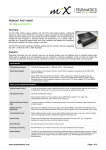
PRODUCT FACT SHEET FM3306 & FM3316 Overview The FM 3306 (without backup battery) and FM3316 (with backup battery), collectively referred to herein as the FM 3316, is the ideal on-board computer for the management of vehicle and driver performance, driver safety and vehicle utilization. The on-board computer enables the fleet manager to remotely monitor the performance of a vehicle. Data is recorded on a second-by-second basis with driver violations and detailed trip information being made available to the fleet manager in real-time. The FM 3316 on-board computer interfaces directly with the vehicle’s data bus supporting the CAN - J1939 and J1708 - J1587 standards. Features Recording information from the vehicle’s data bus has several benefits over the traditional way of recording vehicle data. Where data is available up to 20 parameters may be monitored in real-time, installation of the unit does not require the connection of expensive 3rd party sensors, installation is quicker, more robust and the recorded data is more accurate. CAN SUPPORT CAN Interface Standard The FM3316 supports CAN – J1939 and J1708 – J1587 standards. Vehicle Data Support When available on the vehicle’s CAN bus, the FM 3316 is capable of recording up to 20 parameters in real-time: Speed, RPM, fuel consumption, fuel tank level, PTO, coolant level, coolant temperature high, Oil pressure high, Oil level low, clutch over-load, maximum axle weight, brakes applied, clutch engaged, total engine hours, vehicle odometer, distance to next service, TCO drive recognize, TCO over speed and TCO direction indicator. VEHICLE AND DRIVER MANAGEMENT Vehicle Access Control A driver tag (code-plug) is used to identify and verify a driver. An optional starter interrupt can be used to immobilize the vehicle until such time as the driver presents an authorised driver tag. Trip Data Recording Standard recorded data includes: Date and time, Distance or hours, Speed or hours, RPM, Power takeoff, Fuel* usage, Trip start/depart/arrive/end time, Driver name and ID, Vehicle ID Second-to-Second (Tacho) Data The status of speed and RPM is recorded every second. This provides valuable in-depth information for accident analysis. Violation & Event Monitoring Standard event violations include: Over speed, Over revving (RPM), Over green band driving (low and high), Harsh braking, Rapid acceleration, Excessive idling, Overtime driving, Power takeoff (true or false) Customizable Events Define additional custom events such as panic button pressed, door open, no-go zone entered, sudden impact, warning lights activated, refrigerator temperature exceeded, etc. Active Events Receive data messages when selected standard or user-defined events occur, e.g. a cargo door opening in a no-go zone, driver arrived at customer location. Driver Warning A buzzer can be set to sound when an event occurs. Servicing & Licensing Set reminders for your vehicle’s next service or for your vehicle/driver license expiry. Backup Battery The FM 3316 is equipped with an internal Backup Battery offering an additional layer of security, making tracking possible even if the vehicle’s main battery has been disconnected. The Backup Battery starts to operate as soon as the supply to the main vehicle battery is cut. The FM 3306 does not include a Backup Battery. www.mixtelematics.com Page 1 of 5 www.mixtelematics.com LOCATIONS Manage Locations Add any desired location such as customer, supplier or no-go zones. Route Planning Plan routes by entering stops, start times and duration of each stop. This can serve as daily job activity sheets for your drivers. Active/Passive Tracking or Active Trail Request the vehicle position in real-time or view the route taken after the trip has been downloaded. Active tracking (AVL) function can be disabled from the unit prior to shipping. GPS Data Recording A variety of positional information is recorded with every GPS point, e.g. vehicle and driver ID, date and time, latitude and longitude, altitude, heading, speed, number of satellite etc. COMMUNICATION Downloading from/uploading to Vehicle The GSM modem is used to download data from and upload data to the FM 3316. This allows for realtime tracking and immediate active event notifications. It is possible to upgrade firmware or update the configuration remotely over-the-air using the GSM modem, thus reducing the need to remove the vehicle from duty when performing maintenance. Satellite Communication Satellite communication allows limited data download from and upload to the FM 3316 when using the optional FM Sat Comms transceiver. This provides real-time tracking and event monitoring when out of GSM coverage. FM Sat Comms provides global coverage except at the extreme poles of the earth. Voice Calls GSM voice communication is possible when using the optional FM Voice Kit, which allows for hands-free operation. General information The FM3316 includes: GSM/GPRS Antennae. GPS Antennae. Main harness with integrated buzzer includes the CAN interface wires in addition to conventional I/O wires (2 x frequency inputs, 3x digital / analogue input). FM3316 code-plug harness and socket. Blue driver’s plug (driver log-on). FM on-board computer user manual. J1708 2-wire harness Optional harnesses: serial harness, voice harness, I/O harness (2x frequency input, 5x digital / analogue input, ground and positive drive) Technical description Voltage Range 9V DC – 33V DC. Input Protection Automotive 24V load dump (160V, 2 Ohm, 400mS); short duration low-energy & high-energy transients). ISO7637 Part 1, 2 and 3 Clock Real time with independent battery back-up. Firmware Re-programmable firmware and configuration over wired and wireless media. Ignition Input Used to monitor the ignition switch status. I/O Capabilities 8* digital / analogue inputs, 1* auxiliary frequency input, 1 relay drive output, 1 positive drive output, 1 starter interrupt, 1 RS232 serial interface, 1 CAN interface, 1 J1708 interface. * The eighth input (I8) is shared with the fourth frequency input (F4) CAN Normal operating speed: ~250Kbits per Sec. Maximum operating speed: ~1Mbits per Sec. Protection (DC): -27V to +40V. Page 2 of 5 www.mixtelematics.com J1708 Normal operating speed: ~9600bits per Sec. Maximum operating speed: ~9600bits per Sec. Protection (DC): -60V to +60V. Inputs, Outputs & Events Highly configurable inputs and events capable of output control. Audio Interface This interface allows the user to make voice calls using the optional FM Voice Kit, FM Keypad and FM3316 Voice Kit Harness. Buzzer & LED The FM3316 has a buzzer and LED to warn the driver and to provide feedback of the vehicle’s status. I2C Bus Intended for use with code-plugs used to identify drivers, calibrate, diagnose faults, upload firmware and new configurations, and to download logged data and unit specific configuration information. This bus can also be used to drive the FM Keypad which can be used for selecting driving reasons and allows the driver to make voice calls when used with the FM Voice Kit. TTL Level Serial Port Intended to be used by devices designed to work on a bus. The bus was specified to be a Multi-Master type to enable other intelligent devices to optionally work as master, relieving the FM3316 of processing. Memory Memory comprises 2MB of flash and 31KB of RAM. 352KB is dedicated to storing firmware, 312KB for event data, 128KB for tacho data and 384KB for buffering data. Technical specifications ENVIRONMENT Temperature Temperature (Storage): -10° to +55°C Temperature (Operating): -10° to +55°C Temperature (Charging): 0° to +45°C Temperature (Discharging): -10° to +50°C Circuit Protection Conformal coating over the PCB and all components (excluding connectors). SUPPLY Current (Operating) <42mA at 28V (typical)* (Sleep) <20mA at 28V (typical)* (Operating) <70mA at 12V (typical)* (Sleep) <30mA at 12V (typical)* (Powered down) <2mA at 12V (typical) (Powered down) <3mA at 28V (typical) * The signal strength on the GSM affects the current consumption. The firmware running on the FM3316 micro processor affects the current consumption of the unit. RELAY CIRCUIT Current Specifications 200mA (typical). Maximum Continuous Voltage on Pin 33V Protection Transients will be clamped EMC Tests 72/245/EEC as last amended by 95/54/EC (Radiated Emissions – compulsory tests; and Radiated Immunity – non-compulsory tests) EN 61000-6-3 (Generic Standard Emission - Residential, commercial and light industry) EN 61000-6-2 (Generic Standard Immunity – Industrial Environment) Page 3 of 5 www.mixtelematics.com RS232 PORTS Maximum Speed 57600 Baud (higher rates possible with hardware flow control) Protection (Transient) 15Kv as per human body model Protection (DC) -12V , +12V 2 I C BUS Normal Operating Speed ~38Kbits per second Maximum Supply Current (CLK) <20mA Protection (Transient) 15Kv as per human body model Protection (DC) 0V to +12V REAL TIME CLOCK Time Loss <10 Minutes per year (typical)/ <5 seconds when a GPS is used (auto synchronization)* Battery Backup Life >5 Years (typical at -30° to +70°C) *temperature change affects the accuracy of the RTC crystal, it’s most accurate at +25°C. GPS Channels 16 Update Rate 1Hz Accuracy Position 2.5m CEP Accuracy DGPS/SBAS 2.0m CEP Start-up Time < 2 Minutes GPS Operating Temperature -40°C to 85°C GSM GPRS Multi-slot class 10 Tri Band EGSM900/DSC1800/PSC1900 For voice, data, text messages (SMS) and fax. Transmit Power Class 4 (2W) for EGSM900 Class 1 (1W) for DSC1800/PCS1900 Operating Temperature -20°C to 55°C -25°C to 70°C (limited functionality) SIM Card 3V Page 4 of 5 www.mixtelematics.com Auxiliary inputs/outputs 8 Configurable Analogue or Digital Inputs 8* analogue or digital inputs can be configured to monitor any device that generates a change in voltage. E.g. seat belts, headlights, refrigeration units, temperature sensors, emergency lights, doors, PTO, UDS, trailer coupling etc. Voltages are measured in the range of 0 – 38 volts in steps of approximately 0.15 volts. Inputs may be programmed to measure voltages between 0 and 5 volts in increments of approximately 0.02 volts. * The eighth input (I8) is shared with the fourth frequency input (F4) 1 Frequency Input An auxiliary frequency input can be configured to monitor any device that generates a change in frequency e.g. liquid flow measurement or as a pulse counter e.g. electronic fuel consumption measurement (EDM). Frequencies of up to 150Hz can be measured or low board rate encoded RS232 inputs of up to 75 baud. * The fourth frequency input (F4) is shared with the eighth input (I8) 1 Relay Drive Output The relay drive output can be used to drive a relay (with a current consumption of up to 150 mA) that can power a peripheral device on or off. 1 Positive Drive Output Used to power external devices. Battery voltage -2V DC. It can supply current up to 1A. 1 Starter Interrupt The FM3316 has a dedicated starter interrupt. A relay socket comes fitted to the main power harness for this purpose. 1 RS232 Serial Interface This can be connected to any RS232 serial device using the FM3316 Serial Harness. 1 TTL Serial Interface The FM Terminal can be connected using the FM3316 Serial Harness. The FM Twin Serial Harness can be used to convert this to a standard RS232 port to connect a second serial device. CAN Interface This can be connected to a J1939 CAN bus using the yellow / green twisted wires on the main connector. J1708 Interface This can be connected to a J1708 bus using the separately supplied yellow / blue twisted wire. Page 5 of 5