1
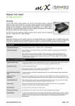
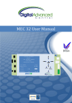
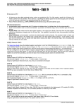
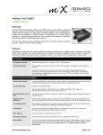
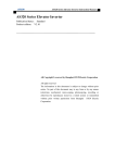
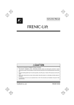
May 17, 2010 Indicator Control Card User Manual INDICATOR CONTROL CARD USER MANUAL Contents 1. Introduction ................................................................. 4 1.0 Standard Features. ..................................................... 4 2. Indicator Control Card Layout ....................................... 5 3. Electrical Connections ................................................... 9 4. Indicator Control Card MMI Interface .......................... 10 5. Changing A Parameter ................................................ 12 6. 5.1 Example of changing the position from 1 to G ........ 13 5.2 ICC Menu Structure (Indicator Setup) ...................... 17 5.3 ICC Menu Structure (Factory Setup) ........................ 18 5.4 ICC Menu Structure (Board Management) .............. 19 5.5 ICC Menu Structure (ICC Test Mode) ....................... 20 5.6 ICC Parameters......................................................... 21 Maintenance Required ............................................... 25 Appendix A Electrical & Mechanical Data ........................ 27 2 YSP 11/11 VER 1.0 INDICATOR CONTROL CARD USER MANUAL Revision History: Date Revision 01/09/2011 1.0 Description Initial Deployment Changed By YSP Unit2, Faraday Close, Daventry, Northamptonshire NN11 8RD. [email protected] Tel: +44(0)1327 879334 3 INDICATOR CONTROL CARD USER MANUAL 1. Introduction The SF750 indicator control card has been designed to act as an interface between a lift controller and the Digital Advanced Control range of dot matrix indicators and TFT LCD screens. The indicator control card is a fully featured programmable unit which includes speech, real-time and date, full opto-isolation and controller area network (C.A.N) communication. The unit is operated from 12/24 V A/C or D/C and it's a small compact unit designed to fit on DIN Rail. 1.0 Standard Features. A user-friendly interface to allow changes to be made to the indicators and TFT displays on site. Programmable inputs including line per floor, binary, grey-code, inverted binary and seven segment inputs. Input monitoring via the on-board liquid crystal display. Real time and date from a super accurate real-time clock. Positive and negative common inputs as standard. Self test features to simplify commissioning. Controller area network C.A.N. On board speech as standard. Designed, manufactured and technical support in the UK. 4 YSP 11/11 VER 1.0 INDICATOR CONTROL CARD USER MANUAL 2. Indicator Control Card Layout The indicator control card consists of a main PCB board which includes power and input stages, connections for communication and a speaker, a LCD and an operator keypad. There are LED's to give indication of successful communication and operation of the card. Setup menus are accessed via the operator interface which is designed to be both flexible and user-friendly. Unit2, Faraday Close, Daventry, Northamptonshire NN11 8RD. [email protected] Tel: +44(0)1327 879334 5 INDICATOR CONTROL CARD USER MANUAL Connections AC1/AC2 CH/CL SP1/SP2 M1 M2 M3 M4 M5 M6 M7 DOI DCI PT SX HU HD IU ID MC PC P1-P8 LED LOOP 3V3 5V TX RX Description AC/DC Input Serial data (C.A.N)output Speaker output Lift overloaded Lift under fire control Lift under fire alarm operation Lift on inspection control Lift out of Service Lift on Evacuation Control CUSTOM speech input(doors opening) speech input(doors closing) position trigger Un-used Hall Lantern up input Hall Lantern down input scrolling arrow up input scrolling arrow down input message common position common position inputs 1 to 8 Voltage 12-24V 12-24V 12-24V 12-24V 12-24V 12-24V 12-24V 12-24V 12-24V 12-24V 12-24V 12-24V 12-24V 12-24V 12-24V 12-24V 12-24V 12-24V 12-24V Description Loop Led, If not beating then the microprocessor has failed. Indicates the 3V3 supply is present Indicates the 5V supply is present Can port 1 transmit LED Can port 1 receiver LED 6 YSP 11/11 VER 1.0 INDICATOR CONTROL CARD USER MANUAL Real-time clock The real-time clock is provided by a super accurate real time clock with an internally temperature compensated calibrated clock to ensure the real-time clock is accurate to + or -3.5 ppm. This Real-time clock includes the minutes, hours, day, date, month and year information. This automatically adjusted for months with fewer than 31 days including corrections for the leap years. The clock operates in a 24 hour format, and a 3.2v battery which provides backup of the time and date (Should be changed every 5 years). Power supply The power supply to the unit is from 12/24 V DC utilising a DC to DC switch mode power supply is reduced to 5V and 3.3V on the board, the microprocessor has its own on-board regulator for generating the 1.8 V and is supplied from 3.3 V. The board is a 4 layer board and has separate power and ground planes internally sandwiched inside the board. C.A.N drivers The microprocessor board has a controller area Network (C.A.N) device to implement a network for controlling the indicators. The communication is at 250K bits/s and uses the Peli-Can V2.0B mode with 11 bit identifiers. The transceiver is a MCP2551 CAN chip on the left hand side of the board. LED indication of the network is provided, when the LEDs are flashing brightly at a rate of 1 Hz, this indicates there is no bus communication with the indicator devices. If the LEDs flash Unit2, Faraday Close, Daventry, Northamptonshire NN11 8RD. [email protected] Tel: +44(0)1327 879334 7 INDICATOR CONTROL CARD USER MANUAL dimly and at a much faster rate, then communication with the indicator devices is successful. Contrast potentiometer The contrast of the display of the microprocessor can be adjusted by the contrast pop located on the top left-hand side of the microprocessor. Speech Unit The indicator control card has an on-board speech unit included. This provides a digitised speech output with a carrier frequency of 21.6 kHz. The digitised speech is filtered and then amplified using the latest D Class amplifier technology allowing for a heat-sink less design, compact size and clarity of sound. 8 YSP 11/11 VER 1.0 INDICATOR CONTROL CARD USER MANUAL 3. Electrical Connections Unit2, Faraday Close, Daventry, Northamptonshire NN11 8RD. [email protected] Tel: +44(0)1327 879334 9 INDICATOR CONTROL CARD USER MANUAL 4. Indicator Control Card MMI Interface The MMI interface of the MEC32 is a Alphanumeric character LCD display which has 5 push buttons to navigate the setup menus. The buttons are configured in an intuitive arrangement similar to most modern day mobile phones allowing for ease of operation. 10 YSP 11/11 VER 1.0 INDICATOR CONTROL CARD USER MANUAL The buttons are as follows: UP = UP browse/adjust parameter button DN = DOWN browse/adjust parameter button LEFT = Left browse button RIGHT = Right browse button ENTER = Confirm/Enter button SETUP = gives access to the configuration menus. The display also gives information on the inputs as can be seen in the diagram overleaf, these are position inputs, message inputs, speech and indicator input operation. Unit2, Faraday Close, Daventry, Northamptonshire NN11 8RD. [email protected] Tel: +44(0)1327 879334 11 INDICATOR CONTROL CARD USER MANUAL 5. Changing a Parameter The ICC has a simple intuitive graphical MMI interface to set the parameters of the indicator system. The menus are configured from a set of main menus then into Sub-menus where the parameters can be accessed. The system can be navigated by pressing the setup button and then using the arrows to browse through the main menu to select the sub-menu required. Once the submenu is selected (notated by the > < arrows on the far left and far right hand side of the display) then the enter/confirm button can be used to select the submenu. Once in the submenu to select the desired parameter to be changed and then press the confirm button, you will then enter the parameter change display. Press the confirm button again and the parameter to be changed will flash. The parameter now may be changed using the up and down buttons and selecting the required value. Once the required value is displayed, press the Enter/ Confirm button and the parameter will stop flashing. The parameters will remain stored for at least 99 years after power removal. An example of changing the position at a floor is shown in the diagrams overleaf. 12 YSP 11/11 VER 1.0 INDICATOR CONTROL CARD USER MANUAL 5.1 Example of changing the position from 1 to G Unit2, Faraday Close, Daventry, Northamptonshire NN11 8RD. [email protected] Tel: +44(0)1327 879334 13 INDICATOR CONTROL CARD USER MANUAL 14 YSP 11/11 VER 1.0 INDICATOR CONTROL CARD USER MANUAL Unit2, Faraday Close, Daventry, Northamptonshire NN11 8RD. [email protected] Tel: +44(0)1327 879334 15 INDICATOR CONTROL CARD USER MANUAL 16 YSP 11/11 VER 1.0 INDICATOR CONTROL CARD USER MANUAL 5.2 ICC Menu Structure (Indicator Setup) Unit2, Faraday Close, Daventry, Northamptonshire NN11 8RD. [email protected] Tel: +44(0)1327 879334 17 INDICATOR CONTROL CARD USER MANUAL 5.3 ICC Menu Structure (Factory Setup) 18 YSP 11/11 VER 1.0 INDICATOR CONTROL CARD USER MANUAL 5.4 ICC Menu Structure (Board Management) Unit2, Faraday Close, Daventry, Northamptonshire NN11 8RD. [email protected] Tel: +44(0)1327 879334 19 INDICATOR CONTROL CARD USER MANUAL 5.5 ICC Menu Structure (ICC Test Mode) 20 YSP 11/11 VER 1.0 INDICATOR CONTROL CARD USER MANUAL 5.6 ICC Parameters The Indicator Control Card has a built-in can port to act as a control interface to the serial data SF750 digital position indicators and clear view range of TFT Indicators. The settings each of the parameters is described in the table below. 1.0.0.0 SF750 indicator Description parameter 1.1.0.0 Indicator Setup 1.1.1.0 Position Input Setup 1.1.2.0 Position Input Type These parameters allow you to Set up the indicators This parameter allows you to change what position is displayed on the indicator display. This allows you to change the selected inputs from the following options: DISC – Line Per Floor BIN – Binary INVERT BIN – Inverted Binary GRAY – Gray Code SEVEN SEG – Seven Segment 1.1.3.0 Lowest Level Sets the lowest level of the lift inputs 1.1.4.0 Highest Level Sets the number of floors of the Lift 1.1.5.0 Brightness Setup Set the intensity level of the indicators Unit2, Faraday Close, Daventry, Northamptonshire NN11 8RD. [email protected] Tel: +44(0)1327 879334 21 INDICATOR CONTROL CARD USER MANUAL 1.1.6.0 Display Zero Position 1.2.0.0 Message Setup 1.2.1.0 Message setup 1.3.0.0 Speech Setup 1.3.1.0 Announce All FL Displays a base position with no inputs These parameters allow you to set up the messages. This parameter allows the message to be written for each message input i.e. When the microprocessor outputs lift overloaded the standard message of lift overloaded will be displayed this could be changed to lift overloaded please reduce the load. The lift overloaded message which is message one will only ever be displayed on the car. These parameters allow you to set up the functionality of the speech module This parameter is set when announcing of the floors is required as each floor is passed without a speech position trigger. 1.3.2.0 Speech Volume This parameter adjusts the level of the volume from the speech module, between 0-100%. 1.3.3.0 Quiet volume This parameter adjusts the level of the volume when the speech 22 YSP 11/11 VER 1.0 INDICATOR CONTROL CARD USER MANUAL module is in quiet mode, between 0-100%. The Quiet mode selection can be adjusted in the timed event settings. 1.4.0.0 Arrow setup 1.4.0.0 Direction arrow type 1.5.0.0 Scroll speed setup 1.5.1.0 Position scroll speed 1.5.2.0 Message scroll speed These parameters allow you to set up the functionality of the scrolling arrows. This selects the type of direction arrow to be displayed. These parameters allow you to set the scrolling speeds of the indicators. This parameter selects the speed of the scrolling position. This parameter selects a speed of the scrolling messages. 1.5.3.0 Arrow scroll speed This parameter selects the speed of the scrolling arrows. 1.6.0.0 Hall arrow and These parameters allow you to set the functionality of Hall arrow and gongs This parameter selects the type of hall arrow to be displayed. Gong set up 1.6.1.0 Hall arrow type 1.6.2.0 Hall Gong This parameter if set to yes, turns Unit2, Faraday Close, Daventry, Northamptonshire NN11 8RD. [email protected] Tel: +44(0)1327 879334 23 INDICATOR CONTROL CARD USER MANUAL on the hall gongs This parameter if set to yes turns on the car gong only 1.6.3.0 Car Gong 1.7.0.0 No Entry Setup 1.7.1.0 No Entry Setup This parameter sets if message input Displays the NO ENTRY Symbol 2.0.0.0 Board Management These parameter set the Board configuration Parameters 2.1.1.0 Date And Time This parameter sets the time and date of the real time clock for displaying the time on the Clear View indicators 2.1.1.0 DLight Saving This parameter sets if the day light saving is ON or OFF 2.2.0.0 ICC Test Modes These parameters set up the self test modes of the Indicator Control Card 2.2.1.0 Position Check This parameter displays the position on the position indicators automatically. 2.2.2.0 Message Check This parameter displays the messages automatically on the indicators 24 YSP 11/11 VER 1.0 INDICATOR CONTROL CARD USER MANUAL 2.2.3.0 Speech Check This parameter checks the speech and speaker operation 2.2.4.0 No Entry Check This parameter will display the NO ENTRY Sign on the indicators when set. Unit2, Faraday Close, Daventry, Northamptonshire NN11 8RD. [email protected] Tel: +44(0)1327 879334 25 INDICATOR CONTROL CARD USER MANUAL 6. Maintenance Required The Indicator Control Card its self is a solid state device, has few user serviceable parts and requires little maintenance, but the indicator control card will require the following to be done with the power off: Note: Electronic boards contain static sensitive devices and should not be touched unless you have the required protection. Every 5-7 Years: Change the Battery in the Microprocessor. Date Changed.................................... Date Changed..................................... Date Changed..................................... Date Changed..................................... 26 YSP 11/11 VER 1.0 INDICATOR CONTROL CARD USER MANUAL Appendix A Technical Specification Electrical Data Microprocessor Input Voltage 12 - 24VDC +/- 10% Relay Board Input Voltage 24VDC +/- 10% Maximum current of the 0.25A Indicator Control Card. Maximum power consumption of 2 Watts the Indicator Control Card. Relay board maximum current 0.15A consumption Internal Voltages 5V, 3V3 and 1.8V Microprocessor Specification Microprocessor Type 32Bit RISC Microcontroller with a MIPS32®M4K™ core operating at 60MHz and 90MIPS. Can Ports 1 Can ports operating at 250Kbits/Sec with a maximum bus length of 200m terminated by 120Ω resistor. Real Time Clock Super accurate real time clock with an internal temperature compensated clock frequency with a drift of +/- 3ppm. Display 4x20 STN Alphanumeric White On Blue LCD Display with LED Backlight. Dimensions Dimensions 195mm x 115mm x 40mm Weight 250 grammes Inputs 12 - 24V DC inputs Can be switched positively and negatively draw 5mA each input. Unit2, Faraday Close, Daventry, Northamptonshire NN11 8RD. [email protected] Tel: +44(0)1327 879334 27 INDICATOR CONTROL CARD USER MANUAL Operational Temperatures Maximum Operating 60°C Temperature Maximum Ambient Temperature 40°C Minimum Operating -10°C Temperature EMC Compliance BS EN12015:2004: Lifts, Emissions Escalators & Passenger Conveyors BS EN55022:2006 + A1:2007 Class A: Emissions Standard for Information Technology Equipment Immunity BS EN12016:2004: Lifts, Escalators & Passenger Conveyors BS EN61000-4-2:1995: Electrostatic Discharge BS EN61000-4-3:2002: Radiated Immunity BS EN61000-4-4:1995: Fast Transient Bursts BS EN61000-4-5:1995: Surges BS EN61000-4-6:1996: Conducted Immunity 28 YSP 11/11 VER 1.0 INDICATOR CONTROL CARD USER MANUAL If you require support at any stage please do not hesitate to contact us. Tel: 01327 879 334 Fax: 01327 877 087 E-Mail: [email protected] We Also Provide Free Training at Our Offices in Northamptonshire Unit2, Faraday Close, Daventry, Northamptonshire NN11 8RD. [email protected] Tel: +44(0)1327 879334 29