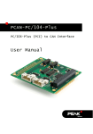
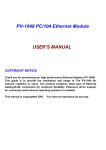
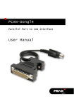
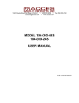
1
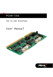
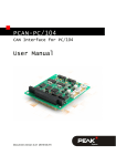
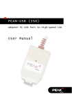
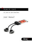
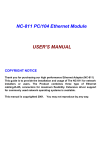
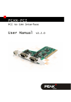
PCAN-ISA
CAN Interface for ISA
User Manual
PCAN-ISA – User Manual
Products taken into account
Product Name
Model
Item Number
PCAN-ISA Single Channel
One CAN channel
IPEH-002074
PCAN-ISA Dual Channel
Two CAN channels
IPEH-002075
PCAN-ISA Single Channel
opto-decoupled
One CAN channel, galvanic
isolation for CAN connection
IPEH-002076
PCAN-ISA Dual Channel
opto-decoupled
Two CAN channels, galvanic
isolation for CAN connections
IPEH-002077
The cover picture shows the product PCAN-ISA Dual Channel opto-decoupled. Other
product versions have an identical form factor but vary in equipment.
Product names mentioned in this manual may be the trademarks or registered
trademarks of their respective companies. They are not explicitly marked by “™” and
“®”.
Copyright © 2015 PEAK-System Technik GmbH
Duplication (copying, printing, or other forms) and the electronic distribution of this
document is only allowed with explicit permission of PEAK-System Technik GmbH.
PEAK-System Technik GmbH reserves the right to change technical data without
prior announcement. The general business conditions and the regulations of the
license agreement apply. All rights are reserved.
PEAK-System Technik GmbH
Otto-Roehm-Strasse 69
D-64293 Darmstadt
Germany
Phone: +49 (0)6151-8173-20
Fax:
+49 (0)6151-8173-29
www.peak-system.com
[email protected]
Issued 2015-06-16
2
PCAN-ISA – User Manual
Contents
1
1.1
1.2
1.3
2
Introduction
4
Properties at a Glance
System Requirements
Scope of Supply
Hardware Installation
4
5
6
7
2.1 Configuring the PCAN-ISA Card
2.2 Installation into the Computer
2.3 Modifying the Computer's BIOS Settings
2.3.1 Indicating Used Interrupts
2.3.2 Deactivating the APIC Mode
2.4 Connecting a CAN Bus
2.5 5-Volt Supply at the CAN Connector
7
10
11
11
12
13
14
3
Software Setup
16
4
Software
17
4.1
4.2
PCAN-View for Windows
Linking Own Programs with PCAN-Light
17
19
5
Frequently Asked Questions (FAQ)
21
6
Technical Specifications
22
Appendix A
CE Certificate
24
Appendix B
Quick Reference
25
3
PCAN-ISA – User Manual
1
Introduction
Tip: At the end of this manual (Appendix B) you can find a
Quick Reference with brief information about the installation
and operation of the PCAN-ISA card.
The PCAN-ISA card enables simple, cost-effective connection of
computer systems with ISA slots to CAN networks. Multiple PCANISA cards can easily be operated using interrupt sharing.
The card is available as a single or dual-channel version. The optodecoupled versions also guarantee galvanic isolation of up to 500
Volts between the PC and the CAN sides.
Note: This manual refers to different versions of the PCAN-ISA
card (see also Products taken into account on page 2).
Differences at use and at the technical specifications are
mentioned accordingly in this manual.
1.1
Properties at a Glance
PC plug-in card for 16-bit ISA slots
13 port and 8 interrupt addresses are available for configuration
using jumpers
Multiple cards can be operated in parallel in a single PC
(interrupt sharing)
Compliant with CAN specifications 2.0A (11-bit ID) and
2.0B (29-bit ID)
NXP SJA1000 CAN controller, 16 MHz clock frequency
NXP PCA82C251 CAN transceiver
4
PCAN-ISA – User Manual
Connection to CAN bus through D-Sub slot bracket, 9-pin (in
accordance with CiA® 102)
Bit rates from 5 kbit/s up to 1 Mbit/s
Galvanic isolation on the CAN connection up to 500 V (only
opto-decoupled versions), separate for each CAN channel
5-Volt supply to the CAN connection can be connected through a
solder jumper, e.g. for external bus converter
Extended operating temperature range from -40 to 85 °C
(-40 to 185 °F)
Note: This manual describes the use of the PCAN-ISA card with
Windows. You can find device drivers for Linux and the
corresponding information on PEAK-System's website under
www.peak-system.com/linux.
1.2
System Requirements
An empty ISA slot (16 bit) in the computer
Operating system Windows 8.1, 7, Vista (32/64-bit)
or Windows CE 6.x (x86 and ARMv4 processor support)
or Linux (32/64-bit)
5
PCAN-ISA – User Manual
1.3
Scope of Supply
PCAN-ISA card
Slot bracket with D-Sub connectors for the CAN bus
Device drivers for Windows 8.1, 7, Vista and Linux (32/64-bit)
Device driver for Windows CE 6.x
(x86 and ARMv4 processor support)
PCAN-View CAN monitor for Windows 8.1, 7, Vista (32/64-bit)
PCAN-View CAN monitor for DOS
PCAN-Basic programming interface consisting of an interface
DLL, examples, and header files for all common programming
languages
Manual in PDF format
6
PCAN-ISA – User Manual
2
Hardware Installation
2.1
Configuring the PCAN-ISA Card
Before you install the PCAN-ISA card into the computer you may
need to configure it. For each CAN channel an interrupt (IRQ) and an
I/O address range is set for operation in the computer.
At delivery the PCAN-ISA card has the following default settings:
CAN Channel IRQ
I/O Address Range
1
10
300h – 31Fh
2
5
320h – 33Fh
Remark
Only on the Dual Channel version
Tip: If the given resources are not firmly occupied by other
devices, you can skip the configuration and directly continue
with the following manual section 2.2.
For a configuration differing from the default settings you need to
set jumpers on the PCAN-ISA PCB according to the following
explanations.
Position of the Jumper Fields on the PCAN-ISA Card
The single-channel version of the PCAN-ISA card has two jumper
fields, one for the setting of the I/O address range and one for the
setting of the interrupt (Figure 1). Accordingly the Dual Channel
version has the doubled layout (Figure 2).
7
PCAN-ISA – User Manual
Figure 1: PCAN-ISA Single Channel – Position of the jumper fields for setting
the I/O address range (JP1, left marker)
and the interrupt (JP3, right marker)
Figure 2: PCAN-ISA Dual Channel – Position of the jumper fields for setting
the I/O address ranges (JP1, JP2, left marker)
and the interrupts (JP3, JP4, right marker)
I/O Address Range
Each CAN channel must be assigned to an unique I/O address range
in the computer. An address space from 200h up to 39Fh (h =
hexadecimal) is available. The PCAN-ISA card uses 32 addresses
beginning from the configured base address. The configuration is
done on jumper field JP1 for CAN channel 1 and jumper field JP2
for CAN channel 2 (latter only with the Dual Channel version).
8
PCAN-ISA – User Manual
The following table shows the possible settings. The X stands for a
set jumper. The default settings at delivery for CAN channels 1 and
2 are highlighted.
Jumper field JP1/JP2
A
B
C
D
E
X
200h – 21Fh
X
X
X
X
X
X
X
X
X
X
X
X
X
X
X
X
X
X
X
X
X
X
X
260h – 27Fh
X
2A0h – 2BFh
X
2E0h – 2FFh
2C0h – 2DFh
X
X
220h – 23Fh
240h – 25Fh
280h – 29Fh
X
X
I/O address range
300h – 31Fh
X
X
X
X
320h – 33Fh
340h – 35Fh
X
360h – 37Fh
380h – 39Fh
Interrupt
An interrupt (IRQ) must be assigned to each CAN channel. The
PCAN-ISA card supports the interrupts 3, 4, 5, 7, 10, 11, 12, and 15.
The default setting at delivery for CAN channel 1 is interrupt 10, for
CAN channel 2 interrupt 5.
It is possible to share the same interrupt between two existing CAN
channels. Therefore you can configure the same interrupt, when
using two PCAN-ISA cards in the same computer.
Tip: We suggest to configure different interrupts as long as
resources allow it and use interrupt sharing only, if this is not
the case.
9
PCAN-ISA – User Manual
2.2
Installation into the Computer
Do the following to install the PCAN-ISA card into the computer:
1.
Make sure that the computer is turned off (power switch at
the computer's supply unit).
2.
Open the casing and plug the PCAN-ISA card into an empty
slot on the computer's motherboard. For details please refer
to the documentation of the computer.
3.
In the computer replace a slot bracket with the supplied slot
bracket containing the D-Sub connector(s) for the CAN bus,
if applicable.
4.
For each CAN channel connect the flat cable to the
corresponding connector on the PCAN-ISA card.
You can look up the pin assignment of the 10-pin CAN
connectors on the card in section 0 on page 11.
Figure 3: Connectors for the cable(s) to the slot bracket (here: PCAN-ISA Dual
Channel, the single-channel version only has the left connector Ch1)
5.
Close the computer's casing.
Note: Before switching on the computer, please follow the
procedure for modifying the computer's BIOS settings
described in the following section.
10
PCAN-ISA – User Manual
2.3
Modifying the Computer's BIOS Settings
To ensure a flawless operation of the PCAN-PC/104 card it is necessary that you adjust settings in the BIOS setup of the computer:
Indicate used interrupts
Deactivate the APIC mode
Note: Due to a diversity of existing BIOS setup versions for
computers we cannot give detailed instructions here. Instead
we indicate common setting names.
In order to know how to start the computer's BIOS setup please
consult the corresponding documentation. Usually you can enter
the BIOS setup by pressing the Del or F2 key shortly after switching
on the computer.
2.3.1
Indicating Used Interrupts
By indicating the interrupts that are set on the PCAN-PC/104 card,
you avoid that the corresponding resources are automatically
assigned to other devices and that this results in conflicts.
In the BIOS setup itself you can often find the settings for the
interrupts under a menu item containing the text “PnP”. For the
interrupt(s) used by PCAN-PC/104 change the setting to “Reserved”
or “Legacy ISA”.
11
PCAN-ISA – User Manual
2.3.2
Deactivating the APIC Mode
Note: Do not mix up APIC with ACPI.
The APIC mode is a certain type of interrupt management in a
computer.
If the APIC mode is active in your computer, you must deactivate it
so that the PCAN-PC/104 card can work properly with interrupts.
Do the following to determine in Windows if the APIC mode is
active:
1.
Open the Windows Device Manager.
2.
Select the menu entry View > Resources by type.
3.
Open the branch of Interrupt request (IRQ).
If entries with interrupt numbers greater than 15 are listed,
the APIC mode is active and you must deactivate it.
Do the following to deactivate the APIC mode:
Important note: When you deactivate the APIC mode in the
BIOS setup, it may happen that you must reinstall Windows
afterwards, because it cannot start anymore due to the lowlevel setting.
1.
Restart the computer and switch to the BIOS setup.
2.
Search for the APIC setting and deactivate it.
3.
Save the changes in the BIOS and quit the BIOS setup.
4.
If Windows doesn't start properly, reinstall it or perform a
repair installation.
12
PCAN-ISA – User Manual
2.4
Connecting a CAN Bus
A High-speed CAN bus (ISO 11898-2) is connected to one of the
9-pin D-Sub ports on the slot bracket. The pin assignment
corresponds to the CiA recommendation DS 102-1.
Figure 4: Pin assignment HS-CAN
(view onto connector of the slot bracket)
The pin assignment between the D-Sub port and the 10-pin
connector on the PCAN-ISA card is as follows:
Figure 5: Numbering at the 10-pin connector
Pin
Assignment
Assignment D-Sub
1
+5 V (optional)
1
2
GND
6
3
CAN_L
2
4
CAN_H
7
5
GND
3
6
not connected
8
7
not connected
4
8
+5 V (optional)
9
9
not connected
5
10
not connected
13
PCAN-ISA – User Manual
2.5
5-Volt Supply at the CAN Connector
You can route a 5-Volt supply to pin 1 and/or pin 9 of the CAN
connector (independently for each CAN connector on the Dual
Channel version) by setting solder bridges on the PCAN-ISA card.
Thus devices with low power consumption (external transceivers or
optocouplers, for example) can be directly supplied via the CAN
connector.
When using this option the 5-Volt supply is connected to the power
supply of the computer and is not fused separately. The optodecoupled versions of the card contain an interconnected DC/DC
converter. Therefore the current output is limited to about 50 mA.
Attention! At this procedure special care is indispensable, since
there is a short circuit danger. The PCAN-ISA card could be destroyed and/or the power supply or electronics of the computer
or other components connected could be damaged.
Attention! Risk of short circuit! If the option described in this
section is activated, you may only connect or disconnect CAN
cables or peripheral systems (e.g. external transceivers or optocouplers) to or from the PCAN-ISA card while the computer is
de-energized.
Important note: PEAK-System Technik GmbH does not give
guarantee on damages which have resulted from application of
the option described in this section.
Set the solder bridge(s) on the card according to the desired settings. Figure 6 shows the positions on the card; the table below
contains the possible settings.
14
PCAN-ISA – User Manual
Figure 6: Position of the solder bridge fields for the 5-Volt supply
5-Volt supply →
None
Pin 1
JP5 (CAN channel 1) /
JP6 (CAN channel 2)
15
Pin 9
Pin 1 + Pin 9
PCAN-ISA – User Manual
3
Software Setup
This chapter covers the software setup for the PCAN-ISA card under
Windows.
Do the following to install the driver:
1.
Insert the supplied DVD into the appropriate drive of the
computer. Usually a navigation program appears a few
moments later. If not, start the file Intro.exe from the root
directory of the DVD.
2.
Select in the main menu Drivers, and then click on
Install now.
3.
Confirm the message of the User Account Control in relation
to "Installer Database of PEAK Drivers".
The setup program for the driver is started.
4.
Follow the instructions of the setup program.
16
PCAN-ISA – User Manual
4
Software
This chapter deals with the provided software and the software
interface to the PCAN-ISA card.
4.1
PCAN-View for Windows
PCAN-View for Windows is a simple CAN monitor for viewing and
transmitting CAN messages.
Installation
The installation is done during the driver installation (see also
chapter 3 Software Setup on page 16).
Program Start
Open the Windows Start menu or the Windows Start page and
select PCAN-View.
The dialog box for selecting the hardware and for setting the
parameters appears.
17
PCAN-ISA – User Manual
Figure 7: Selection of the CAN specific parameters
If no entry is in the list “Available CAN hardware” (for example at
the first program start), you need to add one:
1.
Press the button Add. The dialog box “Add CAN hardware”
appears.
2.
Select the connected hardware and the operating mode
from the list “Type of CAN hardware”.
18
PCAN-ISA – User Manual
Figure 8: Selection of hardware resources
3.
Enter the I/O base address and the interrupt set on the
PCAN-ISA card (see section 2.1 Configuring the PCAN-ISA
Card on page 7).
4.
Confirm your input with OK.
In the dialog box “Connect to CAN hardware” you may make
further settings (baud rate and CAN message filter) for the created
hardware entry.
If you need further help after the program start, use the online help
provided with the program (F1 key).
4.2
Linking Own Programs with PCAN-Light
On the supplied CD-ROM you can find files that are provided for
software development. You can access them with the navigation
program (button Programming). The files exclusively serve the
linking of own programs to hardware by PEAK-System with the help
of the installed device driver under Windows.
19
PCAN-ISA – User Manual
Further more the CD-ROM contains header files and examples for
creating own applications in conjunction with the PCAN-Light
drivers. Please read the detailed documentation of the interface
(API) in each header file.
Tip: You can find further information in the file
PCANLight_enu.chm (Windows Help file) on the CD-ROM.
Notes about the License
Device drivers, the interface DLL, and further files needed for linking
are property of the PEAK-System Technik GmbH (PEAK-System)
and may be used only in connection with a hardware component
purchased from PEAK-System or one of its partners. If a CAN
hardware component of third party suppliers should be compatible
to one of PEAK-System, then you are not allowed to use or to pass
on the driver software of PEAK-System.
PEAK-System assumes no liability and no support for the PCANLight driver software and the necessary interface files. If third party
suppliers develop software based on the PCAN-Light driver and
problems occur during use of this software, please, consult the
software provider. To obtain development support, you need to
own a PCAN-Developer or PCAN-Evaluation version.
20
PCAN-ISA – User Manual
5
Frequently Asked Questions
(FAQ)
Question
Answer
Can I use several PCAN- Yes. When there's a lack of resources it
is possible to share the same interrupt
ISA cards in the same
between CAN channels. However,
computer?
consider that an unique I/O address
range is assigned to each CAN channel.
21
PCAN-ISA – User Manual
6
Technical Specifications
Connectors
Computer
ISA bus with 8 MHz clock rate, 16 bit bus width
CAN
D-Sub (m), 9 pins
Pin assignment according to CiA recommendation
DS 102-1
Opto-decoupled versions: galvanic isolation up to 500 V
(separate for each CAN channel)
CAN
Specification
ISO 11898-2
High-speed CAN (up to 1 MBit/s)
2.0A (standard format) and 2.0B (extended format)
Controller
max. 2 Philips SJA1000T
Transceiver
max. 2 Philips PCA82C251
Supply
Current consumption
PCAN-ISA Single Channel:
PCAN-ISA Dual Channel:
PCAN-ISA Single Channel opto-dec.:
PCAN-ISA Dual Channel opto-dec.:
Environment
Operating temperature
-40 – +85 °C (-40 – +185 °F)
Temperature for storage -40 – +125 °C (-40 – +257 °F)
and transport
Relative humidity
15 – 90 %, not condensing
EMC
EN 55024:2011-09
EN 55022:2011-12
EC directive 2004/108/EG
Continued on the next page
22
max. 150 mA
max. 170 mA
max. 210 mA
max. 270 mA
PCAN-ISA – User Manual
Measures
Size
143 x 66 x 13 mm (5 5/8 x 2 5/8 x 1/2 inches)
Weight
PCAN-ISA Single Channel:
PCAN-ISA Dual Channel:
PCAN-ISA Single Channel opto-dec.:
PCAN-ISA Dual Channel opto-dec.:
23
39 g
45 g
41 g
48 g
PCAN-ISA – User Manual
Appendix A
CE Certificate
24
PCAN-ISA – User Manual
Appendix B
Quick Reference
Default setting at delivery
CAN Channel IRQ
I/O Address Range
1
10
300h – 31Fh
2
5
320h – 33Fh
Remark
Only on the Dual Channel version
Hardware Installation / Configuring the Computer
Insert the PCAN-ISA card into a free ISA slot (16 bit) of the switched
off computer. After switching on the computer enter the BIOS setup.
In the PnP table mark the interrupts used by the PCAN-ISA card as
reserved.
Software setup and startup under Windows
Execute the driver installation program from the supplied CD-ROM.
Run the CAN monitor PCAN-View from the Windows Start menu as
a sample application for accessing the PCAN-ISA card. Indicate the
needed parameters for initialization of the PCAN-ISA card (I/O base
address, interrupt) and select the desired CAN channel, when using
the Dual Channel version.
HS-CAN connector (D-Sub, 9 pins)
25