1
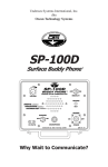
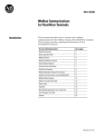
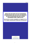
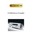
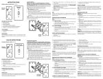
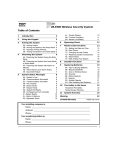
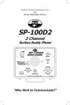
PARAGON ELECTRIC, INC.
LIQUID LEVEL CONTROLLER USER
MANUAL
MODELS:
LLC-I, LLC-II
AND TELEMETRY OPTIONS
2
Table of Contents
Safety ........................................................................................ 4
Introduction................................................................................ 5
Features and Benefits ............................................................... 6
Control Overview....................................................................... 7
Selector Switches............................................................................ 7
Panel Display (PanelView 300 Micro) ............................................. 7
Navigation ................................................................................. 8
Menus........................................................................................ 9
Main Screen .................................................................................... 9
Alarms........................................................................................... 12
Troubleshooting ............................................................................ 12
Pump Statistics ............................................................................. 13
Setpoints ....................................................................................... 15
Pump Mode ............................................................................. 16
Alternate Mode.............................................................................. 17
Pump 1 Lead Mode....................................................................... 17
Pump 2 Lead Mode....................................................................... 17
Both Pumps Run Mode ................................................................. 17
Specifications .......................................................................... 18
Troubleshooting....................................................................... 19
Replacement Parts.................................................................. 23
Dimensions and Layout........................................................... 24
Options .................................................................................... 25
Telemetry Option for LLC.............................................................. 25
Telemetry Option for Slave Unit .................................................... 25
Surge Protection ........................................................................... 27
Wiring Diagrams and Terminations ......................................... 28
3
Safety
The products discussed in this manual utilize electrical energy
which can be hazardous or fatal. Do not open the panel cover
unless all power to the panel has been removed.
WARNING: Note that it is possible for there to me more than one
power source available in the control panel (such as control power
and chemical metering pump power). Be sure to de-energize and
lock out all potential power sources to the panel.
Wear safety goggles and insulated gloves to check that all power
has been removed in panel using a rated tester.
If you are not sure how to deal with the inside of this panel safely,
call a registered electrician.
4
Introduction
The Paragon Electric, Inc. Liquid Level Controller automatically
controls water storage tank level utilizing pressure sensing at well
or pumphouse locations. The LLC-I controls one well pump and
the LLC-II controls two well pumps. Pumps are turned on and off
based on tank level setpoints defined by the user.
5
Features and Benefits
With the Paragon Electric, Inc. Liquid Level Controller, nothing is
installed at the storage tank. Tank Level sensing is accomplished
at the pumphouse. The control panel and pressure transducer are
installed in one location for ease of use and maintenance. Pump
start/stop and running pressures are automatically filtered out of
the transmission line to provide accurate tank level indication.
In addition to tank level control the LLC-I and LLC-II have the
following features and benefits:
1. Tank level indication
2. Pump status logging including:
• Elapsed run time
• Pump starts for each pump
• Pump fails for each pump.
3. Alarming including:
• High and low tank levels
• Pump failure
• Transducer or transducer cable failure
• Radio signal loss (telemetry option only)
4. Pump running status indication
5. Pump run mode selection (LLC-II only) including:
• Alternate
• Pump 1 Lead
• Pump 2 Lead
• Both pumps run simultaneously
6. The control panel is manufactured using reliable,
industrial-grade parts which are all readily available.
7. Equipment is protected from surges by fusing and two
levels of surge suppression. Controller components are
further protected by power supply isolation. The main
components are all 24VDC.Setup and operation is easy due
to the enhanced graphical user interface. The user enters
tank height, current tank level and tank levels with one or
more pumps running to automatically calibrate the unit for
tank level monitoring (see installation section of the manual).
6
Control Overview
Well pumps are controlled using the selector switches on the front
of the panel and by using the panel display (PanelView 300).
Selector Switches
Each pump can be controlled with the Hand-Off-Auto selector
switch provided on the front of the Liquid Level Controller. (The
LLC-I has one selector switch and the LLC-II has two.)
HAND
Hand mode will run the pump regardless of whether the controller
is calling for automatic run or not. Hand mode will work even if
controller components have failed or controller power is off.
OFF
Off mode will not allow the pump to run.
AUTO
Auto mode will run the pump based on the user defined setpoints.
When the storage tank level drops to the start setpoint the pump
will start and run until the storage tank level reaches the stop
setpoint. (More details on auto mode can be found in the pump
mode section of the manual.)
Panel Display (PanelView 300 Micro)
Access to the Liquid Level Controller processor information is
accomplished by using the panel display interface. Tank level,
pump run status, pump statistics, as well as other information can
be viewed using this display. Setpoints such as pump start level
and stop level can be viewed and changed through the display as
well. In addition, startup and calibration data can be viewed and
changed. No computer is needed to setup the Liquid Level
Controller.
7
Navigation
To navigate the controls use the “F” keys and navigation arrows
located on the display.
“F” keys are used to select the four major menus as well as select
objects in the display area. Left and right arrows can be used to
navigate within a selected menu or to navigate within a selected
entry such as a setpoint. Up and down arrow keys are used to
change values of data. The enter key is used to select highlighted
menu choices or confirm entered data.
8
Menus
The Paragon Electric Liquid Level Controller has four main
menus. These menus are selected using the “F” buttons on the
bottom of the user display. For convenience, these four menus are
shown just to the right of the controller.
F1
F2
F3
F4
MAIN SCREEN
ALARMS
PUMP STATS
SETPOINTS
Main Screen
The main screen shows the time and date as well as tank level
and pump status. The tank level is shown in feet from the bottom
of the storage tank floor. The pump status will indicate if a pump is
running or has failed (see troubleshooting). For LLC-I units only
one pump running or fail indication will be available. For LLC-II
units, status information of two pumps will be available.
Tank Level
The tank level is displayed and represents the water level in feet
above the water storage tank floor.
9
Pump Running Status
If either pump is running (only one pump for the LLC-I) the screen
will display “PUMP 1” or “PUMP 2” or both depending on which
pump or pumps is running.
F1
F2
F3
F4
10
MAIN SCREEN
ALARMS
PUMP STATS
SETPOINTS
Pump Fail Status
If a pump is in hand mode or in auto mode and is being called to
run, but the controller does not sense a running condition, a pump
fail indicator will be shown such as, “P1 FAIL” or “P2 FAIL” (only
one pump for the LLC-I). These indicators will flash in order to
draw attention. If the controller senses that either pump has failed,
the common alarm relay will be energized and any attached alarm
output will be actuated (such as an alarm beacon). Check the
troubleshooting section of this manual for details of pump fail
indication and causes.
The main screen will also indicate if an alarm is present as
indicated by the flashing alarm banner.
F1
F2
F3
F4
11
MAIN SCREEN
ALARMS
PUMP STATS
SETPOINTS
Alarms
If the ALARM indicator is flashing the alarm menu can be
accessed by pressing the “F2” button. This screen will show any
present alarms. Under normal conditions none of the alarms
shown below should be present. Acknowledging the alarms will
turn off the common alarm relay, which will turn off any attached
alarm output (alarm beacon, autodialer, etc.)
Note: F1, F3 and F4 still access the MAIN, PUMP STATS AND
SETPOINTS menus respectively.
Troubleshooting
The troubleshooting menu provides access to the controller’s
troubleshooting feature. Using the up and down arrows, screens
can be accessed for each alarm condition. Press the up or down
arrow until the desired troubleshooting page is found and then
press enter.
12
Here a text will be displayed to briefly explain alarm condition as
well as possible solutions.
To get back to the alarm screen use the left arrow key.
Note: F1, F3 and F4 still access the MAIN, PUMP STATS AND
SETPOINTS menus respectively.
Pump Statistics
Using the “F3” button will take you to the “PUMP STATS” screen.
This screen has useful pump information such as run-time, pump
starts and pump fails. Keeping track of this information can help
assure that the pump is running a reasonable amount of time for
each start and that it is not “failing” frequently. (See
troubleshooting section of this manual if numerous fails are noted
over any period of time.)
13
PUMP STATS
PUMP 1
PUMP 2
135
HOURS
148
29
STARTS
31
2
FAILS
0
F1
F2
F3
F4
MAIN SCREEN
ALARMS
PUMP STATS
SETPOINTS
The above screen shows the Pump Statistics screen for the LLCII. The LLC-I will not show any hours, starts or fails for “PUMP 2.”
By dividing the “HOURS” by the “STARTS”, the average run time
can be determined for each pump. In this case pump one is
running an average of 4.66 hours per start (135/29=4.66). Pump
fails can be caused by a number of situations. See the
troubleshooting section of this manual for more information.
Generally, there should be few or no fails.
Note: the Pump Statistics screen can be reset to zero if desired in
one of the advanced setup menus. (See the Advanced section of
this manual for details.)
14
Setpoints
For setup and or to choose tank-level start and stop setpoints
access the “SETPOINTS” menu by pressing the “F4” button.
F1
F2
F3
F4
SETPOINTS
F1-MAIN MENU
F2-START
F3-STOP
14 FT
16 FT
MAIN SCREEN
ALARMS
PUMP STATS
SETPOINTS
FORWARD ARROW - MORE
The “SETPOINTS” screen allows the user to change start and
stop setpoints as well as navigate to setup and advanced screens.
The “F2” button allows the user to enter the start setpoint and the
“F3” button allows entry of the stop setpoint. For example: To set
the start setpoint, press F2. A numeric data entry screen will be
shown. Use the up/down arrows to increase or decrease the
number. The left and right arrows will allow moving from one
numeric place holder to another. Enter a whole number. Fractions
or decimals are not allowed. Once the desired number is shown
on the screen press the enter key. This will return you to the
Setpoint screen.
Accessing additional screens is possible using the RIGHT
(referred to as FORWARD ARROW on the display). These
screens are for setup and advanced configuration and require a
password. See the ADVANCED section of this manual for more
information.
15
Generally, after initial setup, the only keys needed are the “F” keys
to navigate between menus. The “SETPOINTS” menu is used
during setup and to enter stop and start points for the pump.
Otherwise only menus 1, 2, and 3 are needed for general
monitoring of the system. To utilize other functions of the unit
advanced screens can be accessed using a password.
Pump Mode
By pressing the forward (right) arrow on the setpoints screen, the
pump mode screen can be accessed. Use the up/down arrow
keys to select the desired pump mode from the menu. When the
arrow to the left of the menu points to the desired mode, press
enter.
PUMP MODE
ALTERNATE
PUMP 1 LEAD
PUMP 2 LEAD
BOTH RUN
USE UP AND DOWN
ARROWS TO SELECT
PUMP MODE.
LEFT ARROW – RETURN
RIGHT ARROW - ADVANCED
THEN PRESS ENTER
The left arrow changes the screen to the previous screen. The
right arrow changes the screen to the advanced screen which
requires a password to access.
The following mode descriptions apply to the LLC-II. If your
controller is an LLC-I, the “PUMP 1 LEAD” mode should be
selected.
16
Alternate Mode
The alternate mode alternates pumps based on call for water
signals created within the processor. In other words, when the
tank level drops below the start setpoint, the first pump in the
sequence is started and will run until the tank level reaches the
stop setpoint. When the tank level again falls below the start
setpoint, the next pump will start and will run until the tank level
once again reaches the stop setpoint. This sequence will continue
indefinitely. If for some reason the tank level drops one foot below
the start setpoint, both pumps will be called to run. If the tank level
drops two feet below the start setpoint, then the “Low Tank” alarm
will be set.
Pump 1 Lead Mode
Use this pump mode if the LLC-I is installed or if it is desired to run
pump 1 more than pump 2, set the mode to “PUMP 1 LEAD.” The
controller will start pump 1 every time the tank level drops below
the start setpoint. Pump 2 will start only if the tank level continues
to drop one foot below the start setpoint. If the tank level drops two
feet below the start setpoint, then the “Low Tank” alarm will be set.
Pump 2 Lead Mode
If it is desired to run pump 2 more than pump 1, set the mode to
“PUMP 2 LEAD.” The controller will start pump 2 every time the
tank level drops below the start setpoint. Pump 1 will start only if
the tank level continues to drop one foot below the start setpoint. If
the tank level drops two feet below the start setpoint, then the
“Low Tank” alarm will be set.
Both Pumps Run Mode
Use this mode if it is desired that both pumps run simultaneously.
When the tank level drops below the start setpoint, both pumps
will start and fill the tank until the stop setpoint is reached. If the
tank level drops two feet below the start setpoint, then the “Low
Tank” alarm will be set.
17
Specifications
Electrical
Power supply
Power
Alarm relay rating
Control power fusing
120VAC, 15 or 20A
84 watts max.
7.5A @ 120VAC
5A slow acting @ 120VAC
¼” x1 ¼”
1A fast acting @ 24VDC
¼” x1 ¼”
24VDC fusing
Physical
Dimensions
Weight
Enclosure rating
Operating temperature
16” H x 14” W x 8” D
12.6 lbs.
NEMA4
32°F to 10°F
18
Troubleshooting
PROBLEM
POSSIBLE CAUSE
Controller has no
power.
Controller fuse is
blown.
Shut off power to controller. (see
safety section at the beginning of this
manual). Check fuses by visual
inspection. (see illustration on page
22.)
Selector switch or
switches in
“HAND” mode.
Turn selector switches to off or auto.
Controller is not
configured
properly.
Check that setpoints are within the
range of the tank. Check that tank
level reading on the display is the
same as actual tank level.
Display blank
Tank level is
high.
SOLUTION
Check the circuit breaker that feeds
the controller. Make sure utility power
is available.
Controller selector
Check that selector switch or switches
switch or switches
are in hand or auto mode.
in “OFF” mode.
Tank level is
low.
Pump has no
power.
Check that circuit breakers which feed
the pump are on and not tripped.
Check that there is utility power
available.
Pump has failed.
See pump failed section below.
Controller not
configured
properly.
Check that setpoints are within the
range of the tank. Check that tank
level reading on the display is the
same as actual tank level.
19
Xducer fail.
The pressure
transducer is not
registering with
the controller.
Look for obvious problems such as a
damaged cable at the transducer. Call
installer for repair or replacement.
PLC Fault
The controller is
faulted.
Call the installer for repair or
replacement.
The pump has no power. Check the
circuit breaker that feeds the pump
and that there is utility power available.
Pump 1 failed
The controller is
calling the pump
to run, but does
not sense that the
pump is running.
The pump overloads have tripped.
Reset overloads. Multiple tripping
usually indicates a pump problem.
Consult well pump manual or call well
pump installer.
A motor saver associated with this
pump is tripping. Consult the motor
saver manual or call the installer of the
motor saver.
Pump 2 failed
Same as pump 1
fail.
Same as pump 1 fail.
RF Fail
The telemetry
signal is weak or
missing. (This is
only if telemetry
option is
installed).
Check that antennas or antenna cable
has not been damaged. Check for
obstructions that could interfere with
the line of site, such as trees or shrubs
that have grown in the radio path. Call
the installer.
20
Over-frequent
pump starts
Motor never
shuts off.
Setpoints
incorrectly
configured
Check to see that the start and stop
setpoints are adequately spaced. The
greater the difference in the setpoints
the longer the pump or pumps will run.
Incorrect pump
mode.
Try switching to an alternating mode
on a two pump system if the mode is
currently set to “BOTH PUMPS RUN.”
Motor saver is
tripping.
Check to see that a motor saver or
other device is not tripping and then
automatically resetting. The pump
should run for long periods (at least
two hours) without stopping.
System leak.
Check for leaks in the water system.
Pump output too
small.
Check that pump is producing proper
flow. Check that appropriate valves
are open.
21
24VDC fuse – 1A fast acting
Control fuse – 5A slow acting
The most common problem with the controller is a blown controls
fuse. This typically happens after a power surge occurs due to
such occurrences as a lightning storm. If the display is blank and
power is known to be at the building, check for a tripped circuit
breaker. If this is not the case, remove power to the controller and
check for a blown fuse (see safety procedures at the front of this
manual).
The Control fuse is the most likely to blow in the event of surges.
Unscrew the black knob till the fuse is released. There should be a
small wire filament visible in the glass. If there is not replace with a
spare (spares are provided with the controller). There are two
types of spares used, the “slow-blow” which has a thicker element
than the “fast blow”.
22
Replacement parts
Qua
Item
Brand
Model
Enclosures and Backplates
1
Enclosure Nema 12R
Carlon
NS16146
1
Backplate for above
Carlon
JP1614
Relays
5
Ice cube 1 pole
Idec
RH1B-UL-120V
5
Bases for above
Idec
SH1B-05
Terminal Blocks
9
Double deck TB, 300V, 20A, 70mmx5mm, 28-12AWG
Wago
870-501
10
End cap for 870-501 above
Wago
870-518
2
2 way Jumper bars for 870-501 above
Wago
870-402
2
Grounding TB 4 cond, 300V, 20A, 70mmx5mm, 28-12AWG
Wago
870-507
6
4 cond through block, 300V, 20A, 70mmx5mm, 28-12AWG
Wago
870-508
1
Fuse TB 1/4"x1 1/4" w/neon ind 120VAC, 10A,
Wago
282-128/281-418
1
End cap for 282-128/281-418 above
Wago
282-311
1
Fuse TB 1/4"x1 1/4" w/led ind, 24VDC
Allen
Bradley
1761-BWBL205A
Phoenix
Contact
2938840
Pressure
Systems
28-142-4-0065
PLC
1
Micrologix 1000 with analog input, 24VDC
1
Micro PV300
Power Supply
1
120VAC to 24VDC power supply,
Transducer
1
Pressure transducer, .5%, vented gauge, 4-20mA, 1/4"
Selector switch
2
3 position maintained selector SW, no blocks
Sq D
9001-KS43B
4
Contact blocks 1-NO/1-NC
Sq D
9001-KA1
Sq D
8910 DPA22
Contactors
1
Definite Purpose contactor, 2 Pole, 120V coil, 25A FLA
23
Dimensions and Layout
Radio
24
Options
Telemetry Option for LLC
Either the LLC-I or the LLC-II can be augmented to become a
telemetry master RTU. Funtion and programming is essentially the
same. Instead of connecting additional pumps to the process
through wiring, radio telemetry is used to control a remote pump.
Set-up and monitoring are the same as with the non-telemetry
controller. The main difference is the presence of an RF Fail
alarm to indicate to the user when the radio signal has been lost or
compromised.
Telemetry Option for Slave Unit
In addition to the option of adding a radio to the LLC, a slave unit
can be purchased in order to have a way to get the radio signal to
the remote pump. A radio slave unit is shown on page 26.
This unit has run, fail and elapsed time indicators as well. In
addition, the unit has a selector switch enabling the operator to
choose HAND-OFF-AUTO modes.
Lastly, there is a LOCAL-REMOTE switch which allows the
operator to choose between local and remote auto modes. For
example if the HOA selector is in AUTO mode and the
LOCAL/REMOTE switch is in remote mode, the master controller
will control the pump based on tank level setpoints. If the
LOCAL/REMOTE switch is turned to local the pump can be
controlled by a local device such as a timer.
Note that there is a timer in the telemetry slave. This Off-Delay
timer keeps the pump running for a short time after the radio
signal calls for the well to stop. The purpose of this is to prevent
cycling if the radio signal is weak. A brief interruption in the radio
signal will not be able to shut the pump off.
25
26
Alarm Beacon
The existence of a common alarm relay at the LLC (and also at
the Slave RTU if there is one) allows connection to an alarm
output. Most commonly this is an alarm beacon to indicate to the
user when any of a number of alarm conditions occur including:
• Low or High Tank
• PLC Fault
• Transducer Failure
• Pump Failure
• Radio Signal Failure (for telemetry options only)
The alarm beacon can be shut off by acknowledging the alarm
condition. This is done by pressing the “F2” button to get to the
alarm screen, and then the “F2” button again to acknowledge the
alarms.
Surge Protection
The LLC units, as well as Telemetry slave units, have built in
surge protection in the form of an air gap surge protector and a
silicon avalanche diode surge protector. It is recommended that
additionally the Pumphouse be protected by a surge protector
such as the Joslyn Z2-175. This unit has a visible window to
indicate if the unit is ok.
27
Wiring Diagrams and Terminations
28
© Paragon Electric, Inc.
Albuquerque, New Mexico
505 265-5883
www.paragon-electric.com
29