1
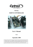
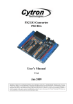
IFC-CI00
Interface Free Controller
Computer Interface
User’s Manual
V1.0
March 2010
Information contained in this publication regarding device applications and the like is intended through suggestion only and may
be superseded by updates. It is your responsibility to ensure that your application meets with your specifications. No
representation or warranty is given and no liability is assumed by Cytron Technologies Incorporated with respect to the accuracy
or use of such information, or infringement of patents or other intellectual property rights arising from such use or otherwise. Use
of Cytron Technologies’ products as critical components in life support systems is not authorized except with express written
approval by Cytron Technologies. No licenses are conveyed, implicitly or otherwise, under any intellectual property rights.
ROBOT . HEAD to TOE
Product User’s Manual – IFC-CI00
Index
1. Introduction and Overview
1.1 Introduction of Interface Free Controller
1.2 System Overview
2. Packaging List
3. Product Specification
3.1 Programming Tool
3.2 Input and Output device
3.3 Operating voltage
3.4 Batteries Status LEDs
3.5 USB Status LEDs
4. Board or Product Layout
5. Installation (Hardware)
6. Installation (Software)
7. Getting Started
7.1 Basic Setup (IFC-PC00 + IFC-CI00)
7.2 Basic Setup with Control Panel (IFC-PC00 + IFC-CI00 + IFC-CP04)
7.3 Setup for IFC System
8. Warranty
Created by Cytron Technologies Sdn. Bhd. – All Rights Reserved
0
ROBOT . HEAD to TOE
Product User’s Manual – IFC-CI00
1. INTRODUCTION AND OVERVIEW
1.0 Introduction of Interface Free Controller
IFC (Interface Free Controller) offer a new concept of developing microcontroller embedded
system and also robotics system. With IFC, no more frustration in determine hardware
interface and configuring peripheral in software. Checking few hundreds pages of data sheet
can be waved. With the concept of interfacing card, user may stack as many as 64 cards in a
system to get infinite combination of peripherals. The design aim is to offer 3 simple steps in
microcontroller system development – Configure card’s address, Stack IFC cards, Write
Program and Run!
Furthermore, with functions based software library, user save valuable time during software
development by concentrating on algorithm development. No more flipping or scrolling PIC
data sheet looking for ADCON0, T1CON or even TRISA. With just a programming hand
book, user may simply copy the header file, call comprehensive functions and it’s ready to
rock.
Computer Interface Card (IFC-CI00) is another main card for IFC system and may replace
IFC-MB00. It is designed for advance user to interface the IFC system and computer where
computer will become main controller. As computer is able to interface with powerful
sensors such as laser range finder and video camera, integrating with IFC will offer low level
control to motors, solenoid, relay, etc. It will become a virtual Com Port through USB
connection. User is free to send the command (refer to Card Library Function) to the IFC
system. This card has been designed with capabilities and features of:
• Industrial grade PCB.
• Every component is soldered properly and tested before board is shipped.
• 1 Reset button
• 4 Output LEDs
• Power, busy and error LED
• USB Status LEDs
• Battery Status LEDs
• 1 buzzer
• 5V operation
• Dimension 11.1cm x 6.9cm
• Sample source code is provided for Microsoft Visual C# 2008
This document explains the usage of IFC-CI00 (Computer Interface).
Caution: High current inductance load such as brush motor, may affect the USB signal of
this card. User is advised not to drive high current (above 5A) motor or inductance load
with IFC-CI00 as bridge to computer.
Created by Cytron Technologies Sdn. Bhd. – All Rights Reserved
1
ROBOT . HEAD to TOE
Product User’s Manual – IFC-CI00
1.1 System Overview
With serial communication perception, IFC offer million of possibilities to develop
embedded system creatively and easily. In IFC, several cards are stacked to get a complete
embedded system. The minimum card requires is Power Card and Main Board or Computer
Interface Card.
Newly designed in IFC systems is Computer Interface card (IFC-CI00). IFC-CI00 is
designed to replace IFC-MB00 to let computer as the main processor in IFC System. Some
advance sensors like Laser Range Finder and webcam is difficult to access by using
microcontroller therefore IFC-CI00 was designed to cover the limitation and that we call
unlimited potential of IFC system. Just plug a USB cable from computer to IFC-CI00 card
and a virtual COM Port will be created on your computer. Besides, user can plug more than
one IFC-CI00 cards in one computer.
More cards
More devices
Control Panel Card
RC Servo Card
RC Servo
Play station 2 Controller card
PS2 Controller
Analog Input Card
Analog sensor
Digital Input Card
Encoder, digital sensor
Output Card
Brushless Motor Card
Relays, etc
Brushless motors
Dual Brush Motor Card
2 Brush motors
Brush Motor Card (15A)
Brush motor
Computer Interface
Power card
Power and communication
Created by Cytron Technologies Sdn. Bhd. – All Rights Reserved
2
ROBOT . HEAD to TOE
Product User’s Manual – IFC-CI00
Computer
And more System 4, 5, 6…
Virtual COM port 1
To IFC-CI00
System 1
USB Cable
Virtual COM port 3
Virtual COM port 2
To IFC-CI00
To IFC-CI00
System 3
System 2
More than one IFC-CI00 can be plugged to a computer as shown as above. USB hub can be
used to expand your USB port if needed. Please do remind that each IFC slave card MUST
has a UNIQUE address in every system (except IFC-CP04) but the address can be repeated or
same for other slave card which placed in another system as shown as above. It is NOT allow
more than one IFC-CI00 card in a system. Please refer to chapter 7.3 for software setting for
the cards’ address.
Created by Cytron Technologies Sdn. Bhd. – All Rights Reserved
3
ROBOT . HEAD to TOE
Product User’s Manual – IFC-CI00
2. PACKAGING LIST
Please check the parts and components according to the packing list. If there are any parts
missing, please contact us at [email protected] immediately.
1. 1 x IFC-CI00 with:
• 1 x 2510H
• 2 x 2510H Iron Pin
• 1 x USB Cable (B Type)
• 1 x CD which contained 3 folders. The folders are Documentation (consist of IFCCI00 User’s Manual, IFC Library Functions card for VCS & VB), Installer (consist of
Visual Studio software), sample source codes for IFC-CI00).
Created by Cytron Technologies Sdn. Bhd. – All Rights Reserved
4
ROBOT . HEAD to TOE
Product User’s Manual – IFC-CI00
3. PRODUCT SPECIFICATION
3.1 Programming Tool
No programming tool used in IFC-CI00. User may control IFC system easily by plug a USB
cable from PC/laptop to IFC-CI00 card.
3.2 Input and Output device
The input and output device on CI00 are as below:
• 3 status indicator LEDs: Power and busy LED:
- Power LED (PWR) will turn ON when power is supplied to BH02.
- Busy LED (Busy) will turn ON or blinking when IFC slave card is
communicating with IFC-CI00.
- Error LED (Error) will turn ON if the one or more IFC slave cards’
address is not compatible to the program.
• 4 programmable indicator LEDs
• 2 battery status LEDs
• 2 USB status LEDs
• 1 buzzer
3.3 Operation Voltage
The operation voltage of IFC-CI00 is 12V. User need to stack a Power Card, IFC-PC00, and
connect a 12V battery on Power Card to supply 12V to the Computer Interface card. If 24V is
needed, 2 x 12V batteries are connected on Power Card to supply 24V.
3.4 Batteries Status LEDs
‘Batt1’ and ‘Batt2’ is representing Battery 1’s status and Battery 2’s status respectively. The
information of the status is printed on IFC-CI00 card as shown on table below. Please do
remind that this indicator only valid for 12V battery. Do not let the LED reaches to fast blink
status, please charge the battery if one of the LEDs is blinking to save your battery’s life
time.
Battery Status
LED On
: >11V
Slow Blink : <11V
Blink
: <10V
Fast Blink : <9V
LED Off
: No Battery
3.5 USB Status LEDs
These two LEDs are used to indicate the USB status. If IFC-CI00 first plugs in a new USB
port, the given IFC-CI00’s driver should be installed. Only LED 2 will blink and LED 1 off
(Address State) when installation until the driver is successfully installed. After the driver is
installed properly, these two LEDs will alternate blink at the time (Configured State), ready
to use! Both LEDs will blink at the same time in USB Suspend State. Both LEDs will off if
IFC-CI00 does not connect to computer.
Created by Cytron Technologies Sdn. Bhd. – All Rights Reserved
5
ROBOT . HEAD to TOE
Product User’s Manual – IFC-CI00
4. BOARD OR PRODUCT LAYOUT
A
B
C
D
N
M
E
F
F
G
L
Label
A
B
C
D
E
F
G
K
Function
USB connector type-B
Battery status table
Reset extension connector
Orientation marking
28 pin PIC microcontroller
Side connector
Buzzer
I
J
Label
H
I
J
K
L
M
N
H
Function
Batteries status LED indicator
USB status LED indicator
Output LED
Reset button
Status indicator LED
Manufacturing Test Points
Arrow
A – USB connector type-B which connected to PC or laptop
B – Explanation for two batteries’ status using two LEDs which labeled in ‘H’. Each LED
represents each battery’s status.
C – This reset extension connector is used for extending the reset button out of the IFC
system.
D – The orientation marking on IFC-CI00. Every IFC card will have this orientation marking,
this is to help user in ensuring the cards are stack correctly.
E – 28 pin PIC microcontroller which used as controller for this card.
F – This side connector is used for card stacking and communication between cards.
Created by Cytron Technologies Sdn. Bhd. – All Rights Reserved
6
ROBOT . HEAD to TOE
Product User’s Manual – IFC-CI00
G – Active High 5V buzzer.
H – ‘Batt1’ and ‘Batt2’ is representing Battery 1’s status and Battery 2’s status respectively.
The information of the status is printed on IFC-CI00 card as shown on table below. Please do
remind that this indicator only valid for 12V battery. Do not let the LED reaches to fast blink
status, please charge the battery if one of the LEDs is blinking to save your battery’s life
time.
Battery Status
LED On
: >11V
Slow Blink : <11V
Blink
: <10V
Fast Blink : <9V
LED Off
: No Battery
I – These two LEDs are used to indicate the USB status. If IFC-CI00 first plugs in a new
USB port, the given IFC-CI00’s driver should be installed. Only LED 2 will blink and LED 1
off (Address State) when installation until the driver is successfully installed. After the driver
is installed properly, these two LEDs will alternate blink at the time (Configured State), ready
to use! Both LEDs will blink at the same time in USB Suspend State. Both LEDs will off if
IFC-CI00 does not connect to computer.
J – 4 active High LEDs
K – This reset button is used for resetting all IFC slave cards but it would NOT reset IFCCI00 itself.
L – 3 status indicator LEDs to indicate status for power ON (PWR), busy in communication
with other cards (Busy) and program error (Error). PWR LED will ON when power supplied
to the board. Busy LED will ON when the card is busy in communication with other slave
card like Output Card, Control Panel and Digital Input card. Error LED will ON when the
address set on slave card did not match with the address in main program.
M – Reserved for Manufacturing Test Point. Please DO NOT short or connect wire to any of
these pins.
N – An arrow mark to help user in ensuring the cards are stack correctly. Every IFC card will
have this arrow mark; user needs to ensure that the arrow points to the same direction when
IFC cards are stack together.
Created by Cytron Technologies Sdn. Bhd. – All Rights Reserved
7
ROBOT . HEAD to TOE
Product User’s Manual – IFC-CI00
5. INSTALLATION (HARDWARE)
For the hardware installation of IFC-CI00, user will first need the Power Card (IFC-PC00)
and Computer Interface (IFC-CI00) of IFC system. IFC-CI00 is replacing IFC-MB00 in IFC
system. IFC-CI00 and IFC-MB00 cannot be used together in same system. The details about
IFC-PC00 card are available in IFC-MB00A User's Manual.
Main power supply:
• 1 x 12V battery.
• If 24V is needed, 2 x 12V batteries must be connected to Power card to provide 24V.
1. Stack IFC-PC00 and IFC-CI00 card together.
2. Connect battery to Power Card, IFC-PC00.
Connect 1 x 12V battery
to supply operating
voltage to IFC. Ensure
the polarity is correct.
Created by Cytron Technologies Sdn. Bhd. – All Rights Reserved
8
ROBOT . HEAD to TOE
Product User’s Manual – IFC-CI00
If 24V is needed in the
system, connect 2 x 12V
batteries to PC00.
Ensure the polarity is
correct.
3. Ensure every card is being stack properly in correct orientation.
Ensure the arrow points to the
same direction.
Ensure the orientation
marking at the same side.
Cautions: Please ensure that all card pins are not shifted when stacking. IFC system
will NOT function if the pins are shifted.
Created by Cytron Technologies Sdn. Bhd. – All Rights Reserved
9
ROBOT . HEAD to TOE
Product User’s Manual – IFC-CI00
4. Besides stack every card in correct orientation, user must also require to ensure all card
pins are not shifted when stacking. Figures show the example of stacking cards in proper
location and example of stacking cards with shifted pins.
Ensure that all card pins
are not shifted when
stacking.
Examples of stacking
cards with shifted pins.
Please AVOID this!
5. Connect USB cable (B type) to IFC-CI00 USB socket as shown in following figure,
another end (A type) to PC/laptop.
Connect to PC or
laptop
Connect to battery
Created by Cytron Technologies Sdn. Bhd. – All Rights Reserved
10
ROBOT . HEAD to TOE
Product User’s Manual – IFC-CI00
6. Computer will detect “Found New Hardware” when the first time user connects USB
cable from IFC-CI00 USB socket to PC/laptop. Only USB status LED 2 will blink and
LED 1 off until the driver is installed then both LEDs will alternate blink (ready to use).
To ensure the COM Port connect to IFC-CI00, go to My Computer> right click and select
Properties or while holding the windows key, press the Pause / Break key then click
Hardware>Device Manager. Device Manager Window appears and user can see IFCCI00 Computer Interface Card at the Ports (COM & LPT).
7. Yellow mark at IFC-CI00 Computer Interface port is because the driver is not installed
yet. Window Found New Hardware Wizard will launch when it detect new hardware plug
into PC or laptop.
Created by Cytron Technologies Sdn. Bhd. – All Rights Reserved
11
ROBOT . HEAD to TOE
Product User’s Manual – IFC-CI00
8. Select “Yes, this time only” from the options available and then click “Next” to proceed
with the installation.
9. Select “Install from a list or specific location (Advanced)” as shown below and then click
“Next”.
Created by Cytron Technologies Sdn. Bhd. – All Rights Reserved
12
ROBOT . HEAD to TOE
Product User’s Manual – IFC-CI00
10. Select “Search for the best driver in these locations” and click browse button to browse
the location. Location is a location for folder where users copy the IFC-CI00 installation
Driver. Click next to proceed.
11. Wait while the wizard search IFC-CI00 hardware.
Created by Cytron Technologies Sdn. Bhd. – All Rights Reserved
13
ROBOT . HEAD to TOE
Product User’s Manual – IFC-CI00
12. If following screen displayed, click on “Continue Anyway” to continue with the
installation.
13. Windows will display a message that the installation was successful. Click “Finish” to
complete the installation. Both USB status LEDs will alternate blink at this time (device
ready to use).
Created by Cytron Technologies Sdn. Bhd. – All Rights Reserved
14
ROBOT . HEAD to TOE
Product User’s Manual – IFC-CI00
14. After installation is complete, IFC-CI00 is ready to use. At device manager, user will see
the COM Port for IFC-CI00. From the example below, COM Port for IFC-CI00 is
COM14.
15. Turn ON the power on Power Card by pushing the toggle switch to “ON” label, the PWR
LED of IFC-CI00 and IFC-PC00 will turn ON as shown in Figure.
PWR LED on
IFC - CI00
12V LED on
IFC - PC00
Created by Cytron Technologies Sdn. Bhd. – All Rights Reserved
15
ROBOT . HEAD to TOE
Product User’s Manual – IFC-CI00
To open the cards, user can use the IFC card’s opener to open the stacked cards. Figure
shows the method to open cards with the opener. Please ensure the power is OFF before
inserting or removing IFC card.
1
2
3
Caution: Please use the opener to open IFC cards to avoid damage to pins or cards.
Created by Cytron Technologies Sdn. Bhd. – All Rights Reserved
16
ROBOT . HEAD to TOE
Product User’s Manual – IFC-CI00
6. INSTALLATION (SOFTWARE)
Visual Studio C # 2008 Express Editions is required to be installed in order for user to
create graphical user interface and write program. Visual C# (C Sharp) is a relatively new
language introduced by Microsoft along with Visual Studio. C# is fully object-oriented,
compatible with many other languages using the .NET Framework. C# is designed to allow
the programmer to develop applications that run under Windows and/or in a Web browser
without the complexity generally associated with programming. With very little effort, the
programmer can design a screen that holds standard elements such as buttons, check boxes,
radio buttons, text boxes, and list boxes.
6.1 Visual C# Installations
If user have already purchased and installed Visual Studio 2008 and C#, user can skip
this section. If users haven’t installed C#, this section will explain the method to install these
software and next section will briefly discuss on method to use it. User can get Visual C#
software from CD which is come together with IFC-CI00 card.
1. Click the executable file that was supplied. (The file was named Setup HTML
Application)
Created by Cytron Technologies Sdn. Bhd. – All Rights Reserved
17
ROBOT . HEAD to TOE
Product User’s Manual – IFC-CI00
2. Click Visual C # 2008 Express Editions to install that software.
3. Setup will copy required resources to user temp directory.
Created by Cytron Technologies Sdn. Bhd. – All Rights Reserved
18
ROBOT . HEAD to TOE
Product User’s Manual – IFC-CI00
4. Wait for one or two minute while setup is loading installation components.
5. After loading installation is complete, user should see a screen similar to that shown in
figure below. Then click next.
Created by Cytron Technologies Sdn. Bhd. – All Rights Reserved
19
ROBOT . HEAD to TOE
Product User’s Manual – IFC-CI00
6. Choose ‘I have read and accept the license terms’ and click next to proceed to the next
phase of the installation.
7. Select optional product and click next to start installation.
Created by Cytron Technologies Sdn. Bhd. – All Rights Reserved
20
ROBOT . HEAD to TOE
Product User’s Manual – IFC-CI00
8. Select the location where user would like to install Microsoft Visual C# 2008 Express
Editions. Browse to other location if user doesn’t like to install in default destination.
Click install.
9. The following items are being installed on user computer. Wait for awhile.
Created by Cytron Technologies Sdn. Bhd. – All Rights Reserved
21
ROBOT . HEAD to TOE
Product User’s Manual – IFC-CI00
10. After installation complete, click exit.
Created by Cytron Technologies Sdn. Bhd. – All Rights Reserved
22
ROBOT . HEAD to TOE
Product User’s Manual – IFC-CI00
6.2 Using Visual C#
To start Visual C# 2008 Express Editions, please follow the steps below:
1. To start project, create a main project folder. For example IFC-CI00. Users are
recommended to copy all dll file/folder and xml file/folder from the CD provided into
main project folder. It is because all dll file and xml file should be place in the same
folder with the project file.
2. Click on the icon installed on the desktop after installation or select Start>All
Programs>Microsoft Visual C# 2008 Express Edition. User should see a C# Express
startup screen shown in figure below.
Created by Cytron Technologies Sdn. Bhd. – All Rights Reserved
23
ROBOT . HEAD to TOE
Product User’s Manual – IFC-CI00
3. To create a project, move the cursor to File menu option from the main menu program
menu bar. The screen should look like what is shown in figure below.
4. Select New Project from the menu. The program screen changes as shown in figure
below. In figure below, users are given a number of predefined project templates from
which to choose. These templates define the types of programs that user may develop
with C#. From the templates shown below, select the Windows Application template.
User should also type the name of the project. For example IFC Sample. Then click OK.
Created by Cytron Technologies Sdn. Bhd. – All Rights Reserved
24
ROBOT . HEAD to TOE
Product User’s Manual – IFC-CI00
5. Figure below show the place user will spend time for programming. It’s called the
Integrated Development Environment or IDE because every programming tool user need
to write C# programs is available there.
Run Icon
Windows Form
Solution Explorer
Window
Properties
Window
Toolbar Window
Created by Cytron Technologies Sdn. Bhd. – All Rights Reserved
25
ROBOT . HEAD to TOE
Product User’s Manual – IFC-CI00
6. To add references in project, right click on Reference at Solution Explorer Window, then
click on Add References…, figure below shown the example for add references.
7. After clicking Add References…, an Add Reference window pop up.
Created by Cytron Technologies Sdn. Bhd. – All Rights Reserved
26
ROBOT . HEAD to TOE
Product User’s Manual – IFC-CI00
8. Click Browse to browse user main project folder (IFC-CI00). Then browse sub folder of
main project folder (IFC-CI00) which consist dll file. Do make sure the Files of type is
Component Files (*.dll;*.tlb;*.olb;*.ocx;*.exe;*.manifest)
9. Click on one of dll file and click OK to add reference in project.
Created by Cytron Technologies Sdn. Bhd. – All Rights Reserved
27
ROBOT . HEAD to TOE
Product User’s Manual – IFC-CI00
10. User may repeat the similar Add reference steps to add others dll files.
Add references for
IFC card
11. After added all the necessary files, user may start create project with adding objects to a
Windows Form. Don’t forget to change the text of label objects at Properties Window.
Window to
change text of
label object
Created by Cytron Technologies Sdn. Bhd. – All Rights Reserved
28
ROBOT . HEAD to TOE
Product User’s Manual – IFC-CI00
12. To view code, user click view code in Solution Explorer or click View menu option>Code
from the menu bar. To click view code in Solution Explorer, make sure user click
Form1.cs in the Solution Explorer first and small icon will appear at the top of Solution
Explorer. Below is example of source code. Programming writing is at this place.
Created by Cytron Technologies Sdn. Bhd. – All Rights Reserved
29
ROBOT . HEAD to TOE
Product User’s Manual – IFC-CI00
13. To run program, there are two simple ways. The easiest is to press F5 key on keyboard.
The second way is to click the Run Program icon. The program should appear on the
screen in a few moments if the program not getting error massage.
14. To save project, select File>Save All. Save project windows will appear. Browse the
location of folder want to save. The location of folder must be under the main project
folder (IFC-CI00). Then, click save.
15. Please refer chapter 7 on Getting Started with IFC Sample and other setup for using IFCCI00.
Created by Cytron Technologies Sdn. Bhd. – All Rights Reserved
30
ROBOT . HEAD to TOE
Product User’s Manual – IFC-CI00
7. GETTING STARTED
IFC is being design with the aim of 3 simple steps. Configure card address, Stack it, Create
program and run. There must be at least a power card (IFC-PC00) and a Computer Interface
Card (IFC-CI00 replacing IFC-MB00 in IFC system) for this system to function. Since IFC
offer many possibilities to create your own system, this section will show several examples of
operating it. There should be only one power card and one Computer Interface Card in IFC
system; however, there is not limitation (maximum 64 cards) for the amount of slave cards in
one system.
1st step: Address
- Configure Card’s address
2nd step: Stacking
- Stack the card/s
- Connect the necessary battery
- Connect necessary sensor or motor
- Turn it ON
3rd step: Program
- Add references for IFC cards
- Create graphical user interface and
write program
- Call necessary function referring to
Program Reference Notes
- Compile and control IFC system
using computer/laptop.
There are 2 basic setups in this chapter for IFC-CI00. First setup includes 2 cards, IFC-PC00
and IFC-CI00, and second setup includes one extra card, which is IFC-CP04. Please refer to
following section of this chapter for setup details.
Created by Cytron Technologies Sdn. Bhd. – All Rights Reserved
31
ROBOT . HEAD to TOE
Product User’s Manual – IFC-CI00
7.1 Basic setup (IFC-PC00 + IFC-CI00)
This is the basic and minimum setup for IFC to function. Though without other card, this
basic setup can still perform some task such as ON/OFF LED and controlling buzzer.
Following steps show the installation of this system and method to operate it.
a. 1st step should be configuring card address; however, since this is the minimum
system, no configuration on card address is necessary.
b. 2nd step is to stack both these cards. Power card (IFC-PC00) should be at the bottom,
while Computer Interface card (IFC-CI00) at the top or 2nd layer as shown in
following figure.
Ensure the arrow points to the
same direction.
Ensure the orientation
marking at the same side.
c. Connect the battery to Power card as shown; please ensure the polarity is correct.
Connect 1 x 12V battery
to supply operating
voltage to IFC. Ensure
the polarity is correct.
Created by Cytron Technologies Sdn. Bhd. – All Rights Reserved
32
ROBOT . HEAD to TOE
Product User’s Manual – IFC-CI00
If 24V is needed in the
system, connect 2 x 12V
batteries to PC00.
Ensure the polarity is
correct.
d. Connect USB cable (B type) to IFC-CI00 USB socket as shown in following figure,
another end (A type) to PC/laptop.
Connect to PC or
laptop
Connect to battery
e. Turn on the IFC power by pushing the toggle switch to “ON”. There should be at least
2 LED (PWR LED on Computer Interface and 12V LED on Power Card) light up.
Created by Cytron Technologies Sdn. Bhd. – All Rights Reserved
33
ROBOT . HEAD to TOE
Product User’s Manual – IFC-CI00
f. 3rd step is to create project and write program. IFC comes with comprehensive
function to save program development time. Functions library will come with the
interfacing card in the form of reference file (*.dll). In order to call these functions,
particular reference files must be add under a project.
g. If users want to create own project, user can follow the step in chapter 6.2. If users
want to test provided sample program, users are recommended to copy all sample
program folder (IFC-CI00) on desktop.
h. On user desktop, user should now have a folder called “IFC-CI00”. Go in there and
double click “IFC-CI00 Sample” folder then “IFC-CI00” folder, user should get
csproj file as shown as below. Click the IFC-CI00.csproj icon.
i. Before run the program, please refer chapter 5.0 to make sure your IFC-CI00 driver is
installed and determine the COM port number at device manager. User may modify
the COM port number if needed in Form1.cs file as shown as below.
COM Port number
Created by Cytron Technologies Sdn. Bhd. – All Rights Reserved
34
ROBOT . HEAD to TOE
Product User’s Manual – IFC-CI00
j. Run program with press F5 key on keyboard or click the Run Program icon . The
program should appear on the screen in a few moments. Test the sample program to
play with IFC-CI00.
k. If it has error occurred when running, click the Stop Program icon
to stop it. User
should unplug the USB plug, plug it in again and run the program by clicking Run
Program icon
.
l. When Slave Cards Reset is pressed, only all the slave cards will be reset. IFC-CI00 is
never reset unless user switches off the power or unplug from USB port.
m. User is free to modify the sample program to play with the IFC-CI00. After
modifying the sample program, users need to run program once again.
n. To remove a card from IFC system, the power should be switched OFF first.
o. Please use proper tool to remove the card. User may refer last section in chapter 5.0
Installation (hardware) for the method to open card with provided IFC card opener.
Created by Cytron Technologies Sdn. Bhd. – All Rights Reserved
35
ROBOT . HEAD to TOE
Product User’s Manual – IFC-CI00
7.2 Basic Setup with Control Panel (IFC-PC00 + IFC-CI00 + IFC-CP04)
Adding a control panel card (IFC-CP04) which comes with a 2 x16 character LCD and 4
programmable push buttons will offer more interesting demonstration. Following steps show
the installation of this system and method to operate it.
a. 1st step, configure the address of card. Control Panel has a mini jumper to configure
address.
b. 2nd step is to stack all three cards together. Power card (IFC-PC00) should be at the
bottom, while Computer Interface card (IFC-CI00) at 2nd layer and Control Panel
(IFC-CP04) at top layer as shown in following figure.
Ensure the orientation
marking at the same side.
Ensure the arrow points to the
same direction.
c. Connect the battery to Power card as shown; please ensure the polarity is correct.
Connect 1 x 12V battery
to supply operating
voltage to IFC. Ensure
the polarity is correct.
Created by Cytron Technologies Sdn. Bhd. – All Rights Reserved
36
ROBOT . HEAD to TOE
Product User’s Manual – IFC-CI00
If 24V is needed in the
system, connect 2 x 12V
batteries to PC00.
Ensure the polarity is
correct.
d. Connect USB cable (B type) to IFC-CI00 USB socket as shown in following figure,
another end (A type) to PC/laptop.
Connect to PC or
Laptop
Connect to battery
Created by Cytron Technologies Sdn. Bhd. – All Rights Reserved
37
ROBOT . HEAD to TOE
Product User’s Manual – IFC-CI00
e. Turn ON the IFC power by pushing the toggle switch to “ON”. There should be at
least 3 LED (12V LED on Power Card, PWR LED on Computer Interface card and
PWR LED on Control Panel) light up as show.
PWR LED on
IFC - CP04
PWR LED on
IFC - CI00
12V LED on
IFC - PC00
f. 3rd step is to create graphical user interface and write program. IFC comes with
comprehensive function to save program development time. Functions library will
come with the interfacing card in the form of reference file (*.dll). In order to call
these functions, particular reference files must be included under a project.
g. If users want to create own project, user can follow the step in chapter 6.2. If users
want to test provided sample program, users are recommended to copy whole “IFCCI00” folder on desktop if you have not done it.
h. On user desktop, user should now have a folder called “IFC-CI00” now. Go in there
and double click “IFC-CI00 Demo with IFC-CP04” folder then “IFC-CI00 Demo
with IFC-CP04” folder again, user should get csproj file as shown as below. Click the
IFC-CI00 Demo with IFC-CP04.csproj icon.
Created by Cytron Technologies Sdn. Bhd. – All Rights Reserved
38
ROBOT . HEAD to TOE
Product User’s Manual – IFC-CI00
i. Before run the program, please refer chapter 5.0 to make sure your IFC-CI00 driver is
installed and determine the COM port number at device manager. User may modify
the COM port number if needed in Form1.cs file as shown as below.
COM Port number
IFC-CP04 address
j. Run program with press F5 key on keyboard or click the Run Program icon . The
program should appear on the screen in a few moments. Try to play with the panel
like keying the characters then click send and scroll the slide bar the adjust the LCD
backlight. Try to press the buttons on IFC-CP04 and the corresponding buttons will
become red color on the panel.
Created by Cytron Technologies Sdn. Bhd. – All Rights Reserved
39
ROBOT . HEAD to TOE
Product User’s Manual – IFC-CI00
k. If it has error occurred when running click the Stop Program icon
to stop it. User
should unplug the USB plug, plug it in again and run the program by clicking Run
Program icon
. Make sure the address for IFC-CP04 is switched to CP1.
l. IFC-CI00 is never reset unless user switches off the power or unplug from USB port.
m. User is free to modify the sample program to play with the IFC-CI00. After
modifying the sample program, users need to run program once again.
n. To remove a card from IFC system, the power should be switched OFF.
o. Please use proper tool to remove the card. User may refer last section in chapter 5.0
Installation (hardware) for the method to open card with provided IFC card opener.
Note 1: User can refer to IFC-CP04 Card Library Functions for the program function
list. It will help user in writing program for IFC-CP04 with IFC-CI00.
Created by Cytron Technologies Sdn. Bhd. – All Rights Reserved
40
ROBOT . HEAD to TOE
Product User’s Manual – IFC-CI00
7.3 Setup for IFC System
More than one IFC-CI00 can be plugged to a computer and USB hub can be used to expand
your USB port if needed. Please do remind that each IFC slave card MUST has a UNIQUE
address in every system (except IFC-CP04) but the address can be repeated or same for other
slave card which placed in another system. It is NOT allow more than one IFC-CI00 card in a
system. The following listing shows an example to declare IFC system and slave cards’
address. Please refer the figures in chapter 1.1 for a clearly view. Please do make sure that all
slave cards’ dll file has been added to References before run your program (refer to chapter
6.2 No.6).
Depend on your
COM port number
Address for slave card
Created by Cytron Technologies Sdn. Bhd. – All Rights Reserved
41
ROBOT . HEAD to TOE
Product User’s Manual – IFC-CI00
8. WARRANTY
¾
¾
¾
¾
Product warranty is valid for 6 months.
Warranty only applies to manufacturing defect.
Damage caused by misuse is not covered under warranty.
Warranty does not cover freight cost for both ways.
Prepared by
Cytron Technologies Sdn. Bhd.
19, Jalan Kebudayaan 1A,
Taman Universiti,
81300 Skudai,
Johor, Malaysia.
Tel:
Fax:
+607-521 3178
+607-521 1861
URL: www.cytron.com.my
Email: [email protected]
[email protected]
Created by Cytron Technologies Sdn. Bhd. – All Rights Reserved
42