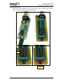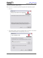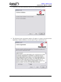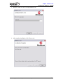
1
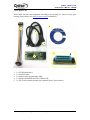
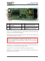
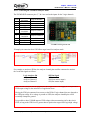
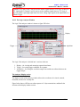
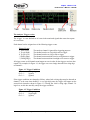
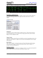
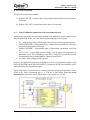
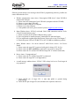
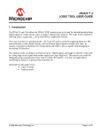
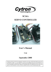
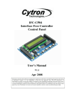
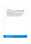
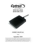
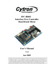
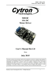
UIC00B
USB ICSP PIC PROGRAMMER
User’s Manual
V1.0
March 2010
Information contained in this publication regarding device applications and the like is intended through suggestion only and may
be superseded by updates. It is your responsibility to ensure that your application meets with your specifications. No
representation or warranty is given and no liability is assumed by Cytron Technologies Incorporated with respect to the accuracy
or use of such information, or infringement of patents or other intellectual property rights arising from such use or otherwise. Use
of Cytron Technologies’s products as critical components in life support systems is not authorized except with express written
approval by Cytron Technologies. No licenses are conveyed, implicitly or otherwise, under any intellectual property rights.
ROBOT . HEAD to TOE
Product User’s Manual – UIC00B
Index
1. Introduction and Overview
1
2. Packing List
2
3. Supported PIC
3
4. Board Layout
5
5. Dimension Drawing
7
6. Installation (hardware)
8
6.1 Using UIC00B with application circuit (development board)
8
6.2 Using UIC00B with UIC-S (optional, buy separately)
10
6.2.1
Plugging the microcontroller
12
7. Installation (software)
15
8. PICkit 2 Programmer
19
8.1
Using PICkit 2 Programmer Software
19
9. PICkit 2 UART Tool
24
9.1
Connecting the PICkit 2 UART Tool
24
9.2
PICkit 2 UART Tool Window
25
9.2.1 ASCII Mode
26
9.2.2 Hex Mode
27
10. PICkit 2 Logic Tool
28
10.1 Logic I/O Mode
28
10.1.1
Configuration the Logic I/O Mode
29
10.1.2
Setting Pin Direction
30
10.2 Analyzer Mode
31
10.2.1
Connecting the UIC00B in Analyzer Mode
31
10.2.2
The Logic Analyzer Window
32
11. Getting Started
36
11.1 Using UIC00B with application circuit (development board)
36
11.2 Using UIC00B with UIC-S (optional, buy separately)
38
12. Troubleshooting
39
13. Warranty (6 months)
40
Created by Cytron Technologies Sdn. Bhd. – All Rights Reserved
0
ROBOT . HEAD to TOE
Product User’s Manual – UIC00B
1. INTRODUCTION AND OVERVIEW
UIC00B is an enhanced version of UIC00A. It offers low cost yet reliable and user friendly
PIC USB programmer solutions for developer, hobbyist as well as students. It is designed to
program popular Flash PIC MCU which includes most of the PIC family. Besides 8bit, it can
also program 16bit and 32bit PIC MCU. On board ICSPTM (In Circuit Serial Programming)
connector offers flexible methods to load program, UART Tool and Logic Tool. It supports
on board programming which eliminate the frustration of plug-in and plug-out of PIC MCU.
This also allow user to quickly program and debug the source code while the target PIC is on
the development board. Since USB port is commonly available and widely used on Laptop
and Desktop PC, UIC00B is designed to be plug and play with USB connection. This
programmer obtained its power directly from USB connection, thus NO external power
supply is required, making it a truly portable programmer. This programmer is ideal for field
and general usage. UIC00B offers reliable, high speed programming and free windows
interface software.
• New! Program most of the +3.3V or +5V PIC.
• New! Compatible with PICkit2’s UART Tool and Logic Tool.
• New! Program most of the current 8-, 16-, and 32-bit Flash PIC microcontroller.
It is designed with capabilities and features of:
• Industrial grade PCB with surface mount component to offer small size yet reliable
and quality product.
• Every component is soldered properly and programmer is tested before it is shipped
to customer.
• USB Plug and Play function.
• IDC box header for ICSPTM connection, an IDC cable is included for external on
board programming.
• Windows XP compatible software.
• Compatible with Windows Vista*.
• Auto load program capability.
• Compatible with Microchip’s PICkit 2.
• Powered directly from USB port.
• NO EXTERNAL POWER REQUIRED for UIC00B to function.
• USB 2.0
• Low cost yet reliable solution.
• Suitable for Laptop and Desktop PC.
• Optional socket (UIC-S) to program 18 pins, 28 pins and 40 pins PIC
microcontroller.
• Dimension 74mm x 28mm
*UIC00B has been tested on several editions of Windows Vista. If user found it is not compatible, we will offer
money back guarantee (need to be shipped back within 3 days from receiving date, shipping is not included).
This document explains the method to use UIC00B.
Created by Cytron Technologies Sdn. Bhd. – All Rights Reserved
1
ROBOT . HEAD to TOE
Product User’s Manual – UIC00B
2. PACKING LIST
Please check the parts and components according to the packing list. If there are any parts
missing, please contact us at [email protected] immediately.
4
3
2
5
1
1.
2.
3.
4.
5.
1 x UIC00B main board
1 x mini USB cable
1 x rainbow cable (programming cable)
1 x Software Installation and User’s Manual CD
1 x UIC-S socket board (optional, buy separately from Cytron website)
Created by Cytron Technologies Sdn. Bhd. – All Rights Reserved
2
ROBOT . HEAD to TOE
Product User’s Manual – UIC00B
3. SUPPORTED PIC
Please refer PICkit 2 Readme file for supported PIC. The file can be downloaded at the
UIC00B product page website.
Created by Cytron Technologies Sdn. Bhd. – All Rights Reserved
3
ROBOT . HEAD to TOE
Product User’s Manual – UIC00B
4. BOARD LAYOUT
A
F
B
C D E
Label
A
B
C
Function
Label
Function
Switch to initiate write device
Target indicator LED (orange)
D
programming
Mini USB port socket
Busy indicator LED (red)
E
Main power supply indicator LED
IDC Box Header for programming
F
(green)
connector
Switch at “A” is a push button which may be used to initiate the write device function when
programmer>Write on PICkit Button is checked.
Mini USB port socket at “B” is for USB connection to PC desktop or laptop. Please connect
the mini header of USB cable to this socket.
Mini USB socket is not designed for frequent plug in and plug out, thus user is advise to
minimize the connect/disconnect of USB cable and Mini USB socket. It is advice to
disconnect it at the other end of USB cable which is USB type A. This will pro-long the
life span of UIC00B.
Green LED at “C” is used to indicate the main power supply of UIC00B. It should ON once
USB connection from UIC00B to computer or laptop is ready.
Orange LED at “D” is used to indicate the UIC00B is powering the target device.
Red LED at “E” is used to indicate busy function such as UIC00B is in program mode or is
alerting that a function is in progress.
Created by Cytron Technologies Sdn. Bhd. – All Rights Reserved
4
ROBOT . HEAD to TOE
Product User’s Manual – UIC00B
IDC box header at “F” is for programming cable. Please connect one end of programming
cable to this header, while the other end to target board.
Figure and table below shown UIC00B pin connection and description.
No Pin
1
2
3
4
5
6
7
8
9
10
UIC00B Pin
Description
Not connect
Not connect
Vpp
GND
ICSP clock/PGC
GND
ICSP data/PGD
VDD
Aux_Out
Not connect
*UIC00B ICSP Programmer Pin
Figure and table below shown SK40C ICSP Programmer pin connection at the target board.
No Pin
1
2
3
4
5
6
7
8
9
10
Target board Pin
Description
Not connect
Not connect
MCLR/Vpp
GND
ICSP clock/PGC
GND
ICSP data/PGD
Not connect
Not connect
Not connect
1 2
3
4
5
6
8
7
9 10
*SK40C target board pin
Created by Cytron Technologies Sdn. Bhd. – All Rights Reserved
5
ROBOT . HEAD to TOE
Product User’s Manual – UIC00B
5. DIMENSION DRAWING
1
Side View
2
Top View
Created by Cytron Technologies Sdn. Bhd. – All Rights Reserved
6
ROBOT . HEAD to TOE
Product User’s Manual – UIC00B
6. INSTALLATION (HARDWARE)
This section will show the connection during UIC00B usage.
6.1 Using UIC00B with application circuit (development board)
1. Connect A-type USB connector (one end of USB cable) to USB port at laptop or PC
desktop.
2. Connect another end of USB cable (mini) to UIC00B USB port.
• Power supply indication green LED will light ON.
3. Continue to software installation if this is the first time usage. Refer to section 6 for
software installation guide.
Created by Cytron Technologies Sdn. Bhd. – All Rights Reserved
7
ROBOT . HEAD to TOE
Product User’s Manual – UIC00B
4. Connect one side of programming cable to box header of UIC00B and the other side
to box header of development board (target device) to be program.
• Use external power for the target board, UIC00B cannot support large power
usage.
Development Board
(Target Device)
UIC00B
To PC or Laptop
USB port
Power supply to
target board
Caution: USB port current limit is 150mA. If the target and UIC00B exceed this current
limit, the UIC00B board might be damaged. The target board should be powered
externally.
Created by Cytron Technologies Sdn. Bhd. – All Rights Reserved
8
ROBOT . HEAD to TOE
Product User’s Manual – UIC00B
6.2 Using UIC00B with UIC-S (optional, buy separately)
1. Connect A-type USB connector (one end of USB cable) to USB port at laptop or PC
desktop.
2. Connect another end of USB cable (mini) to UIC00B USB port.
• Power supply indication green LED will light ON.
3. Continue to software installation if this is the first time usage. Refer to section 6 for
software installation guide.
4. Connect one side of programming cable to box header of UIC00B and the other side
to box header of UIC-S board.
• No external power required for UIC-S to function.
Created by Cytron Technologies Sdn. Bhd. – All Rights Reserved
9
ROBOT . HEAD to TOE
Product User’s Manual – UIC00B
UIC-S
UIC00B
Created by Cytron Technologies Sdn. Bhd. – All Rights Reserved
10
ROBOT . HEAD to TOE
Product User’s Manual – UIC00B
6.2.1
Plugging the microcontroller
40-pin Microcontroller
• Plug in the microcontroller at the ZIF socket and select 40 pins at label “28/40 Pins”
using mini jumper as shown below.
1
2
3
Pin 1
Select to
28/40 pins
Created by Cytron Technologies Sdn. Bhd. – All Rights Reserved
11
ROBOT . HEAD to TOE
Product User’s Manual – UIC00B
28-pin Microcontroller
• Plug in the microcontroller at the upper portion of the ZIF socket and select 28 pins at
label “28/40 Pins” using mini jumper as shown below.
1
3
2
Pin 1
Select to
28/40 pins
Created by Cytron Technologies Sdn. Bhd. – All Rights Reserved
12
ROBOT . HEAD to TOE
Product User’s Manual – UIC00B
18-pin Microcontroller
• Plug in the microcontroller at the lower portion of the ZIF socket and select 18 pins at
label “18 Pins” using mini jumper as shown below.
1
2
3
Pin 1
Select to 18
pins
Created by Cytron Technologies Sdn. Bhd. – All Rights Reserved
13
ROBOT . HEAD to TOE
Product User’s Manual – UIC00B
7. INSTALLATION (SOFTWARE)
Since UIC00B is compatible with PICkit 2, thus PICkit 2 programming software should be
installed. With the help of pictures and some simple instruction, following section will guide
to install the PICkit 2 programming software.
7.1 Install from CD
1. Place UIC00B CD in to computer or laptop CD drive.
2. Browse to folder “UIC00B Setup”.
3. Double click “setup” to run the installation wizard.
7.2 Download setup file from Cytron’s website
1.
User may download the setup file from Cytron’s website:
2.
After finish downloading, unzip the file and click “setup” to run the installation
wizard.
Created by Cytron Technologies Sdn. Bhd. – All Rights Reserved
14
ROBOT . HEAD to TOE
Product User’s Manual – UIC00B
7.3 PICkit 2 Programmer setup procedures
Follow steps below to setup Microchip PICkit2 Programmer after launched the setup file.
1. Click next.
2. The following window concerns the installation folder. Click Browse if you want to
change the default destination. Assuming change, click on Next.
Created by Cytron Technologies Sdn. Bhd. – All Rights Reserved
15
ROBOT . HEAD to TOE
Product User’s Manual – UIC00B
3. Click next to start the installation of the PICkit 2 programming software.
4. The following license agreement window will appears. In order to proceed with the
installation, read the conditions, select the option I Agree and click on Next.
Created by Cytron Technologies Sdn. Bhd. – All Rights Reserved
16
ROBOT . HEAD to TOE
Product User’s Manual – UIC00B
5. Wait for a while. PICkit 2 is being installed to PC.
6. After complete installation, click Close to exit.
Created by Cytron Technologies Sdn. Bhd. – All Rights Reserved
17
ROBOT . HEAD to TOE
Product User’s Manual – UIC00B
8. PICkit 2 Programmer
8.1 Using PICkit 2 Programmer
After installing hardware and software in previous section, UIC00B is ready to be used with
PICkit 2 programming software. This section gives instruction on how to get started with
UIC00B. With the help of pictures and some simple instruction, following section illustrates
the steps using UIC00B.
1. Connect the UIC00B as shown in section 5 (hardware installation).
2. Launch PICkit 2 programming software by selecting Start> Program> Microchip>
PICkit 2.
• The following programming interface appears and notifies that the PICkit 2 and
target device found and connected.
• This programmer is able to automatically detect PIC from connected target and
display it in the Device Configuration window.
Created by Cytron Technologies Sdn. Bhd. – All Rights Reserved
18
ROBOT . HEAD to TOE
Product User’s Manual – UIC00B
•
If PICkit 2 Programmer does not detect the PIC automatically, user needs to help
PICkit 2 Programmer to detect it manually. Click Tools and then Check
Communication. PICkit 2 Programmer will detect the device and name it.
•
If device is successfully detected, the device name will appeared at “Device
Configuration” area.
3. UIC00B can supply power to the target device for PIC MCU. If users are going to
power the target board from the UIC00B, do not attach a power supply to the target
board. To supply power to the target device, click checkbox “On”. The voltage may
be set in the box on the right either by typing it directly or using the up/down arrows
to adjust it a tenth of a volt at a time. The maximum and minimum allowed voltages
will vary depending on the target device. If the “On” checkbox is unchecked, PICkit 2
will automatically turn on the VDD at the set voltage during any requested
programming operation. Please make sure the VDD of the target device is connected
to the programmer if user would like to use this features.
4. Although UIC00B can supply power to PIC on the target device, users are advised to
power the target device externally to prevent this programmer exceed from 150mA
current limit. If the target device has its own power supply, then the PICkit 2 will
display the detected VDD voltage in the box on the right, which will be grayed out to
prevent being changed.
Created by Cytron Technologies Sdn. Bhd. – All Rights Reserved
19
ROBOT . HEAD to TOE
Product User’s Manual – UIC00B
Caution: USB port current limit is 150mA. If the target and UIC00B exceed this current
limit, the UIC00B board might be damaged. The target board should be powered
externally. If the target device is powered externally, please DONOT connect VDD (5V)
of UIC00B to target PIC, only one power supply should be connected to target PIC.
5. Import the Hex file by choosing ‘File’ and click ‘Import Hex’.
6. Browse for the hex file and click Open. The code is displayed in the Program Memory
and EEPROM Data windows. The name of the hex file is displayed in the Source
Block under Program Memory. Hex file generated from MPLAB IDE will be named
according to project name, not C file name.
7. After a device family has been selected and a hex file has been imported, the target
device can be programmed by clicking Write. The device will be erased and
programmed with the hex code previously imported.
Created by Cytron Technologies Sdn. Bhd. – All Rights Reserved
20
ROBOT . HEAD to TOE
Product User’s Manual – UIC00B
8. The status of the write operation is displayed in the status bar located under the device
Configuration window. If the write is successful, the status bar turns green and
displays “Programming Successful” as shown in figure below.
9. User may automatically reload hex file using push button (on UIC00B main board).
Push button can be used after Programmer>Write on PICkit Button is checked as
figure below:
10. Push button allow user to reload the updated hex file into the target device. After
convert any changes in the program into Hex file, press push button and UIC00B will
automatically reload the new Hex file, further program into the target device.
11. Verify function verify the device program to the imported Hex file. Read function is to
view the code written to the PIC. The code will be display in the Program Memory
and Data EEPROM Memory. If all zero display, it is possible that the target device is
code-protected. Erase button erases the program memory, data EEPROM memory, ID
and Configuration bits, regardless of the state of the Program Memory and EEPROM
Data “Enabled” checkboxes. Blank Check button will read the entire device to
Created by Cytron Technologies Sdn. Bhd. – All Rights Reserved
21
ROBOT . HEAD to TOE
Product User’s Manual – UIC00B
determine if Program Memory, EEPROM Data Memory, User Id and Configuration
bits are erased.
12. Auto Import Hex + Write Device allows the programmer to automatically import and
write the Hex file to the connected device when the Hex file is updated, for an
example on a new firmware build. By clicking this icon, it will bring up an Import
Hex File dialog. Read Device + Export Hex File Button will read the target device
and open an Export Hex File dialog.
13. After selecting file, Hex code will be written to the target device and UIC00B will
monitor the selected file for update. If the file is updated (after compiled), UIC00B
will automatically re-imports the Hex file and writes to the target device. To disable
this feature, simply click this icon again.
Created by Cytron Technologies Sdn. Bhd. – All Rights Reserved
22
ROBOT . HEAD to TOE
Product User’s Manual – UIC00B
9. PICkit 2 UART TOOL
PICkit 2 UART Tool used as a serial UART terminal interface for communication
with a PIC microcontroller. The features of PICkit 2 UART Tools are:
•
•
•
•
9.1
Displaying debug text output from microcontroller.
Logging microcontroller data to a text file
Developing and debugging a microcontroller UART interface
Interfacing with and sending commands to the microcontroller during
development.
Connecting the PICkit 2 UART Tool
UIC00B connects to the target board as shown in figure below. The UIC00B Tx signal (out)
should connect to the target Rx signal (in), and the UIC00B Rx signal (in) should connect to
the target Tx signal (out).
No Pin
UIC00B Pin
Description
Connection to
Target board
1
2
3
4
5
6
7
8
9
10
Not connect
Not connect
Not connect
GND
Tx
GND
Rx
VDD
Not connect
Not connect
GND
Rx
GND
Tx
VDD
-
1 2
3 4
5 6
7 8
9 10
*UIC00B ICSP Programmer Pin
*Example pin connection from UIC00B to target board for UART Logic Tool.
Created by Cytron Technologies Sdn. Bhd. – All Rights Reserved
23
ROBOT . HEAD to TOE
Product User’s Manual – UIC00B
When using PICkit UART Tool, UIC00B may not be able to supply VDD voltage to the
target board depending on the application version. However, even when UIC00B not
supplying the target VDD, the UIC00B VDD must be connected to the target VDD voltage or
it will not be able to communicate.
The UIC00B will supply target VDD from 3.3V to 5V.
9.2 PICkit 2 UART Tool Window
To start with PICkit 2 UART Tool, select Tools> UART Tool… The PICkit 2 Programmer
cannot be used while the UART Tool is active. The PICkit 2 UART Tool Window shown as
figure below.
Created by Cytron Technologies Sdn. Bhd. – All Rights Reserved
24
ROBOT . HEAD to TOE
Product User’s Manual – UIC00B
The UART Tool has 2 modes which are ASCII and HEX. The mode buttons are on the upper
right hand of the display. The mode selection affects how serial data is displayed and entered
in the window.
The baudrate may be selected from the combo box in the upper left corner of the UART Tool
window. The baudrate can be used is between 150 to 38400.
Click Connect to enable the UART Tool serial interface at the selected baud. Click
Disconnect to disabled connection.
9.2.1
ASCII Mode
When ASCII mode is selected, serial bytes received from the target’s UART are displayed as
ASCII characters in the main window terminal display.
Bytes may be transmitted in three ways:
•
Click on the terminal display to select it. Any characters typed on the PC keyboard
will be immediately transmitted out of PICkit 2.
•
Right click on the terminal display and select Paste from the pop-up menu to paste
any previous copied or cut text. Any pasted data will immediately be transmitted out
of PICkit 2.
•
Use the “String Macros” at the bottom of the window. The “String Macros” allow up
to four strings of characters to be entered. Each string can be up to 60 characters long.
Data Transmitted
Created by Cytron Technologies Sdn. Bhd. – All Rights Reserved
Data Received
25
ROBOT . HEAD to TOE
Product User’s Manual – UIC00B
9.2.2
Hex Mode
The UART Tool Hex mode displays the hex values of bytes received from the target’s UART
in the terminal display.
A line of bytes received by the UART Tool is preceded with the “Rx:” and a line of bytes
transmitted by the UART Tool is preceded with the text “Tx:”. From Figure above, the four
hex bytes 0x50, 0x4B, 0x53 and 0x41 were received from the target. The three bytes 0x70,
0x6B and 0x32 were then transmitted.
In the hex mode, bytes may only be transmitted one way: by typing a sequence of one or
more hex values in one of the four “Send Hex Sequences:” boxes. To send a sequence, click
Send next to it. A hex sequence may contain from 1 to 48 bytes.
Created by Cytron Technologies Sdn. Bhd. – All Rights Reserved
26
ROBOT . HEAD to TOE
Product User’s Manual – UIC00B
10. PICkit 2 LOGIC TOOL
The PICkit 2 Logic Tool will be use UIC00B ICSPTM (In Circuit Serial Programming)
connector pins for stimulating and probing digital signals on a target circuit, and as a simple 3
channel logic analyzer. They are 2 logic modes in PICkit 2 Logic Tool which are
•
•
Logic I/O mode
Analyzer mode
To open PICkit 2 Logic Tool, select Tools> Logic Tool
10.1 Logic I/O Mode
The Logic I/O mode is useful for triggering inputs to a PIC microcontroller or other digital
circuitry, and monitor digital signals to display their state.
No
Pin
Pin Description
Logic I/O Function
8
Not connect
Not connect
Vpp
GND
ICSP
Clock/PGC
GND
ICSP
Data/PGD
VDD
9
Aux_Out
10
Not connect
Digital Output
GND
Digital Output or
Digital Input
GND
Digital Output or
Digital Input
VDD
Digital Output or
Digital Input
-
1
2
3
4
5
6
7
1 2
3 4
5 6
7 8
9 10
*UIC00B ICSP Programmer Pin
Created by Cytron Technologies Sdn. Bhd. – All Rights Reserved
27
ROBOT . HEAD to TOE
Product User’s Manual – UIC00B
*Example pin connection from UIC00B to target board for Logic I/O mode
UIC00B pin must be connected to the target circuit VDD supply. The voltage level at the
VDD pin sets the output high voltage for pins 5, 7, & 9 when used as outputs. For example, if
using the PICkit 2 to provide digital stimulus to a 3.3V circuit, the VDD pin should be either
set to or connected to a 3.3V supply to limit the output high voltage to 3.3V.
Pin 3’s output voltage swing is determined by the voltage on the VDD pin when the Logic
I/O is first enabled.
When used as inputs, pins 5 & 7 may be used to monitor signals down to 2.5V logic, as these
are TTL input buffers. Pin 9 as an input may be used to monitor signals down to 3.6VLogic.
It may not reliably report high signal states for lower voltage logic signals as the input buffer
is a Schmitt Trigger.
10.1.1 Configuring the Logic Tool Logic I/O
The PICkit 2 Logic Tool “Logic I/O” mode is the default mode when the Logic Tool is first
opened.
Logic I/O shown in figure above is different with UIC00B pin used for Logic I/O.
UIC00B use pin 3, 5, 7 and 9 for Logic I/O. Please refer table on chapter 9.1 for Logic I/O
pins.
Created by Cytron Technologies Sdn. Bhd. – All Rights Reserved
28
ROBOT . HEAD to TOE
Product User’s Manual – UIC00B
Click Enabled IO button to activate the UIC00B pins used for Logic I/O digital signals (pins
3, 5, 7, & 9). After the IO is enabled, user may configure it. If no valid voltage is detected on
the VDD pin when clicking Enabled IO a dialog will pop up to alert the user.
10.1.2 Setting Pin Direction
Now that the I/O pins are enabled, the pin directions and output states can be configured.
Logic I/O shown in figure above is different with UIC00B pin used for Logic I/O.
UIC00B use pin 3, 5, 7 and 9 for Logic I/O. Please refer table on chapter 9.1 for Logic
I/O pins.
Pins 5, 7, & 9 may be configured as Outputs (output a digital signal from UIC00B) or Inputs
(monitor a digital signal state connected to the pin). Pin 3 is only available as an output.
Click the radio buttons next to the Pin# to set the pin as an Output or Input. When the pin is
an Input, the connected signal state is displayed in the blue “Inputs” box as shown in Figure
below.
Logic I/O Input Signal is Logic Low (0)
Created by Cytron Technologies Sdn. Bhd. – All Rights Reserved
29
ROBOT . HEAD to TOE
Product User’s Manual – UIC00B
Logic I/O Input Signal is Logic High (1)
Pin 5 and pin 7 have a 4.7K Ohm pull down resistor internal to the UIC00B. This resistor is
necessary for the PICkit 2 debugger functions, but note that this pull down resistor will
affect any digital signal it is connected to. Generally, it is only an issue when using Pin 5
and pin 7 as an input.
When a pin is selected as an Output, the pin will drive the logic level shown in the read
“outputs” box. Toggle the output state by clicking on the Output state box.
Logic I/O Input Signal is Logic Low (0)
Logic I/O Input Signal is Logic High (1)
10.2
Logic Analyzer Mode
The Analyzer mode of the PICkit 2 Logic Tool enables using UIC00B as a simple channel
logic analyzer to capture, view and measure the digital waveforms of up to 3 signals.
Created by Cytron Technologies Sdn. Bhd. – All Rights Reserved
30
ROBOT . HEAD to TOE
Product User’s Manual – UIC00B
10.2.1 Connecting the UIC00B in Analyzer Mode
The UIC00B ISCP connector pins 5, 7, & 9 are used as the inputs for the 3 logic channels.
No Pin
1
2
3
4
5
6
7
8
9
10
Pin
Description
Not connect
Not connect
Vpp
GND
ICSP
Clock/PGC
GND
ICSP
Data/PGD
VDD
Aux_Out
Not connect
Logic I/O Function
GND
Analyzer Channel 1
GND
Analyzer Channel 2
1 2
3 4
5 6
7 8
9 1
VDD
Analyzer Channel 3
*UIC00B ICSP Programmer Pin
*Example pin connection from UIC00B to target board for Analyzer mode
For example, to monitor a SPI bus, the analyzer channel pins could be connected to monitor
the 3 main bus signals as follows:
Logic Analyzer Pin
Analyzer Channel 1
Analyzer Channel 2
Analyzer Channel 3
SPI Bus Signal
SCK
SDO (bus master output)
SDI (bus master input)
The UIC00B VDD pin must be connected to the target circuit VDD supply or set to provide a
VDD output voltage in the main PICkit 2 application form.
Having the VDD pin connected is necessary as the PICkit 2 logic channel pins are clamped to
the VDD pin voltage. If no voltage is present on VDD, the analyzer channel pins will be
essentially clamped to ground.
It is possible to have UIC00B output a VDD voltage without connecting pin2 to the circuit
VDD, as long as the VDD level is greater than or equal to the target circuit logic high voltage.
Created by Cytron Technologies Sdn. Bhd. – All Rights Reserved
31
ROBOT . HEAD to TOE
Product User’s Manual – UIC00B
Channels 1 & 2 (pins 5 and 7) may be used to monitor signals down to 2.5V logic, as these are
TTL input buffers. Channel 3 (pin 9) may be used to monitor signals down to 3.6V logic. It
may not reliably report high signal states for lower voltage logic signals as the input buffer is a
Schmitt Trigger.
10.2.2 The Logic Analyzer Window
The Logic Tool analyzer window is shown as figure XX below.
1
Display
2
3
Aquisition
Trigger
The Logic Tool analyzer is divided into 3 sections which are
1. Display – for viewing and measuring captured waveforms.
2. Trigger – for setting trigger conditions for a capture.
3. Acquisition – for setting the waveform sample rate and the waveform relation to the
trigger sample.
The Analyzer Display section
The display section of the analyzer window allows the waveform to be viewed, zoomed,
measured, and saved as a bitmap file.
Figure below shows a SPI bus waveform capture of a 2-byte transmission, and details the
elements of the display window section.
Created by Cytron Technologies Sdn. Bhd. – All Rights Reserved
32
ROBOT . HEAD to TOE
Product User’s Manual – UIC00B
The Analyzer Trigger section
The “trigger” is a user-defined set of events in the monitored signals that causes the capture
of a waveform.
Each channel can be assigned one of the following trigger events:
Trigger Events
‘*’ (Don’t care)
‘1’ (Logic High)
‘0’ (Logic Low)
‘/’ (Rising Edge)
‘\’ (Falling Edge)
The analyzer channel is ignored for triggering purposes
The channel must be at a logic high state to trigger
The channel must be at a logic state to trigger
The channel must transition from low to high states to trigger
The channel must transition from high to low states to trigger
All trigger events on all channels must happen at once in order for the trigger to activate data
capture. For example, for Figure 1-1, the rigger was set to simply detect the first rising edge
on channel 1:
Figure 1-1 Trigger Conditions
Ch 1 = /
(rising edge)
Ch 2 = *
(ignore)
Ch 3 = *
(ignore)
If the trigger conditions are changed as follows, where both a rising edge must be detected on
channel 1 at the same time channel 2 is at a logic high state, the trigger will happen on the
second clock instead as shown in Figure 1-2. During first clock’s rising edge, channel 2 is
logic low, so this does not fully satisfy the trigger condition.
Figure 1-2 Trigger Conditions
Ch 1 = /
(rising edge)
Ch 2 = 1
(logic high)
Ch 3 = *
(ignore)
Created by Cytron Technologies Sdn. Bhd. – All Rights Reserved
33
ROBOT . HEAD to TOE
Product User’s Manual – UIC00B
Figure 1-2 Trigger Ch 1 Rising Edge when Ch 2 is high
The Analyzer Acquisition Section
The “Acquisition” section of the analyzer window is used to set the waveform sample rate,
the position of the trigger relative to the captured waveform, and to start or “run” the
analyzer.
Acquisition Settings
Sample Rate
The sample rate is how often the analyzer channels are look at. Each waveform capture is
only 1024 samples long, so if we want to look at a longer period of time in the waveform
display, we have to sample less often.
Trigger Position
Changing the trigger position allows more flexibility over how the captured data relates to the
trigger event. For example, we might be more interested in what happened before the trigger,
rather than after.
Delay Window
When “Delay 1 window” is selected, the analyzer will wait 1000 samples after the trigger
event occurs before it begins recording waveform data. When “Delay 2 Windows” is
selected, it will wait 2000 samples etc.
Running the Analyzer
Once the trigger conditions, sample rate, and trigger position are set as desired click the RUN
button to begin collection waveform data and looking for trigger events.
Created by Cytron Technologies Sdn. Bhd. – All Rights Reserved
34
ROBOT . HEAD to TOE
Product User’s Manual – UIC00B
When the analyzer is running, it will show the dialog in figure below.
Created by Cytron Technologies Sdn. Bhd. – All Rights Reserved
35
ROBOT . HEAD to TOE
Product User’s Manual – UIC00B
11. GETTING STARTED
UIC00B can be used in two methods:
1) Program a PIC MCU with the MCU on development board which has been shown in
section 6.1.
2) Program a PIC MCU in stand alone mode, shown in section 6.2.
11.1
Using UIC00B with application circuit (development board)
UIC00B can program PIC microcontroller installed in the application circuit using In-Circuit
Serial Programming (ICSP). In-Circuit Serial Programming requires five signals:
•
•
•
•
•
VPP – Programming voltage. When applied, the device goes into programming mode.
ICSPCLK/PGC/RB6 – Programming clock; a unidirectional synchronous serial clock
line from the programmer to the target.
ICSPDAT/PGD/RB7 – Programming data; a bidirectional synchronous serial data
line.
VDD (3.3V/5V) – Power supply positive voltage, it can be either from programmer or
application circuit. This is optional to target PIC. If target PIC is powered externally
(recommended) this pin should NOT be connected to target PIC.
VSS (Gnd) – Power supply ground reference.
However, the application circuit must be designed to allow all programming signals (Vpp,
ICSPCLK/PGC/RB6 and ICSPDAT/PGD/RB7) to connect to the PIC microcontroller device
without distorting the programming signals.
Figure below shows a typical circuit as a starting point when designing an application circuit
for the ICSP. Those unconnected pins (1, 2, 9 & 10) of Box header should be leaved
unconnected on application circuit. Figure below is the example for +5V PIC:
Created by Cytron Technologies Sdn. Bhd. – All Rights Reserved
36
ROBOT . HEAD to TOE
Product User’s Manual – UIC00B
Note: PIC microcontroller in the figure above is for reference purpose only. Refer to
PICkit 2 Readme for supported PIC models.
Please be aware of:
•
During programming mode, it is recommended to isolate the supervisory circuit if
interfaces with MCLR pin by using Schottky-type diode or high switching diode
(1N4148) to prevent VPP voltage slew rate from slow down and exceeds the rise time
in the programming specification (typically 1µs). There should not be capacitive
component (capacitor) connected to MCLR directly.
•
RB7/PGD or RB6/PGC pin are recommended to use as output controlling non critical
device such as LED, LCD, 7 segments or buzzer. It is recommended to isolated ICSP
signals from application circuit by using series resistor (range 220 ohm and above) as
shown in figure above. Furthermore, NO capacitive component (capacitor) should be
connected to these 2 pins directly.
•
During ICSP programming, PIC microcontroller needs to be powered. It is
recommended to power the target externally; USB is not able to support large power
usage. If target PIC is powered externally VDD (3.3V/5V) should NOT be connected
to target PIC.
•
The minimum connections from UIC00B to target board or PIC are four. These
include Vpp, PGD, PGC and Vss (Gnd).
•
Thus, the 3.3V/5V from UIC00B is an optional connection. If user is powering up
the target board with external power, this pin is not necessary to connect from
UIC00B to target board.
•
For usage example, please refer to DIY Project (PR7 onwards) in Cytron website.
Created by Cytron Technologies Sdn. Bhd. – All Rights Reserved
37
ROBOT . HEAD to TOE
Product User’s Manual – UIC00B
11.2
Using UIC00B with UIC-S (optional, buy separately)
UIC-S is an optional socket that can be used with UIC00B to program several types of PIC
microcontroller. Below are the steps of using the UIC-S and method to connect it to UIC00B:
1. Connect one side of the rainbow cable (programming cable) to box header of
UIC00B board and the other side to box header of UIC-S as shown in section6.2.
Power LED will not turn on at this time.
2. After that, use mini jumper (on UIC-S) to select either 18 pins or 28/40 pins
(according to the PIC microcontroller that you want to program).
3. Load the hex file as shown in section 8. LED PWR of UIC-S will ON (once user
click write button to load the hex file) indicate that the board is working correctly.
Created by Cytron Technologies Sdn. Bhd. – All Rights Reserved
38
ROBOT . HEAD to TOE
Product User’s Manual – UIC00B
11. TROUBLESHOOTING
Following section discuss error messages from PICkit 2 programming software, possible root
causes and methods to fix it.
a. Window (right bottom corner) show “Unrecognized USB device” when UIC00B is
connected to USB port.
i) Please check the connection of your USB cable (computer and also UIC00B).
ii) Please try to use other USB cable.
iii) Please try other USB port on computer.
iv) Please try on other computer.
v) If the problem still occur, please contact Cytron at [email protected]
b. Status Window shows: “PICkit 2 not found. Check USB connections and use Tools>Check Communication to retry”.
i) Please reconnect the UIC00B to USB port and try again.
ii) Driver might not be installed properly, uninstall driver and install again.
iii) User might need to update Operating System. Please refer to step 14 of chapter 7.
iv) Check the power LED on UIC00B. If it is Off, UIC00B have hardware problem.
c. Status Window shows: “No device detected” while Device shows: “No Device
Found”.
i) Please ensure the target PIC is powered with typical voltage of 5V for Vcc.
ii) Please ensure the PGC and PCD is connected to correct pin on target PIC.
iii) Please ensure the Vss (Gnd) of UIC00B and target PIC is common (connected).
d. Device shows: “Unsupported part”.
i) Please ensure the Vss (Gnd) of target PIC is connected.
ii) Please ensure the target PIC is in supported list.
e. A small message window shows: “PICkit 2 VPP voltage level error. Check target &
retry operation”.
i) Check MCLR pin of target PIC, it must not pulled to ground during
programming.
ii) Check MCLR pin of target PIC, there should not be capacitor connected.
Created by Cytron Technologies Sdn. Bhd. – All Rights Reserved
39
ROBOT . HEAD to TOE
Product User’s Manual – UIC00B
For any feedbacks and inquiries, please send an email to [email protected]
12. WARRANTY
Product warranty is valid for 6 months.
Warranty only applies to manufacturing defect.
Damage caused by misuse is not covered under warranty.
Warranty does not cover freight cost for both ways.
Prepared by
Cytron Technologies Sdn. Bhd.
19, Jalan Kebudayaan 1A,
Taman Universiti,
81300 Skudai,
Johor, Malaysia.
Tel:
Fax:
+607-521 3178
+607-521 1861
URL: www.cytron.com.my
Email: [email protected]
[email protected]
Created by Cytron Technologies Sdn. Bhd. – All Rights Reserved
40