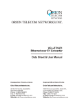
1
UHF FM DIGITAL TRANSCEIVER ST-1000D ST-1000C VHF FM DIGITAL TRANSCEIVER ST-1000V SmarTrunk Systems, INC. ST-1000UM R1.0a Printed in Malaysia PN: AL1000010A FCC NOTICE This device complies with Part 15 of the FCC Rules. Operation is subject to the following two conditions: (1) This device may not cause harmful interference, (2) This device must accept any interference received, including interference that may cause undesired operation. FEDERAL COMMUNICATIONS COMMISSION INTERFERENCE STATEMENT This equipment has been tested and found to comply with the limits for a Class B digital device, pursuant to Part 15 of the FCC Rules. These limits are designed to provide reasonable protection against harmful interference in a residential installation. This equipment generates, uses and can radiate radio frequency energy and, if not installed and used in accordance with the instructions, may cause harmful interference to radio communications. However, there is no guarantee that interference will not occur in a particular installation. If this equipment does cause harmful interference to radio or television reception, which can be determined by turning the equipment off and on, the user is encouraged to try to correct the interference by one or more of the following measures: --Reorient or relocate the receiving antenna. --Increase the separation between the equipment and receiver. --Connect the equipment into an outlet on a circuit different from that to which the receiver is connected. --Consult the dealer or an experienced radio/TV technician for help. Page 2 THANK YOU! We are grateful you chose SmarTrunk for your land mobile radio applications. We believe this powerful, flexible and easy-to-use transceiver will provide dependable and reliable communications to keep personnel operating at peak efficiency. SmarTrunk transceivers incorporate the latest in advanced SDR technology. As a result, we feel strongly that you will be pleased with the quality and features of this product. NOTICES TO THE USER GOVERNMENT LAW PROHIBITS THE OPERATION OF UNLICENSED RADIO TRANSMITTERS WITHIN THE TERRITORIES UNDER GOVERNMENT CONTROL. ILLEGAL OPERATION IS PUNISHABLE BY FINE, IMPRISONMENT, OR BOTH. REFER SERVICE TO QUALIFIED TECHNICIANS ONLY. SAFETY: It is important that the operator is aware of and understands hazards common to the operation of any transceiver. WARNING: EXPLOSIVE ATMOSPHERES (GASES, DUST, FUMES, etc.) Turn off your transceiver while taking on fuel, or while parked in gasoline service stations. Page 3 ATTENTION (U.S.A. Only): The RBRC Recycle seal found on Smartrunk lithium-ion (LiIon) battery packs indicates Smartrunk‘s voluntary participation in an industry program to collect and recycle Li-Io batteries after their operating life has expired. The RBRC program is an alternative to disposing Li-Io batteries with your regular refuse or in municipal waste streams, which is illegal in some areas. For information on Li-Ion battery recycling in your area, call (toll free) 1-800-8-BATTERY (1-800-822-8837). Smartrunk’s involvement in this program is part of our commitment to preserve our environment and conserve our natural resources. PRECAUTIONS Observe the following precautions to prevent fire, personal injury, and transceiver damage. - Do not modify this transceiver for any reason. - Do not expose the transceiver to long periods of direct sunlight, nor place it close to heating appliances. - Do not place the transceiver in excessively dusty, humid, and/or wet areas, or on unstable surfaces. - If an abnormal odor or smoke is detected coming from the transceiver, switch OFF the power immediately and remove the optional battery pack from the transceiver. Contact your SmarTrunk dealer. Page 4 CONTENTS Contents Page APPENDIX I: DEALER PROGRAMMED FUNCTIONS ….19 BATTERY CHARGER....................................................................... 9 GETTING ACQUAINTED .............................................................. 13 Installing the Antenna ST-FA0X ................................................. 12 Installing the Belt Clip ................................................................ 12 Installing/ Removing the LI-Ion Battery Pack ........................... 12 LED INDICATOR ........................................................................... 16 MAKING A CALL .......................................................................... 14 PROGRAMMABLE BUTTONS FUNCTIONS ................................. 16 ROTARY FUNCTIONS .................................................................. 15 SMARTRUNK ST-SBP18 ................................................................ 7 SWITCH ON/OFF AND VOLUME SELECTOR .............................. 16 UNPACKING AND CHECKING EQUIPMENT ................................. 6 Page 5 UNPACKING AND CHECKING EQUIPMENT Note: The following unpacking instructions are for use by your SmarTrunk dealer, an authorized SmarTrunk service facility, or the factory. Carefully unpack the transceiver. We recommend that you identify the items listed in the following table before discarding the packing material. If any items are missing, or have been damaged during shipment, file a claim with the carrier immediately. Supplied Accessories Item Battery pack Part number Quantity ST-B16 1 ST-BH02 1 Screw set ST-1000BCS 1 Instruction manual ST-1000UM 1 Smartrunk ST-1000 Transceiver ST-1000X 1 Desktop Battery Charger ST-BC-02 1 AC Power adaptor ST-AC02 1 Antenna ST-FAC02 1 Belt clip Before to start, you must read carefully about the battery and the battery charger operation, then assembly the radio as per the instructions bellow. Page 6 SMARTRUNK ST-B16 BATTERY PACK RECOMMENDATIONS If not charged or used correctly, Lithium Polymer batteries may ignite without warning and cause serious injury and property damage. If you are unable to follow the safety recommendations then do not use them Do not charge Lithium Polymer cells on or near combustible materials including paper, plastic, carpets, vinyl, leather, or wood. Do not charge inside an automobile. Do not forcefully discharge the Lithium Polymer battery. Doing so will damage the pack. Never exceed the charge or discharge current rating. Do not expose Lithium Polymer cells to water or moisture at any time. Do not store or use Lithium Polymer batteries near an open flame or heater. Never use a Lithium Polymer battery that may have been subjected to damage or harsh handling. Carefully inspect the Page 7 battery and connectors for even the smallest damage. CAUTION: cells may be hot! Do not allow the electrolyte to get into eyes or on skin. Wash affected areas immediately if get in contact with electrolyte. Do not alter or modify connectors or wires of a Lithium Polymer battery pack. NEVER incinerate used batteries. This may cause an explosion. NEVER use the charger when it is covered by objects which impede heat dispersal. Make sure battery and charger contacts are always clean; otherwise batteries may not fully charge. Lithium Polymer batteries are different from Ni-Cd batteries in that it is not necessary to completely charge and discharge them to extend the battery life. Therefore, charging the battery when the remaining charge is under 10% and keep charging up to the battery reaches 90% is recommended to extend the battery life. If your batteries seem to have no capacity even after being fully charged, charge them again. If it do not retain a charge (or very little), new batteries must be purchased. Page 8 SMARTRUNK BC-02 BATTERY CHARGER Never leave the charger unattended. If you will be away from the charger then leave it unconnected from the battery. Charge all batteries on concrete, at least 10 feet (3 meters) away from combustible materials. Do not use if flammable liquids are in the area. Use this charger only with SmarTrunk Lithium Polymer battery packs. No other battery chemistry can be used. Do not charge a battery if it is hot. Allow them to cool first. AVOID charging in conditions of extreme cold (under 0°C; +32°F) or extreme heat (over +45°C; +113°F). Batteries may not charge under extreme temperatures. Do not charge any battery that appears to be swollen or damaged in any way. Do not disassemble the charger in any way. This is dangerous and will void the warranty. NEVER let metal, wire, etc. touch any internal part of the charger. Keep the charger away from children and animals. USE INDOORS ONLY! NEVER expose the charger to rain, snow or any liquids. NEVER insert battery pack/transceiver (with the battery pack attached) in a wet or soiled condition into the charger. This may result in corrosion of the charger terminals or damage to the charger. The charger is not waterproof and water can easily get into it. Page 9 The Battery Charger ST-BC02 is a device specially designed to recharge SBP-16 battery pack compatible with ST-1000 SDR radio. This device has enough internal intelligence to exchange information with the battery under charge and improves charging regulation to extend battery life as much as possible, keeping risk out of battery damage by wrong recharging process. Operation: Load the battery pack ST-B16 alone using the battery guides or just insert the complete radio ST-1000 with the battery on it. As soon as you load the battery, Charge LED will let you know the charging process has started (continuous red light). Page 10 End of charge: As soon as the re-charge process has been completed the charger led becomes green. You can decide when the performance becomes too poor to buy a new battery, but anyway, the battery life indicator will let you get an approximate idea of battery health after the charging process ends. Charging Failure: ST-BC-02 gets information from the battery pack continously when connected to the battery. All parameters are controlled; the charging voltage, temperature and current are continuosly controlled on real time. If any of the parameters becomes out of normal status, the battery charger will abort the process, then chargers LED will blink on red as an idication of charging failure. In case of failure, please remove the battery from the charger then wait few minutes before trying again. Sometime, the charging temperature is too high, or in case the radio is powered on, perhaps it demands too high current enlarging too much the target time to end the charging process. Battery failure indication will also appears if the battery elements are damaged or too aged. Depending on the DC input voltage and the temperature, a complete process will demand between 3 and 4 hours. If the radio is on during the charging process, the time will extend, depending on the radio activity. Page 11 Installing/ Removing the LI-Ion Battery Pack Only use the ST-B16 battery packs with this transceiver. To install the battery, please complete the following steps. 123- Match the grooves of the battery pack with the corresponding holes on the back of the transceiver. Pull the battery pack down on the back of the transceiver until the release latch on the base of the battery locks. To remove the battery pack, pull off the battery lock and pull the pack away from the transceiver. Installing the Antenna Screw the antenna into the connector on the top of the transceiver by holding the antenna at its base and turning it clockwise until secure. Installing the Belt Clip If desired, attach the belt clip using the two supplied screws. Note: If the belt clip is not installed, its mounting location may get hot during continuous transmission or when left sitting in a hot environment. Page 12 GETTING ACQUAINTED 8 1 2 3 7 4 6 5 1. Rotary encoder Move clockwise or counterclockwise to change the selection according to the mode programmed for this encoder. 2. Power switch and Volume control Turn clockwise to switch ON the transceiver. Rotate to adjust the volume. Turn fully counterclockwise to switch OFF the transceiver Page 13 3. Transmit/ Busy/ Low Bat Lights red during transmission Green while receiving a call Blinks on red to show low battery status 4. Speaker 5. Microphone 6. Side Keys Press to activate its programmable function. The function assigned to this key is designed by your dealer. 7. PTT (Push-to-Talk) switch Press this switch, and then speak into the microphone to call a station. 8. Antenna MAKING A CALL To place a call to other party or group, please follow the steps: Press the PTT switch and speak into the microphone in your normal speaking voice. For best sound quality at the receiving station, hold the microphone approximately 1.5 inches (3-4 cm) from your mouth. Release the PTT switch to receive. Adjust the volume level as per your desire when receiving. Page 14 If enabled by your radio programmer or dealer, your radio may have a time out timer, which can set a limit to the max length of your transmission without releasing the PTT. If it happens, you will receive a warning beep. ROTARY FUNCTIONS Top rotary switch function can be assigned to different associated functions in your dealer shop. Please check with your dealer the function assigned to this knob. Possible functions are: None: Moving this selector do not generate any operation. Channel Selector: Select current channel to operate the radio. Contact selection: If enabled, you can select one of 16th destinations for your call operating on digital mode. If the rotary is in in a non-programmed position, it will warn the user with an error tone. LED INDICATOR A tri-color led indicator has been added on your radio to visual communicate the following status. Lights red: while transmitting. Page 15 Lights green: while receiving. Flashes red: when the battery power is low, once per 2 second when battery charge is under the 5% and once per second when it’s less than 2%. SWITCH ON/OFF AND VOLUME SELECTOR Turn clockwise to switch ON the transceiver. Rotate to adjust the volume. To switch OFF the transceiver, turn it counterclockwise fully. PROGRAMMABLE BUTTONS FUNCTIONS Each one of the side buttons can be programed, as you want. There are many possibilities for each key, regarding the long or short push. The functions to each key are assigned for your dealer on programming time. Functions of your keyboard are pre-assigned by your dealer or programmer. Please check the assigned function table already programmed into your radio. Some functions may not be active in your programming. Channel Up: Selects the next channel in the current channel list from current bank. If the rotary is also set for channel selector, this button action will still change the channel, overriding the top rotary switch Page 16 position. If your radio is in the end of the list, it will jump to the first channel in your channel table (roll over) Channel Down: Selects the previous channel in the current channel list from current bank. If the rotary is also set for channel selector, this button action will still change the channel, overriding the top rotary switch position. If your radio is in the first channel of the list, it will jump to the last channel in your channel table (roll over) Power Toogle: Change the radio transmitting power. Possible values, High/Low. The power associated to High, Med or Low are adjusted by your dealer or radio programmer. Using the lower power for a communication will save the battery charge. Monitor: Sets the radio in monitor mode. In this case, all the channel activity is heard in the speaker. If there is no carrier on the frequency, white noise is heard on the speaker. This mode overrides any signaling on the channel. RSSI: (Receive Signal Strength Indicator): Working on analog or Digital mode, Voice report current RSSI level. Set Hybrid mode: Working on digital mode, if you want to talk to any analog radios, you must switch the radio to hybrid mode. Use this function key to enable it. Clear Hybrid mode: use this function to switch the radio back to digital mode. Hybrid mode also resumes by time-out automatically. Page 17 APPENDIX I: DEALER PROGRAMMED FUNCTIONS Key Top side Long Push Emergency Top side Emergency Rotary Short Push Channel Up Channel Down Power Toggle Function Monitor RSSI Set Hybrid Mode Cleat Hybrid Mode Page 18 Copyright 2014 Printed in Malaysia www.smartrunk.com ST-1000UM R1.0a AL1000010A Page 19