1
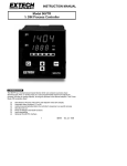
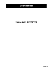
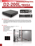
Video Servers
And
Network Cameras
Quick Start Guide
Table of Contents
1. Requirements .................................................................................................3
2. Physical Installation ...........................................................................................4
2.1 Speed Dome Network Camera.................................................................4
2.2 Pan and Tilt Network Camera..................................................................8
2.3 Infra Red Network Camera....................................................................10
2.4 1CH Video Server .................................................................................. 11
2.5 4CH Video Server ..................................................................................15
3. Camera administration .......................................................................................1
Thank you for purchasing Network Cameras for IP surveillance applications. Before
installation, please be sure to read this quick installation guide and user’s manual carefully to
complete machine installation.
1. Requirements
Video Servers & Network Cameras
Network Environment
LAN
10/100M Ethernet
Monitoring System Recommended
System Hardware
· CPU: Pentium III, 800 MHz or above
· Memory Size : 128 MB (256 MB Recommended )
· VGA card resolution : 1024 x 768 or above
System Requirement for Viewer & Recorder Application
Support OS
Win 98 SE , Win 2000 , Win Me , Win XP
System Hardware
1-4 cameras surveillance application
· CPU: Pentium III, 800 MHz or above
· Memory Size : 128 MB (256 MB Recommended )
· VGA card resolution : 1024 x 768 or above
4 or more cameras surveillance application
· CPU: Pentium 4, 1.7G MHz or above
· Memory Size : 512 MB or above
· VGA card resolution : 1024 x 768 or above
2. Physical Installation
2.1 Speed Dome Network Camera
AC Power and Video Output Cable
The AC power input and video output cable are located on the Network Camera’s
back body. The input power is 24VAC. Note that user need to purchase the power
supply additionally according to local electrical specification. Otherwise, the improper
power adapter may damage the unit and result in danger.
The Network Camera also provides composite video output. User can use RCA video
cable to connect the Network Camera with a TV monitor or VCR.
Audio Input Cable
The Network Camera provides audio input to connect with audio source. User can
monitor not only video but also sound.
LAN Cable
LAN cable is used for 10Base-T Ethernet or 100Base-TX Fast Ethernet cabling. This
Ethernet port built NWay protocol can detect or negotiate the transmission speed of
the network automatically. Please use Category 5 “straight through” cable to connect
the Network Camera to an Ethernet switch or hub.
Alarm I/O Cable
The Network Camera provides a cable with 8 wires external alarm I/O. The alarm I/O
is a physical interface to sense and/or activate alarm signals to a variety of external
sensors or alarms.
Speed Dome Camera Installation:
1. Fix the Network Camera to Ceiling
Take out and prepare the Speed Dome IP Cam from carton
Remove the screws from decorate ring and take off this ring
Remove screws from embedded mount and take off this mount
Follow the anti-clockwise direction to take away Speed Dome main body from
embedded mount
Be aware of this wire for safety hook.
Cut a hole as following in the false ceiling
Push the embedded mount into the hole and drive three screws until the embedded
ring fits the ceiling tightly and solidly
Make sure the safety hook is secured and follow the clockwise direction to attach the
Speed Dome main body into the embedded ring.
Use screwdriver to drive screws within Speed Dome main body and embedded ring
Use magnetic screwdriver to fix the decoration ring with screws. The installation of
Speed Dome body is completed.
2. Connect an Ethernet cable with Network Camera
Connect an Ethernet cable with the LAN cable of the Speed Dome Network Camera
and attach it to the network.
3. Connect the external AC power supply to Network Camera
Connect the external AC power supply to the power cable of the Speed Dome
Network Camera. Note: Use the power adapter, 24VAC, included in the package and
connect the other end to wall outlet for AC power.
4. Done
2.2 Pan and Tilt Network Camera
DC Power and Video Output Cable
The DC power input and video output cable are located on the Network Camera’s
back panel. The input power is 12VDC. Note that supply the power to the Network
Camera with standard power adapter included in package. Otherwise, the improper
power adapter may damage the unit and result in danger.
The Network Camera also provides composite video output. User can use BNC video
cable to connect the Network Camera with a TV monitor or VCR.
LAN Socket
Beside the DC power and video output cable, the LAN socket is an RJ-45 connector
for connections to 10Base-T Ethernet or 100Base-TX Fast Ethernet cabling. This
Ethernet port built NWay protocol can detect or negotiate the transmission speed of
the network automatically. Please use Category 5 “straight through” cable to connect
the Network Camera to a 100Mbps Fast Ethernet network switch or hub.
Alarm I/O Connector
The Network Camera provides a terminal block with 8 pins of connectors located on
the center of the back panel. There are 3 pins for two alarm inputs and 5 pins are for
alarm output. The I/O connectors are physical interface to sense and/or activate alarm
signals to a variety of external sensors or alarms.
CF Card Socket
The CF card socket is located on the right side of the back panel of the Network
Camera. User can plug a CF memory card into this socket to store the alarm or
scheduled images. This is very useful to keep the evidence of alarms or scheduled
images for reference.
Factory Default Reset
This button is hidden in the pinhole above the Alarm I/O connector
Microphone
The Network Camera’s has built-in an internal microphone. This microphone is also
hidden in the pinhole above the Alarm I/O connector.
Status and 10/100M Ethernet LEDs
LED stands for Light-Emitting Diode. The Status and Ethernet LEDs are located on
the right side of the back panel of the Network Camera.
P/T Camera Installation:
1. Fix the Network Camera to Ceiling
Use 4 screws to fix the Network Camera onto the ceiling as below. You can
also put the Network Camera on the table directly.
2. Plug an Ethernet cable into Network Camera
Connect an Ethernet cable to the LAN socket located on the Network Camera’s back
panel and attach it to the network.
3. Connect the external power supply to Network Camera
Connect the external power supply to the DC power connector attached on the
extension cable from the Network Camera. Note: Use the power adapter, 12VDC,
included in the package and connect the other end to wall outlet for AC power.
4. Done
2.3 Infra Red Network Camera
Rear Panel Connections:
1. RS-485: To connect to an indoor/outdoor Pan/Tilt scanner unit.
Definition of the RS-485:
Orange: DBlue: D+
2. LAN port: To connect to PC or Hub.
The LAN socket is an RJ-45 connector for connections to 10Base-T Ethernet or
100Base-TX Fast Ethernet cabling. Please use Category 5 “straight through” cable to
connect the Network Camera to a 100Mbps Fast Ethernet network switch or hub.
3. AC power cord & Local Video out (BNC port)
The AC power input and video output cable are located on the Network Camera’s
back panel. The input power is 85~260VAC.
The Network Camera also provides composite video output. User can use BNC video
cable to connect the Network Camera with a TV monitor or VCR.
IR Camera Installation:
1. Fix IR Network Camera to desired location with wall mount fixture
2. Plug-in Network Cable into Ethernet port
Connect an Ethernet cable to the LAN socket located on the Network Camera’s back
panel and attach it to the network.
3. Connect RS485 two wires to RS485 D+ and D- ( if you need to control P/T
scanner)
4. Plug-in Power cable into power socket
5. Connect Video BNC connector to a local TV (for checking camera viewing
angle)
6. Done
2.4 1CH Video Server
Front Panel
LAN Socket
Beside the DC power and video output cable, the LAN socket is an RJ-45 connector
for connections to 10Base-T Ethernet or 100Base-TX Fast Ethernet cabling. Please
use Category 5 “straight through” cable to connect the Video Server to a 100Mbps
Fast Ethernet network switch or hub.
Alarm I/O Connector
The Video Server provides a terminal block with 8 pins of connectors located on the
center of the back panel. There are 3 pins for two alarm inputs and 5 pins are for
alarm output. The I/O connectors are physical interface to sense and/or activate alarm
signals to a variety of external sensors or alarms.
CF Card Socket
The CF card socket is located on the right side of the back panel of the Video Server.
User can plug a CF memory card into this socket to store the alarm or scheduled
images. This is very useful to keep the evidence of alarms or scheduled images for
reference.
Factory Default Reset
This button is hidden in the pinhole above the Alarm I/O connector. Please refer to the
Appendix A in this manual for more information.
Status and 10/100M Ethernet LEDs
LED stands for Light-Emitting Diode. The Status and Ethernet LEDs are located on
the right side of the back panel of the Video Server.
Back Panel
DC-in Jack
The DC power input is located on the back panel of Video Server. The input power is
12VDC. Note that supply the power to the Video Server with standard power adapter
included in package.
Video-in Jacks
The video-in jacks are also located on the back panel of Video Server.
Audio-in Jack
Audio-in jack allows any device that could input audio. For example, microphone, CD
player, etc.
RS485
This is for the P/T/Z camera. After D+ and D- are correctly connected to P/T or P/T/Z
camera, users could control the camera by clicking the direction arrow on the web
homepage.
1CH Video Server Installation:
1. Attach video sources to Video Server
To use Video Server, user must supply video sources to this device. Typical,
user may utilize standard camera, doom camera, bullet camera, P/T camera,
Speed doom camera, or others as the video sources. Connect the BNC
terminal of camera to the Video Server’s video inputs and make sure to power
on these cameras first.
2. Attach Audio source to Video Server (option)
If user needs not only video stream but also audio stream, then the audio
source is attached to Video Server if necessary. User may utilize line output of
standard camera or audio amplifier, or others as the audio source. Connect the
RCA terminal of audio device’s line output to the Video Server’s RCA input and
make sure to power on your camera or audio device first.
3. Plug an Ethernet cable into Video Server
Connect an Ethernet cable to the LAN socket located on the Video Server’s back
panel and attach it to the network.
4. Connect RS485
When users would like to apply a camera with P/T/Z function, they usually need to
connect their communication port (for camera control) through RS485. After RS-485
was correctly connected to D+ and D-, the remote users could control the camera
through Internet.
5. Connect the external power supply to Video Server
Connect the external power supply to the DC power connector attached on the
extension cable from the Video Server. Note: Use the power adapter, 12VDC,
included in the package and connect the other end to wall outlet for AC power.
6. Done
2.5 4CH Video Server
Front Panel
LAN Socket
Beside the DC power and video output cable, the LAN socket is an RJ-45 connector
for connections to 10Base-T Ethernet or 100Base-TX Fast Ethernet cabling. Please
use Category 5 “straight through” cable to connect the 4CH Video Server to a
100Mbps Fast Ethernet network switch or hub.
Alarm I/O Connector
The 4CH Video Server provides a terminal block with 8 pins of connectors located on
the center of the back panel. There are 3 pins for two alarm inputs and 5 pins are for
alarm output. The I/O connectors are physical interface to sense and/or activate alarm
signals to a variety of external sensors or alarms.
CF Card Socket
The CF card socket is located on the right side of the back panel of the 4CH Video
Server. User can plug a CF memory card into this socket to store the alarm or
scheduled images. This is very useful to keep the evidence of alarms or scheduled
images for reference.
Factory Default Reset
This button is hidden in the pinhole above the Alarm I/O connector.
Status and 10/100M Ethernet LEDs
LED stands for Light-Emitting Diode. The Status and Ethernet LEDs are located on
the right side of the back panel of the 4CH Video Server.
Back Panel
DC-in Jack
The DC power input is located on the back panel of 4CH Video Server. The input
power is 12VDC. Note that supply the power to the 4CH Video Server with standard
power adapter included in package.
Video-in Jacks
The 4 video-in jacks are also located on the back panel of 4CH Video Server. You can
Install 4 video cameras and connect it to 4 video-in jacks respectively.
RS485
This is for the P/T/Z camera. After D+ and D- are correctly connected to P/T or P/T/Z
camera, users could control the camera by clicking the direction arrow on the web
homepage.
4CH Video Server Installation:
1. Attach video sources to 4CH Video Server
To use 4CH Video Server, user must supply video sources to this device.
Typical, user may utilize standard camera, doom camera, bullet camera, P/T
camera, Speed doom camera, or others as the video sources. Connect the
BNC terminal of camera to the 4CH Video Server’s video inputs and make
sure to power on these cameras first.
2. Plug an Ethernet cable into 4CH Video Server
Connect an Ethernet cable to the LAN socket located on the 4CH Video Server’s back
panel and attach it to the network.
3. Connect RS485
When users would like to apply a camera with P/T/Z function, they usually need to
connect their communication port (for camera control) through RS485. After RS-485
was correctly connected to D+ and D-, the remote users could control the camera
through Internet.
4. Connect the external power supply to 4CH Video Server
Connect the external power supply to the DC power connector attached on the
extension cable from the 4CH Video Server. Note: Use the power adapter, 12VDC,
included in the package and connect the other end to wall outlet for AC power.
5. Done
3. Camera administration
The Network Camera provides GUI ( Web based, Graphical User Interface ) for machine
management and maintenance.
When you installed your IP camera over your network environment, to start Network Camera
web configuration, you must have the web browsers installed on computer for web
management.
-
Microsoft internet Explorer 5.5 or higher with Java support
Default LAN interface IP address of Network Camera is 192.168.0.20. You may now open your
web browser, and key in http://192.168.0.20 in the address bar of you web browser to logon
Network Camera’s web configuration page.
The Network Camera will prompt for User Name and Password. For the first time, please enter :
admin as username to continue machine Web Management.
1
If difficulty is met, please refer to the following steps to establish the connection:
- Your PC can establish a physical connection to the Network Camera. The PC and the
Network Camera must be directly connected (using the LAN port on the Network Camera.)
or on the same LAN segment. That is the PC must be configured to an IP address and
subnet mask in 192.168.0 x segment. For example: IP: 192.168.0.2, subnet mask :
255.255.255.0.
-
The Network Camera must be installed and powered NO.
-
If the PT Internet Camera’s default IP Address (192.168.0.20) is already used by another
device, the other device must be turned OFF until the Network Camera is allocated a new
IP Address during configuration.
Or you may execute IP Finder to discover PT Camera’s IP address. Before starting installation,
Please ensure that:
Procedures of IP finder utility
-
Please find the IP Finder in the Utility folder on user s manual CD
Double-click the IP Finder and the following screen should be prompt on your computer.
Choose the destination camera for IP address and device name modifications.
- After modifications, you may now connect the camera via web browser.
2