1
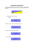
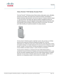
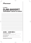
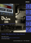
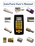
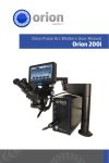
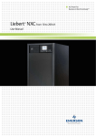
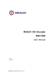
DivisionMaster
operating instructions
For DivisionMaster V2.03, last modified 1 October 2008
INTRODUCTION
Machining operations that involve rotating a part by
a known number of degrees, or by a known fraction
of a circle, are very common in metalworking. Such
operations are numerous and varied, but obvious
examples might include cutting gear wheels, engraving graduations on handwheels, and cutting the transfer ports on a two-stroke piston.
Manual techniques for achieving accurate rotation
involve the use of a dividing head, or a rotary table,
or performing division in the lathe with the help of a
division plate attached to the headstock, or a dividing
attachment (such as the one described by G.H. Thomas for the Myford lathes1) that uses a worm to drive
the lathe’s “Bull Wheel”. These techniques are welldescribed in the literature, along with the pitfalls one slip when counting the holes in the division plate,
or the number of rotations of the indexing arm, and
the result is that your gear wheel has a thin (or thick)
tooth, and an evening’s work has just headed for the
scrap box. Even when all goes well, the necessity of
checking and re-checking between each move means
that manual indexing and dividing techniques are at
best very slow, cumbersome, and tedious.
For those engineers that have the luxury of a CNC
mill that has a 4th (rotary) axis, life is very much simpler. The 4th axis, under control of the CNC system,
can be made to automatically rotate the part between
cuts, and with the right motion control program, can
be made to rotate the part during a cut, allowing complex profiles such as cams and turbine blades to be
machined.
DivisionMaster provides a half-way house between
the fully manual and the fully automated worlds.
With the addition of a stepper motor to your favourite
headstock dividing attachment, dividing head, or
1.Described in his book “Dividing and Graduating”.
rotary table, DivisionMaster can operate as an
“Automatic Indexer”; you set it for the number of
degrees per move, or the number of divisions, that
you wish to use, and a single keystroke will then
cause DivisionMaster to move the part to the next
angular position or division.
For those that already have a 3-axis CNC mill, DivisionMaster can be pressed into service as a 4th axis
motor controller, accepting either step-and-direction
commands from the parent CNC control, or simple
contact closure signals to simulate the operation of
the forward/back keys on the keyboard. Unlike a conventional 4th axis option on a CNC mill, using DivisionMaster as the 4th axis control means that you can
use its automatic indexing ability with other devices
as well if need be, rather than having it dedicated to
use with the CNC mill.
DivisionMaster’s power stage is a bipolar “chopper”
design, intended to drive bipolar stepper motors of up
to 2 amps per phase at its supply voltage of 19V. This
places a practical limit on the size of stepper motor
that it can drive directly—NEMA 23 size motors generally being the largest that will fit this specification.
However, the step-and-direction drive signals that
DivisionMaster generates can be used to drive a more
powerful external power stage if it is necessary to use
larger stepper motors than the internal power stage
can handle.
The stepper motors supplied by DivisionMaster
range from a single stack NEMA 23 6-wire motor
rated at around 97 oz-inches of holding torque, that is
capable of driving a small rotary table such as the
excellent 4” tables supplied by Taig or Sherline2,
through to a triple stack NEMA 23 8-wire motor rated
at 227 oz-inches of holding torque, that is capable of
2.The motor torque required to drive a given rotary device will depend on the
worm ratios involved, and the viscous and/or frictional drag “seen” by the motor
when driving the reduction gearing. The Taig and Sherline tables are very free
running, employing ball races either end of the worm and at the base of the table
spindle, and therefore require relatively little motor torque to drive them.
Page 1
DivisionMaster Operating Instructions
Copyright © 2008 DivisionMaster Ltd.
driving the rotary tables and BSO dividing heads
manufactured by Vertex. DivisionMaster can also
supply motor mounts and couplings suitable for use
with the Vertex HV4 and HV6 rotary tables, and the
BSO dividing head.
OVERVIEW OF OPERATION
A NOTE
Figure 1 shows the layout of the DivisionMaster front
panel.
ON
SAFETY
CONTROLS
Using machinery of any kind inevitably brings with it
a variety of safety issues. For example, DivisionMaster is able to control stepper motors, which in turn
may be driving reduction gearing that can multiply
the spindle torque of the motor by a couple of orders
of magnitude; the consequences if body parts get
trapped by a moving rotary axis can therefore be very
unpleasant. Similarly, as DivisionMaster, and its
associated rotary axis, are intended for use with lathes
or mills, further hazards exist relative to the operation
of the associated machinery.
D iv is io n M a s t e r
^
As with any other workshop machinery, the use of
appropriate safety measures is essential at all times
that the unit is powered on. In particular, DO NOT
touch or adjust the rotary components controlled by
the DivisionMaster unit while it is connected to a
power supply.
PRV
<-1/100
1
2
4
5
7
8
STOP
0
-1
The unit has a membrane keyboard, intended to prevent ingress of dust and swarf through the top panel;
however, it should be noted that the case is NOT
proof against ingress of oils, cutting fluids, or water,
and contact with these materials may result in catastrophic failure of the unit.
The ventilation fan is provided to ensure that the
operating components of the unit are kept cool;
obstruction or failure of the fan will result in overheating and potential damage to the circuitry.
The case is not designed to cope with physical abuse;
it should be treated as you would expect to treat a
hand-held calculator or pocket computer.
+>
+1/100
^
CONSIDERATIONS
The unit is ventilated via a small fan on the underside
of the case; the intake to the fan will prevent the
ingress of the majority of shop swarf, but is not
intended to be a particle filter. Hence, it is unwise to
use this unit in an environment where it will be subjected to significant amounts of airborne dust unless
additional filtering is provided.
Exit
NXT
-1/10
PHYSICAL
Exit
-10
3
+1/10
6
+1
9
+10
OK
Figure 1. DivisionMaster control panel
At the top is a two-line by 16-character LCD display;
immediately below the display are four keys arranged
in a diamond pattern. These four keys are the “cursor” keys—allowing movement between operating
modes, and movement of the cursor when entering
values, as well as giving commands to step the motor
forwards or backwards.
Below the cursor keys is a numeric keypad, allowing
the numbers from 0 through 9 to be entered, plus two
special keys marked “STOP” and “OK”. The “OK”
key serves a similar function to the “Enter” key on a
computer keyboard; the “STOP” key will abort any
Page 2
DivisionMaster Operating Instructions
Copyright © 2008 DivisionMaster Ltd.
motion of the motor within one motor step period3, in
any of the operating modes other than “Driver” mode.
The use of the keypad will be described more fully
along with the detailed operation of the different
modes.
A single red LED is visible through the panel membrane above the right hand side of the keyboard. This
LED is illuminated when the unit initiates a move
(i.e., the motor is moving), and is turned off at the end
of a move.
The rear panel of DivisionMaster’s box carries three
sockets, as can be seen in Figure 2 and Figure 3. Figure 2 shows the original plastic cased version of the
controller; Figure 3 shows the metal cased version.
also achieved via the earth pin of the IEC connector
on the power supply. FOR THE SAFETY OF THE
DIVISIONMASTER UNIT AND ITS OPERATOR, always ensure that a proper earth connection to the unit is present.
The middle socket is the external I/O socket—a 9-pin
D-type socket, used to carry various input and output
signals to and from the unit.
At the right is either a 6-pin DIN socket (plastic cased
version) or a 4-pin XLR socket (metal cased version).
This is used to connect the unit to a stepper motor.
ALWAYS POWER OFF THE UNIT before the
motor is plugged into or unplugged from this
socket. Failure to do so may permanently damage
the drive circuitry.
OPERATING MODES
There are five “normal” operating modes:
• Setup mode;
• Jog mode;
Figure 2. DivisionMaster socket panel
• Division mode;
• Degrees mode; and
• Continuous mode.
Figure 3. DivisionMaster socket panel
The power socket at the left is a conventional 2.1mm
power jack socket, accepting the type of plug commonly seen on the external power supplies known
colloquially as “wall warts”. The power supply
offered with DivisionMaster is a switch-mode “universal” supply capable of generating 2.4 amps at 19
volts from a mains voltage of 110-240Vac. There is
no separate on/off switch; powering on the supply
will also power on DivisionMaster if the supply is
plugged into the unit.
Below the power socket on the metal cased version of
the controller is a self-tapping screw that provides an
earthing point for the unit. Earthing of both units is
3.Given that the motor speed ranges from 3 steps per second to 9999 steps per
second, at the slowest speed setting it can take up to 1/3 of a second for the
machine to register that the stop key has been pressed.
Setup mode is used to set DivisionMaster’s operating
parameters, such as the worm ratio used in the dividing attachment, and the motor current and feed rates
to be used. All of DivisionMaster’s operating parameters are under software control, so there are no jumpers to set or resistor values to choose in order to make
it work in the desired configuration. The operating
parameters are stored in non-volatile RAM within
DivisionMaster’s memory space, so that the next
time the unit is powered on, its operating parameters
will be as they were last configured. Four independent sets of operating parameters can be stored; this
allows the correct parameters to be stored and
recalled for up to four different rotary devices.
Jog mode allows the dividing attachment to be
“jogged” into a suitable starting position, using increments of between 1/100th of a degree and 10 degrees
per jog, in either direction.
Division mode allows the dividing attachment to be
stepped forwards and backwards, with each incremental movement being an integral fraction of 360
Page 3
DivisionMaster Operating Instructions
Copyright © 2008 DivisionMaster Ltd.
degrees. Any number of divisions between 1 and
9999 can be programmed into the device.
over a full rotation, and so do not accumulate to give
an undesirable “thick” or “thin” division.
Degrees mode allows the dividing attachment to be
stepped forwards and backwards, with each incremental movement being an angle in degrees and fractional degrees to 3 decimal places, i.e., in the range
0.001 degrees to 360.000 degrees.
An “ideal” drive ratio for use with DivisionMaster
might be considered to be 90:1, which yields 1/100th
of a degree per half-step, and therefore matches the
“Jog” resolution exactly; however, DivisionMaster
can be configured to work with any chosen drive ratio
between 1:1 and 5000:1 as a user-configurable
option. This means that DivisionMaster could be
used with drive ratios that are difficult to use with
conventional division plate approaches—for example, with the G.H. Thomas dividing attachment fitted
to a Myford ML7 lathe, where the “Bull Wheel” that
is used as the worm wheel has 65 teeth. With DivisionMaster driving the worm via a stepper motor, this
will give approximately 0.0138 degrees of spindle
movement per half-step, and, as DivisionMaster
always calculates to the nearest half-step, the theoretical resolution with this setup will be within 0.0069 of
a degree.
Continuous mode allows the dividing attachment to
be rotated continuously until the operator explicitly
requires the device to stop.
Stepping between the operating modes is achieved by
using the “cursor keys” that are marked PRV and
NXT. Pressing NXT steps through the modes in the
order Setup -> Jog -> Division -> Degrees -> Continuous -> Setup; pressing PRV steps through the operating modes in the reverse direction.
Once the desired mode has been selected on the display, the mode is entered by pressing the OK key; see
the individual mode descriptions for the command
sequences that apply in each case.
A further mode, Driver mode, is selected by holding
down the STOP key (or shorting the corresponding
STOP pin on the 9-pin D-type connector to the
ground pin) during the unit’s power-up sequence. In
this mode, the keyboard is inactive, and the unit will
accept step-and-direction commands via the appropriate pins on the D-type connector. Driver mode
allows the unit to be used as a dedicated 4th axis
driven by an external CNC control.
RESOLUTION
The actual resolution attainable in the three active
modes (Jog, Division, and Degrees) will depend upon
the drive ratio between the stepper motor and the
dividing attachment’s output shaft. The stepper motor
is driven in “half step” mode, giving 400 (half) steps
per motor rev for a normal 1.8 degrees-per-step
motor; with the Taig or Sherline rotary table, which
have a 72:1 worm ratio, this means that a single halfstep represents 1/80th of a degree of table movement.
DivisionMaster will always convert the “desired”
position of the dividing attachment (which, in
Degrees mode, may be specified to a precision of
thousandths of a degree) into an integral number of
half-steps, ensuring that each move is no more than a
quarter of a motor step away from the desired position, and ensuring that the errors are evenly spread
The actual resolution attainable is ultimately limited
by the accuracy of the mechanical components used.
If the dividing attachment itself is inherently inaccurate, DivisionMaster cannot correct its inaccuracies.
BACKLASH
COMPENSATION
Geared or worm-driven dividing devices will have
some degree of backlash in the drive train, unless
they have been designed with the use of anti-backlash
gearing. While there is often provision for reducing
the backlash by adjusting the gear train or the position
of the worm, it is often difficult to remove backlash
altogether without increasing the friction in the drive
to the point where it becomes difficult to drive with a
stepper motor. Hence, backlash is often a compromise between usability on the one hand and accuracy
on the other.
DivisionMaster can provide some degree of backlash
compensation in order to reduce the effects of any
backlash that is present in the system. One of the
setup parameters allows the user to define backlash
compensation as a number of motor half-steps, chosen to be slightly more steps than necessary to take up
the drive’s backlash. Whenever DivisionMaster is
asked to perform a move in the counter-clockwise
direction, this number of half-steps is added onto the
move so that the rotary axis overshoots. The rotary
axis is then driven clockwise by this same number of
steps, so that it approaches its final position in the
Page 4
DivisionMaster Operating Instructions
Copyright © 2008 DivisionMaster Ltd.
clockwise direction, regardless of whether the move
was clockwise or anticlockwise. This is similar to the
approach taken with a manual dividing attachment if
there is a need to reverse the direction of motion.
which the motor can reliably start, and ramp up from
that to the desired Max value.
MOTOR
The D-type socket on the back panel of the unit carries a number of I/O signals that allow DivisionMaster to be interfaced to external devices in various
ways:
CURRENT
The internal motor drive circuitry of DivisionMaster
can drive stepper motors at up to 2A/phase. Setup
mode allows the current setting to be adjusted to suit
the motor that will be used to drive the rotary axis.
While the motor is being stepped, this current setting
will be used; once the stepping sequence has finished,
the motor current is reduced to a percentage of the full
motor current4, again configurable in the setup mode.
This allows the motor to hold position at the end of a
move so as not to lose accuracy, while reducing the
heat dissipation in the driver and motor coils while
the motor is sitting idle. In Driver mode, DivisionMaster monitors the step and direction inputs for
activity, and automatically sets the motor current to
the reduced value after 2 seconds of inactivity.
MOTOR
SPEEDS
The drive logic of the DivisionMaster controller
allows the motor speed to be controlled during a
move. Two speed ranges can be set by the operator; a
fast speed range and a slow speed range. For each
speed range, a minimum and maximum speed can be
specified, along with a ramp rate. The speeds are
specified in motor steps per second, in the range 3
steps per second to 9999 steps per second. The minimum speed is the speed used at the start of a move,
and the ramp rate controls how rapidly the motor is
accelerated to the maximum speed, and then decelerated at the end of the move. The ramp rate is in no
particular units; a larger number gives faster acceleration. If the minimum and maximum speeds for a
given speed range are set to the same value, then there
will be no ramping, and the motor will be driven at
that speed. However, at the high end of the speed
range, as stepper motors deliver less torque at high
speeds, it may be impossible for the motor to start at
a high initial speed; in such cases, it is necessary to
reduce the Min speed for the speed range to a value at
4.This applies to Degrees, Division, and Driver modes only. In Jog mode, the
motor current is reduced to zero after a move has been completed, allowing manual positioning of the rotary axis if such provision is available.
EXTERNAL I/O
• The “<-”, “+>”, and “STOP” keys are replicated on
three pins of the socket, allowing external switch
contacts to control the indexer position, and to perform emergency stop functions;
• One of the pins can be used to signal whether a
move is in progress—this can be used in conjunction with the “<-” and “+>” keys to coordinate
actions with an external CNC controller;
• Three pins are used for Step, Direction, and Enable
signals—either as outputs from DivisionMaster to
an external power stage (in Jog, Division, and
Degrees modes), or as inputs to DivisionMaster
from a CNC control (in Driver mode);
• The two remaining pins provide 0V (Ground) and
+5V; these are primarily used as “common” reference signals for connecting to external devices, but
the +5V can provide a limited amount of power if
necessary, up to a maximum of 500 mA.
OPERATING
DIVISIONMASTER
DivisionMaster is very simple to operate, and familiarity with the controls should be achievable very
quickly. Later sections of these operating instructions
describe how to wire up motors and external interface
connections; for the moment, the description assumes
that a rotary device (dividing head, rotary table...etc)
is available, fitted with a suitable stepper motor that
has been wired up to a 4-pin XLR plug, and the unit
is being used without making external I/O connections of any kind via the D-type connector.
Before inserting the power plug:
• Ensure that a suitable earth connection is made to
the unit (see “Physical Considerations” above)
• Insert the 6-pin DIN plug or 4-pin XLR plug in the
socket on the back of the unit. Care should be taken
Page 5
DivisionMaster Operating Instructions
Copyright © 2008 DivisionMaster Ltd.
to get the orientation of the plug right; the XLR
plug has an indentation in its outer metal shell that
locates in a corresponding indentation at the top
left of the XLR socket, and the DIN plug has an
indentation that locates at the bottom of the DIN
socket.
There is no on/off switch in the unit; power is
switched on and off via the mains adaptor supplied
with the unit. Plug in the mains adaptor and switch it
on; DivisionMaster’s display should show “DivisionMaster” on the first line, and the software version
number and release date on the second line, for a few
seconds, before displaying:
From the Setup mode selection screen, pressing OK
will cause Setup mode to be entered. The screen will
then show the first setup option, which is to confirm
or change the Parameter Set that is to be used:
Parameter set = 0
The cursor will be flashing over the number 0; typing
in any number in the range 0 through 3 allows the
operator to determine which parameter set to load
from memory if the desired set differs from the
parameter set number shown.
Pressing the “NXT” or “OK” keys confirms the
parameter set number selected.
Parameter set= 0
<
Prv/Nxt
>
The next screen shows the start of the options for
modifying the parameter set that has been selected:
This allows the user to select one of four sets of operating parameters, the sets being numbered 0, 1, 2, and
3 (see Setup Mode below for details of what these sets
of parameters can do). The number can be changed by
pressing the numeric keys on the keyboard; once the
chosen number has been selected, pressing “OK” or
the PRV or NXT keys will take you to the mode selection screens, starting with Jog Mode. Pressing the
PRV or NXT keys cycles through the different operating modes; pressing the OK key selects the operating mode that is currently shown on the screen. So,
pressing PRV from the jog Mode selection screen
takes you to the Setup Mode selection screen.
Factory Settings?
SETUP
MODE
This mode allows the operator to set and save the
operating parameters of the unit. The Setup mode
selection screen looks like this:
As with the mode selection screens, the PRV and
NXT keys can be used to scroll through the list of
parameter settings.
Pressing OK to Factory settings? will set all
of the parameters in this parameter set to their factory
default values, and the display then steps to the next
setup option:
Restore settings?
Pressing OK to Restore settings? causes the
last stored set of values for this parameter set to be
retrieved and used as the current settings. This can be
useful in cases where the operator decides that the
changes made were inappropriate, and considers it
desirable to return to a known state.
The next setup option is:
Max amps = 1.5
As with most of the screen displays, the second line
gives some hints as to what the operator can do next.
Pressing the PRV key displays the PReVious mode
selection screen (in this case, Degrees mode); pressing the NXT key displays the NeXT mode selection
screen (in this case, Jog mode).
The Max amps value, which has a factory setting of
1.5, defines the current in amps that the unit will use
as the maximum value of motor current in each winding (phase) of the motor, when the motor is being
stepped. The appropriate value for this parameter is
usually printed on the body of the motor itself; in the
case of motors supplied by DivisionMaster, the setting can be found in the separate data sheet provided
with the motor.
The first line identifies that “paramSet 0” is currently
in use. There are four independent sets of operating
parameters (paramSets) stored in the machine, numbered 0 through 3. The parameter sets are stored in
non-volatile memory, so they are maintained from
one use of the controller to the next.
This parameter can be set to any value in the range 0.0
through 2.0. Initially, the first digit of the value is
highlighted by a flashing cursor; pressing any of the
numbers 0 through 9 on the keypad causes the current
digit position to be overwritten with that number, and
the cursor moves to the next digit to the right. The <
SETUP paramSet 0
Prv/Nxt
OK
Page 6
DivisionMaster Operating Instructions
Copyright © 2008 DivisionMaster Ltd.
and > cursor keys can also be used to move the cursor
left or right respectively. The display “wraps”—that
is to say, moving right from the right-most cursor
position takes you to the left-most, and vice-versa.
With a 2-digit parameter, this means that there is no
difference between cursor right and cursor left, but
with 3 or more digits on the display, as will be seen
later, this becomes more relevant.
The next setup option is:
Idle amps = 050%
The Idle amps setting, which has a default factory
setting of 50%, defines the percentage of Max amps
that is used by the unit when the motor is idle, i.e.,
when it has completed a move in Division or Degrees
modes, or when no external control signal change has
happened for 2 seconds in Driver mode. The intention
of this setting is to ensure that the motor holds position, but does not consume excessive power (and
therefore generate excessive heat) when it is doing no
work. Idle amps can be set to any value in the
range 000% through 100%.
In most applications of DivisionMaster, where the
motor is driving via a worm drive, there is no reason
to change the factory setting of 50%, as the worm
drive itself will prevent forces on the rotary axis from
being transmitted back to the motor. However, if
direct gearing and low gear ratios are used, it may be
desirable to increase the idle current setting to prevent cutting forces from overcoming the motor’s
holding torque, thereby causing loss of position.
The next setup option is:
Worm ratio= 0090
The Worm ratio setting, which has a factory setting of 90:1, allows the operator to define what drive
ratio exists between the motor shaft and the output
shaft of the rotary axis. Any value between 1 and
5000 can be used for this parameter; if 0000 is
entered, then the value set will actually be 0001.
The next setup option is:
+ve move = CW
The +ve move setting, which has a factory setting
of CW, allows the operator to define what rotational
direction of the rotary axis will result when the operator makes a +ve move. Toggling between CW
(clockwise) and CCW (counter clockwise) is
achieved by means of the cursor control keys, < and
>.
The next setup option is:
Divisions= 0060
The Divisions setting, which has a factory setting of 0060, allows the operator to define the default
number of divisions to be used in Division mode. The
range of permitted values is 1 though 9999. If a particular number of divisions is used frequently, then
this parameter should be set to that number; it doesn’t
prevent other numbers of divisions being used, but
makes life slightly easier when that is the number you
want.
The next setup option is:
Degrees= 030.000
The Degrees setting, which has a factory setting of
030.000, allows the operator to define the default
number of degrees to be used for moves in Degrees
mode. The range of permitted values is 0.001 though
360.000. If a particular angle is used frequently, then
this parameter should be set to that angle; it doesn’t
prevent other angles being used, but makes life
slightly easier when that is the angle you want.
The next setup option is:
Slow Min= 0200
The Slow Min setting, which has a factory setting
of 0200, allows the operator to define the initial
motor speed, in motor steps per second5, to be used
for moves using the slow speed range. A larger value
gives a faster rate of rotation. The range of permitted
values is 3 through 9999.
The next setup option is:
Slow Max= 0400
The Slow Max setting, which has a factory setting
of 0400, allows the operator to define the maximum
motor speed, in motor steps per second, to be used for
moves that use the slow speed range. Larger values of
this parameter represent faster motor speeds. The
range of permitted values is 3 through 9999; however,
its value is constrained to be no smaller than the value
of Slow Min.
The next setup option is:
Slow Ramp= 08
5.The motor speeds defined are not precise; i.e., although the resultant motor
speed will be a close approximation to the requested value, it is not close enough
to turn your rotary table into a Quartz clock, or to achieve precise synchronization with other, independently controlled, rotating devices.
Page 7
DivisionMaster Operating Instructions
Copyright © 2008 DivisionMaster Ltd.
The Slow Ramp setting, which has a factory setting
of 08, allows the operator to define the rate at which
the motor speed will be ramped from the Slow Min
speed to the Slow Max speed. Larger values represent
faster ramping rates. The range is 1 through 99.
check the settings again before committing them to
memory, the PRV and NXT keys can be used to step
through the parameters - PRV takes you back to the
Backlash setting, NXT takes you forward to the
Factory Settings? option.
The next setup option is:
Pressing OK to Save and exit? will take you to
Jog mode.
Fast Min= 0350
The Fast Min setting, which has a factory setting
of 0350, allows the operator to define the initial
motor speed, in steps per second, to be used for
moves that use the fast speed range. Larger values of
this parameter represent faster motor speeds. The
range of permitted values is 3 through 9999.
The next setup option is:
Fast Max= 0700
The Fast Max setting, which has a factory setting
of 0700, allows the operator to define the maximum
motor speed, in steps per second, to be used for
moves that use the fast speed range. Larger values of
this parameter represent faster motor speeds. The
range of permitted values is 3 through 9999; however,
its value is constrained to be no smaller than the value
of Fast Min.
JOG
MODE
The purpose of Jog mode is to provide a means to set
the orientation of the rotary axis to the correct starting
point for a sequence of moves—i.e., to define where
“zero” (zero degrees in the case of a subsequent
Degrees mode move, or the zero’th division in the
case of a subsequent Division mode move) is. When
entering either Division mode or Degrees mode,
DivisionMaster assumes that the rotary axis has been
set to its zero point, and performs all subsequent calculations accordingly.
The next setup option is:
Fast Ramp= 08
The Fast Ramp setting, which has a factory setting
of 08, allows the operator to define the rate at which
the motor speed will be ramped from the Fast Min
speed to the Fast Max speed. Larger values represent
faster ramping rates. The range is 1 through 99.
The next setup option is:
Backlash= 000
The Backlash setting, which has a factory setting
of 000, allows the operator to define the number of
motor half-steps that will be used in the backlash control algorithm. This parameter should be set to a value
that is at least as great as the actual backlash present
in the drive train between the motor shaft and the
rotary axis.
Figure 4. Jog mode selection screen
The final stage in Setup mode is:
Save and exit?
On entering Jog mode, by pressing OK, the screen
display shows the following:
This is the only way to get out of Setup mode, and
when accepted (by pressing OK), causes all of the
changes that you have made to the current parameter
set to be saved to non-volatile memory. If you wish to
Jog mode 000.000
-
Exit
+
Page 8
DivisionMaster Operating Instructions
Copyright © 2008 DivisionMaster Ltd.
The number on the first line, 000.000, shows the current target position for the rotary axis, in degrees, relative to zero (the position on entry to Jog mode). This
target position can be incremented or decremented, in
units of 1/100th, 1/10th, 1, or 10 degrees, depending
upon which keys are pressed by the operator. The
keypad legend identifies the relevant keys (see Figure
1). The <- and +> keys increment or decrement by 1/
100th of a degree; the 1 and 3 keys by 1/10th of a
degree; the 4 and 6 keys by 1degree; and the 7 and 9
keys by 10 degrees.
DivisionMaster will then drive the motor by the
number of steps required to move the rotary axis to
that target position; if the drive ratio is something
other than 90:1 (which would give 1/100th of a
degree per motor half-step), then there may be a discrepancy between the target position and the actual
position, as DivisionMaster cannot do better than
position the rotary axis to the nearest half-step in this
case. The display then shows the actual position on
the second line. For example, when using a 72:1
worm ratio6, if the +> key is pressed once to rotate the
rotary axis 1/100th of a degree clockwise, the display
becomes:
and the target position; any error in the actual position
can be corrected by reversing the move that was
stopped, and then repeating the move.
The PRV and NXT keys (also marked “Exit” on the
legend) are used to exit from Jog mode. PRV will
cause the display to return to the pervious mode
selection screen (Setup mode); NXT steps on to the
next mode selection screen (Division mode).
DIVISION MODE
As pointed out in the description of Jog Mode, the
position of the rotary axis on entry to this mode is
assumed to be the zero point, and all subsequent calculations are based on that assumption. Hence, accurately positioning the axis before entry to Division
mode is of vital importance if subsequent machining
operations are to be correctly placed around the
workpiece.
On entering Division mode, by pressing OK, the
screen display shows the following:
Divisions= 0060
<
Jog mode 000.010
-
000.013deg
+
A single half-step has been issued to the motor, and
the positional error is 0.003 degrees.
DivisionMaster always displays angular positions
modulo 360 degrees—i.e., if the “true” value is
greater than 360.000 degrees, then the value displayed is the remainder that results from dividing the
“true” value by 360.
This “wrapping” behaviour works with either CW or
CCW moves. Incrementing 359.000 degrees by 10
degrees results in 009.000 being displayed; conversely, decrementing 000.100 by 1 degree results in
359.100 being displayed
The Slow Min and Fast Min speeds are used for
all Jog moves; the motor speed is ramped up from the
slow speed to the fast speed, and then ramped back
down to the slow speed at the end of the move, using
the Slow Ramp ramp rate.
Pressing the STOP key during any move causes the
move to stop on completion of the current motor
step7. The display shows the actual angular position
6.With a drive ratio of 72:1, the rotary axis is moved 1/80th of a degree per motor
half-step.
Prv/Nxt
>
The number on the top line is the default number of
divisions, as defined in Setup mode (or the factory
default value if this hasn’t been changed). This value
can either be changed to the desired number of divisions, in the range 1 through 9999, by using the < and
> cursor keys and the number keys, or accepted by
pressing NXT or OK. The display now changes to
show:
Div 0000 of 0060
-
Exit
+
The left hand number shows the current division
number (0000), and the right hand number shows the
number of divisions that has been chosen (0060).
Pressing the +> key will cause the rotary axis to be
moved to the next division in a CW direction, drive
the rotary axis in a CW direction, starting at the Fast
Min speed, and ramping up to the Fast Max speed,
using the value defined for Fast Ramp; the speed is
ramped down again at the end of the move. Pressing
the <- key will make a counterclockwise move, drive
the rotary axis in a CW direction, starting at the Fast
7.Given that the motor speed ranges from 3 steps per second to 9999 steps per
second, at the slowest speed setting it can take up to 1/3 of a second for the
machine to register that the stop key has been pressed.
Page 9
DivisionMaster Operating Instructions
Copyright © 2008 DivisionMaster Ltd.
Min speed, and ramping up to the Fast Max speed,
using the value defined for Fast Ramp; the speed is
ramped down again at the end of the move.
Pressing the 3 key will cause the rotary axis to be
moved to the next division in a CW direction, drive
the rotary axis in a CW direction, starting at the Slow
Min speed, and ramping up to the Slow Max speed,
using the value defined for Slow Ramp; the speed is
ramped down again at the end of the move. Pressing
the <- key will make a counterclockwise move, starting at the Slow Min speed, and ramping up to the
Slow Max speed, using the value defined for Slow
Ramp; the speed is ramped down again at the end of
the move.
can be ignored for most practical purposes. Table 1
shows the theoretical angle and the angle calculated
by DivisionMaster for all 13 divisions (again, using a
drive ratio of 72:1 as the example).
The largest error shown here is -0.0058 degrees,
which is still within a quarter of a motor step of the
theoretical angle (a quarter of a motor step with a 72:1
ratio is 0.00625 degrees).
Note that after executing step 13 in the above
sequence, the current step number shows 0 rather
than 13, as 13 steps has brought the rotary axis full
circle.
Which is what you would expect, as 1/60th of 360
degrees is 6 degrees, which, if a 72:1 drive ratio is
used, is a whole number of motor half-steps. However, if you took a more difficult example, such as 13
divisions, the display after the first step would show:
Pressing the PRV key returns you to the initial screen
of Division mode - where the number of divisions can
be set. It is possible to make a number of moves using
one number of divisions, then change the number of
divisions, and make further moves at the new setting.
DivisionMaster will calculate the step number that is
nearest to (smaller than or equal to) the current angular position of the rotary axis, and this step number is
displayed once the new number of divisions has been
accepted. There may be an error between the actual
position of the axis and the angle for the displayed
step number; this can be corrected by stepping back
one division and then stepping forward one division.
For example, if the rotary axis had been positioned to
step 5 of 13 divisions, the display would show:
Div 0001 of 0013
Div 0005 of 0013
-
-
At the end of the move, the display is updated to show
the new division number, and the bottom line shows
the actual angular position attained as a result of the
move. For example, the first clockwise step of 60
steps would produce the following display:
Div 0001 of 0060
-
006.000deg
027.688deg
TABLE 1. Illustration
+
+
Theoretical
angle
Calculated
angle
Positional
error
1
27.6923
027.688
0.0043
2
55.3846
055.388
-0.0034
3
83.0769
083.075
0.0019
4
110.7692
110.775
-0.0058
5
138.4615
138.463
-0.0015
6
166.1538
166.150
0.0038
7
193.8461
193.850
-0.0039
8
221.5384
221.538
0.0004
9
249.2307
249.225
0.0057
10
276.9230
276.925
-0.002
11
304.6153
304.613
0.0023
12
332.3076
332.313
-0.0054
0 (13)
360.0 (0)
000.000
0
+
If the number of divisions is changed to 20, the display would then show:
of positional error
Current step
number
138.463deg
Div 0007 of 0020
-
Exit
+
on return from changing the number of steps. The
motor has not been stepped, so the actual angular
position is still 138.463 degrees, which is clearly
wrong, as 7/20ths of 360 degrees is more usually 126
degrees. Stepping back and forward one step results
in the following display:
Div 0007 of 0020
-
A single division should be 27.6923 degrees, so the
actual position is in error by 0.0043 degrees, which
126.000deg
+
Pressing the STOP key during any move causes the
move to stop on completion of the current motor
step8. The display shows the actual angular position
and the current step number; any error in the actual
Page 10
DivisionMaster Operating Instructions
Copyright © 2008 DivisionMaster Ltd.
position can be corrected by reversing the move that
was stopped, and then repeating the move.
Pressing the NXT key allows the current division
number to be edited; this allows the operator to “Go
To” a specific division number, rather than stepping
from one division to the next or previous division.
The display shows the following:
Go to 0007
-
Prv/Nxt
+
where the number shown after Go To is the current
division number. This number can be edited using the
< and > keys and the numeric keypad, in order to
define the division number that the operator wishes to
select. The value is constrained in the range 0 to one
less than the current number of divisions. Pressing
OK accepts the number entered, and the display
shows:
Div 0015 of 0020
-
Execute?
+
At this point, pressing any of the <-, ->, 1, or 3 keys
will cause the “Go to” to execute, in the direction and
speed selected; for example, if the 3 key is selected,
the rotary axis is driven in a CW direction until the
selected division is reached, using the Slow speed
range.
DEGREES
MODE
Degrees mode is very similar in operation to Division
mode—the main difference being that the size of
rotary move is expressed as a number of whole and
fractional degrees, rather than as a fraction of a circle.
As pointed out in the descriptions of Jog mode and
Division mode, the position of the rotary axis on
entry to this mode is assumed to be the zero point, and
all subsequent calculations are based on that assumption. Hence, accurately positioning the axis before
entry to Degrees mode is of vital importance if subsequent machining operations are to be correctly placed
around the workpiece.
On entering Degrees mode, by pressing OK, the
screen display shows the following:
Degrees= 030.000
<
The Go To feature can be particularly useful in situations where large numbers of divisions are being
used, but it is not required to perform a machining
operation at every division. In such cases, tedius repetition of a move to reach the desired position is
avoided.
Exit from Division mode requires the PRV key to be
pressed—once to get back to the divisions editing
screen, and once more to return to mode selection—
this will bring you back to the Jog mode selection
screen. Press NXT a couple of times and the Degrees
mode selection screen is displayed.
8.Given that the motor speed ranges from 3 steps per second to 9999 steps per
second, at the slowest speed setting it can take up to 1/3 of a second for the
machine to register that the stop key has been pressed.
>
The number on the top line is the default number of
degrees, as defined in Setup mode (or the factory
default value if this hasn’t been changed). This value
can either be changed to the desired number of
degrees, in the range 000.000 through 360.000, by
using the < and > cursor keys and the number keys, or
accepted by pressing NXT or OK. The display now
changes to show:
000.000
-
The Go to can be cancelled by pressing the PRV or
NXT keys, in which case, the display reverts to its
state before the Go To command was used.
Prv/Nxt
030.000
Exit
+
The left hand number shows the current target angular position (000.000 degrees), and the right hand
number shows the size of move, in degrees, that has
been chosen (030.000). Pressing the +> key will
cause the rotary axis to be moved in a CW direction
by that number of degrees, starting at the Fast Min
speed, and ramping up to the Fast Max speed, using
the value defined for Fast Ramp; the speed is ramped
down again at the end of the move. Pressing the <key will make a counterclockwise move, drive the
rotary axis in a CW direction, starting at the Fast Min
speed, and ramping up to the Fast Max speed, using
the value defined for Fast Ramp; the speed is
ramped down again at the end of the move.
Pressing the 3 key will cause the rotary axis to be
moved in a CW direction by that number of degrees,
starting at the Slow Min speed, and ramping up to the
Slow Max speed, using the value defined for Slow
Ramp; the speed is ramped down again at the end of
Page 11
DivisionMaster Operating Instructions
Copyright © 2008 DivisionMaster Ltd.
the move. Pressing the 1 key will make a counterclockwise move, drive the rotary axis in a CW direction, starting at the Slow Min speed, and ramping up
to the Slow Max speed, using the value defined for
Slow Ramp; the speed is ramped down again at the
end of the move.
At the end of the move, the display is updated to show
the new target position, and the bottom line shows the
actual angular position attained as a result of the
move. For example, two clockwise moves of 32.198
degrees would produce the following display:
064.396
-
032.198
064.400deg
+
As with the earlier division examples, the actual position differs from the target position by no more than
1/4 of a motor step.
As with Division mode, it is possible to change the
angle of move without losing position, by using the
PRV key to return to the editing screen for the number
of degrees, and then pressing NXT or OK to accept
the new angle of move.
Pressing the NXT key allows the current target position to be edited; this allows the operator to “Go To”
a specific angle (measured from the zero position),
rather than having to calculate the difference between
where you are and where you want to move to and
using this as the move increment. The display shows
the following:
Go to 064.396
-
Prv/Nxt
+
where the number shown after Go To is the current
target position (the left-hand number on the previous
display). This angle can be edited using the < and >
keys and the numeric keypad, in order to define the
angular position that the operator wishes to select.
The value is constrained in the range 0 to 360
degrees. Pressing OK accepts the number entered,
and the display shows:
124.500
-
032.198
Execute?
+
At this point, pressing any of the <-, ->, 1, or 3 keys
will cause the “Go to” to execute, in the direction and
speed selected; for example, if the <- key is selected,
the rotary axis is driven in a CCW direction until the
selected angular position is reached, using the Fast
speed range.
The Go to can be cancelled by pressing the PRV or
NXT keys, in which case, the display reverts to its
state before the Go To command was used.
The Go To feature can be particularly useful in situations where it is desirable to move to specific angular
positions, where the interval between positions is not
constant.
Pressing the STOP key during any move causes the
move to stop on completion of the current motor
step9. The display shows the target angular position
and the actual angular position; any error in the actual
position can be corrected by reversing the move that
was stopped, and then repeating the move.
Exit from Degrees mode requires the PRV key to be
pressed—once to get back to the divisions editing
screen, and once more to return to mode selection—
this will bring you back to the Division mode selection screen.
CONTINUOUS
MODE
In Continuous mode, the operator can cause the controller to drive the rotary axis continuously, either
clockwise or anticlockwise. On entry to this mode,
the display shows the following:
CONTINUOUS Mode
-
Exit
+
Pressing the +> key will cause the controller to drive
the rotary axis in a CW direction, starting at the Fast
Min speed, and ramping up to the Fast Max speed,
using the value defined for Fast Ramp. The controller will continue to drive the motor at this speed until
either the PRV or NXT keys is pressed, at which
point, the motor speed is ramped down to the Fast
Min speed before stopping altogether10. Pressing the
<- key causes the same operation to be performed, but
anticlockwise.
Pressing the 3 key will cause the controller to drive
the rotary axis in a CW direction, starting at the Slow
Min speed, and ramping up to the Slow Max speed,
using the value defined for Slow Ramp. The controller will continue to drive the motor at this speed until
9.Given that the motor speed ranges from 3 steps per second to 9999 steps per
second, at the slowest speed setting it can take up to 1/3 of a second for the
machine to register that the stop key has been pressed.
10.The PRV and NXT keys are polled every ten steps of the motor in this mode;
consequently, at the slowest speed setting (3 steps per second) it can take up to
3.5 seconds for the machine to register that either of these keys have been
pressed.
Page 12
DivisionMaster Operating Instructions
Copyright © 2008 DivisionMaster Ltd.
either the PRV or NXT keys is pressed, at which
point, the motor speed is ramped down to the Slow
Min speed before stopping altogether. Pressing the 1
key causes the same operation to be performed, but
anticlockwise.
As with the other modes of operation, pressing STOP
while the motor is running causes the motor drive to
be stopped immediately.
While the motor is running, the display shows:
MOTOR
CONNECTIONS
Stepper motors come in a wide variety of forms and
step angles; for use with DivisionMaster, a 4-, 6-, or
8-wire motor, in a NEMA 23 or larger frame size,
with a step angle of 1.8 degrees/step, is needed.
4-wire motors have two separate motor windings
(often known as phases), and are suitable only for use
with bipolar drives. The coil arrangement for a 4-wire
motor is illustrated in Figure 5.
Start
CONTINUOUS Mode
Exit
Winding A
M
returning to the following when the motor stops:
CONTINUOUS Mode
-
Exit
End
+
Start
End
Pressing either PRV or NEXT at this point causes the
controller to exit from CONTINUOUS mode.
MOTOR CONSIDERATIONS
DivisionMaster incorporates its own 2A/phase bipolar chopper drive circuitry that will drive a wide variety of stepper motors, generally in the NEMA 23
body size, with a step angle of 1.8 degrees per full
step (i.e., 200 steps per revolution of the motor shaft).
The driver operates in half-step mode, so DivisionMaster’s internal calculations are based on the
assumption that it has to generate 400 step signals to
rotate the motor through a complete rev.
If you are using DivisionMaster with one of the rotary
devices or motors supplied by DivisionMaster Ltd.
for use with the indexer, then the stepper motor will
be pre-wired to a suitable 6-pin DIN plug or 4-pin
XLR plug, as appropriate for the style of controller
case and motor socket. However, if you are planning
on using DivisionMaster with your own rotary device
and fitting your own stepper motor to it, the following
may prove to be of help.
Ultimately, if you are “rolling your own”, there are so
many variables that it is impossible to give definitive
advice as to what will or will not work in your particular situation, so be prepared for some trial and error.
Winding B
Figure 5. 4-wire motor
6-wire motors have 2 separate windings that are centre tapped; these can be used with either unipolar or
bipolar drives. The coil arrangement for a 6-wire
motor is illustrated in Figure 6.
Start
Winding A
Centre
tap
M
End
End
Start
Centre
tap
Winding B
Figure 6. 6-wire motor
As DivisionMaster has a bipolar power stage, 6-wire
motors can either be connected so that the full winding is used (ignore the centre tap), or just half a winding is used (use the start of the winding and the centre
tap, ignore the other two connections). The choice of
which to use (full or half coil) will depend upon the
resistance and current rating of the motor windings.
Page 13
DivisionMaster Operating Instructions
Copyright © 2008 DivisionMaster Ltd.
8-wire motors have four separate windings, in two
pairs; these motors can be used with unipolar or bipolar drives. The coil arrangement for an 8-wire motor
is illustrated in Figure 7.
Start
Winding A1
End
M
Start
Start
Winding A1
Winding A2
End
End
M
Start
Winding A2
End
End
Start
Winding B2
End
Start
Winding B1
Figure 9. 8-wire motor, parallel connection
End
Start
End
Winding B2
Start
not connect windings A2 and B2 (or A1 and B1) in
Figure 7.
Winding B1
Figure 7. 8-wire motor
For bipolar use, there are three options for connecting
8-wire motors:
• Connect each pair of windings in series (this effectively turns the motor into a 6-wire motor) as illustrated in Figure 8. The motor current for winding A
is then applied between the start of winding A1 and
the end of winding A2, and similarly, the motor
current for winding B is applied between the start
of winding B1 and the end of winding B2;
Start
The appropriate current setting for each of these possible motor configurations and connection methods is
a source of potential confusion; the most reliable way
of resolving such confusion is to refer to the manufacturer’s specifications for the motor. However, the following offers a useful rule of thumb:
Winding A1
End
M
Start
Winding A2
• Stepper motors are usually marked with a current
rating, plus either a voltage or resistance rating, on
the motor’s information plate.
End
End
Start
Winding B2
End
Note that with 8-wire motors, it is important to know
what the appropriate pairing of the motor coil should
be, and which end of each coil is the start of the winding. Getting this wrong will result in incorrect operation of the motor - for example, if the ends or one coil
of a pair are reversed in either series or parallel connection, the result is that the magnetic fields generated by each coil will cancel out, resulting in
generation of heat but no torque. Similarly, pairing an
A coil with a B coil will not give correct operation.
The manufacturer’s data sheet should show the
proper connections for the 8 wires.
• For a 4-wire motor, as there is only one way to connect the motor, the current rating shown on the
motor is for bipolar use, and this value should be
used for DivisionMaster’s Max amps setting.
Start
Winding B1
Figure 8. 8-wire motor, series connection
Connect each pair of windings in parallel (this
effectively turns the motor into a 4-wire motor) as
illustrated in Figure 9;
• For a 6-wire motor, the current rating shown is for
unipolar use. If the motor is used in half-coil connection, use this current rating. If connected in full
coil, use half of the current rating.
• Use only one coil from each pair, ignoring the other
four connections altogether (this is equivalent to
“half-coil” connection of a 6-wire motor)—i.e., do
• For an 8-wire motor, the current rating shown is for
unipolar use. If the motor is used in either half-coil
or parallel coil connection, use this current rating.
•
Page 14
DivisionMaster Operating Instructions
Copyright © 2008 DivisionMaster Ltd.
If connected in full coil (i.e., windings in series),
use half of the current rating.
3
The above rule of thumb can be modified for some
motors—for example, the unipolar current rating of
some modern 8-wire motors can be up-rated by a factor of 1.41 when they are parallel connected, and only
down rated by a factor of 0.7 when series connected—however, this should be done with reference
to the motor specification, as the primary consideration with motor current is the amount of heat that the
motor can dissipate without suffering damage to its
windings. Over-driving a motor beyond the rated current may not necessarily improve the motor performance in any case, as the limiting factor may be
magnetic saturation of the motor, and so this may
simply generate more heat to no advantage. In some
cases, over-driving a motor beyond its rated phase
current can de-magnetize the motor’s rotor, resulting
in permanent damage to the motor, so it is wise to stay
within the motor manufacturer’s specification at all
times.
In cases where a 6- or 8-wire motor is available that
has a higher current rating than can be delivered by
DivisionMaster’s internal driver, there is the option
of using full coil or series coil connection and halving the motor current. However, in general, the motor
torque at higher speeds (and with it, the highest speed
the motor can attain) will be improved if it is half-coil
or parallel connected, as this will present a smaller
coil inductance to the drive circuitry, and will therefore offer faster current rise-times in the coil for a
given supply voltage.
The 6-pin DIN connectors used by the plastic case
version of DivisionMaster are pin-compatible with
the DIN connectors used with the Taig CNC mill’s
stepper motors. These stepper motors are (at time of
writing) 1A/phase unipolar (6-wire) motors, with a
torque rating of 200 oz-in, so all 6 pins of the DIN
connector are used. DivisionMaster’s DIN socket
uses only 4 of these pins (the other 2 are not connected), chosen so that a Taig motor would be driven
in half-coil mode if it was plugged into the unit’s
socket.
2
4
6
1
5
Figure 10. DIN connector pinout
TABLE 2. 6-pin
DIN connector wiring
Pin
number
DivisionMaster
connection
Taig
connection
1
Winding “A” end
Winding “A” centre tap
2
Winding “B” start
Winding “B” start
3
Not used
Winding “A” end
4
Not used
Winding “B” end
5
Winding “A” start
Winding “A” start
6
Winding “B” end
Winding “B” centre tap
Shroud
0V (GND)
Not connected
The XLR connector pinout used in the metal case version of DivisionMaster is shown in Figure 11; the pin
numbering shown is as seen from the solder side of
the XLR plug, or the external view of the XLR
socket.
4
1
3
2
Figure 11. XLR connector pinout
Table 3 shows the XLR pin connections used by the
metal box version of DivisionMaster.
The DIN connector pinout used by DivisionMaster is
shown in Figure 11; the pin numbering shown is as
seen from the solder side of the 6-pin DIN plug, or the
external view of the DIN socket.
The metal shield of the DIN and XLR sockets is connected to the unit’s 0V (GND); if shielded cabling is
used between the plug and the motor, then the shield
should be connected to the metal shroud of the plug
to improve noise suppression.
Table 3 shows the 6-pin DIN connections used by
DivisionMaster and the corresponding connections
used for the Taig CNC mill.
Note, however, that “star” wiring practice should be
adopted for any ground connections to the motor or
the rotary device to which it is attached, in order to
Page 15
DivisionMaster Operating Instructions
Copyright © 2008 DivisionMaster Ltd.
TABLE 3. 4-pin
XLR connector wiring
Pin
number
Motor
connection
1
Winding “A” start
2
Winding “A” end
3
Winding “B” end
4
Winding “B” start
Shroud
0V (GND)
avoid creating unwanted “earth loops”. For example,
if the case of the motor is electrically connected to a
rotary table, and the rotary table is in turn electrically
connected to the work table of a mill that is itself
earthed, then it is appropriate to earth the motor and
rotary table via the mill’s earthing point, and not connect the cable’s braid shield to the motor. Conversely,
if the motor is insulated from the rotary table, or the
rotary table will not be connected to any other earthed
device, then the cable shield should be used to earth
the motor.
MOTOR
TORQUE
As mentioned earlier, it is possible to use relatively
low-powered stepper motors with DivisionMaster if
the rotary axis that it will drive is sufficiently freerunning. This will depend on a number of factors in
the construction of the rotary axis, including:
• The drive ratio used between the motor shaft and
the output shaft of the rotary device;
• The accuracy, surface finish, and materials used for
the gears/worms used in the drive;
• The quality of the bearings in the input (worm)
shaft;
• The quality of the bearings on the rotary axis itself;
• The type of oil or grease used to lubricate the various moving parts;
• The rotational speed that is needed for the rotary
axis.
For all of these reasons, it is not straightforward to
make simple statements about how much motor
power is needed to drive a given device—ultimately,
this can only be determined by trial and error, or by
measurement of the actual torque needed to operate
the device in question. However, some useful information can be derived from some examples.
The Sherline 4” rotary table, which can be bought in
“CNC Ready” form, with a NEMA 23 motor mount,
can be driven using a relatively small stepper motor,
with a holding torque as low as 60 oz-in (0.42 Newton Metres), although Sherline’s standard motor for
this table is rated at 100 oz-in (see Table 4 for torque
unit conversions). These rotary tables are extremely
well engineered, using dual ball races on the worm
shaft, a massive ball race on the table shaft, and the
worm is lapped to the wheel to give low sliding friction between worm & wheel.
TABLE 4. Conversion
of torque units
1 Newton Metre (Nm)
= 141.6 Ounce-inch (oz-in)
1 Newton Metre (Nm)
= 10197.2 Gram-force-centimetre
(gf-cm)
1 Ounce-inch (oz-in)
= 72.00804 Gram-force-centimetre
(gf-cm)
1 Ounce-inch (oz-in)
= 0.00706155 Newton Metre (Nm)
1 Gram-force-centimetre
(gf-cm)
= 0.0000980665 Newton Metre (Nm)
1 Gram-force-centimetre
(gf-cm)
= 0.01388736 Ounce-inch (oz-in)
Heavier duty rotary tables, such as the Vertex 4” and
6” tables that are fitted with 90:1 worm drives, need
rather more power to drive, and using a motor in the
140-230 oz-in holding torque range is needed for
these tables.
It is possible to construct a simple dividing head from
the relatively inexpensive 5C spin indexers that are
available from engineering supply companies. Conversion of one of these to operate as a CNC rotary
axis involves the addition of a suitable worm drive,
motor mount and coupling. Stepper motors in the
200+ oz-in holding torque range can successfullydrive these devices.
A significant consideration when choosing the size of
motor is whether or not you will expect to machine a
part while it is being rotated, as this will require significantly more power, to overcome the cutting forces
that may be imposed. Similarly, if the part being
rotated is massive, significant power will be required
to accelerate it from rest. This all gets well into the
trial-and-error area, as what can be done will depend
greatly on the type of material being machined, and
the speeds and feeds being employed.
Stepper motors generate their maximum torque at
low speeds. Therefore, considering how fast the axis
needs to rotate will affect the power requirement of
the motor; you may be able to use a less powerful
motor if the highest speed of rotation that you need is
small. The Sherline rotary table configuration mentioned above is capable of operating in excess of 50
Page 16
DivisionMaster Operating Instructions
Copyright © 2008 DivisionMaster Ltd.
degrees per second of table movement, using a 60 osin stepper motor.
MOTOR
COUPLINGS
Connecting a stepper motor to another shaft should
be done using a coupling that is tolerant of small
amounts of misalignment, as the motor bearing life
will be significantly reduces if a “solid” coupling is
used and any misalignment is present. If the motor
shaft is required to be in-line with the shaft that it will
drive, the “Oldham” style of coupling works well, as
these will cope with misalignment, and can be
obtained with resilient drive plates that will help to
reduce motor vibration.
POWER
TABLE 5. D-Type
SUPPLY
The power supply provided with DivisionMaster is a
“universal” switch-mode supply, which will accept
110-240V AC mains input at up to 1.5A, and can supply up to 3A at 24V DC. Typical maximum current
consumption of the DivisionMaster controller is 1.8A
at 24V DC; actual current consumption varies as a
function of motor speed and motor current setting.
USING A POWER SUPPLY OTHER THAN
THE ONE SUPPLIED MAY DESTROY THE
UNIT.
EXTERNAL CONNECTIONS
The “D”-type socket on the rear panel of the case is
used to connect DivisionMaster to external devices, if
so desired. Figure 12 shows the pin numbering of the
9 pins on the connector, as viewed from the rear of the
unit.
5 4 3 2 1
9 8 7 6
Figure 12. “D”-type socket pinout
The uses that these pins are put to are shown in Table
5.
pin allocations
Pin
number
DivisionMaster
connection
1
<- key contact input**
2
STOP key contact input**
3
Active/Inactive output
4
Step input/output**
5
+5V reference
6
+> key contact input**
7
0V (GND) reference
8
Enable input/output**
9
Direction input/output**
**CAUTION:
VOLTAGES OUTSIDE THE TTL
RANGE OF 0-5V APPLIED TO THESE PINS
WILL PERMANENTLY DAMAGE THE UNIT.
KEY
CONTACT INPUTS
Pins 1, 2, and 6 mimic the action of the “<-”, “STOP”,
and “+>” keys, respectively. If a press-to-make,
release-to-break switch, or a normally open relay
contact, is connected between one of these pins and
the 0V pin (Pin 7), closing the switch momentarily
has exactly the same effect as pressing the corresponding key on the DivisionMaster keyboard.
These pins can be used for a number of purposes:
• The STOP pin allows the possibility of connecting
DivisionMaster to the emergency stop circuitry of
another CNC machine, so that when that machine
is stopped, so is the rotary axis.
• All three keys could be wired out to a “pendant”
control box, allowing an operator to control the “<” (step back), “+>” (step forward) and STOP functions remotely via pushbuttons.
• The “<-” and “+>” functions could be activated by
a parent CNC machine - for example, if the rotary
device is being used as a 4th axis on a CNC mill.
This can be achieved by programming the CNC
control to activate contact closures (usually
through the use of M-codes in a G-code based CNC
control). This approach is discussed further under
“Handshaking” below.
• The “<-” or “+>” functions could be activated by
means of contacts on the bed of a manual or semiautomatic machine—for example, where there is
provision on the machine to set limit switches to
Page 17
DivisionMaster Operating Instructions
Copyright © 2008 DivisionMaster Ltd.
cut off a power feed. This would allow the indexer
to automatically step to the next position at the end
of a cut.
• Holding the STOP pin (pin 2) to 0V when the unit
is powered up will cause DivisionMaster to enter
Driver mode—see the later description of how
Driver mode operates.
HANDSHAKING
As indicated above, pins 1 and 6 can be used to allow
an external device to initiate a move—for example,
using an M-code in the case of a CNC control that
supports G-code. DivisionMaster generates an output
signal on pin 3, the “Active/Inactive” signal, which
can be used to signal to the CNC control when the
move has completed. The same signal that causes the
LED on the panel to light while the motor is being
stepped is used to drive this output.
The signal that drives the LED also drives the base of
an open collector transistor, capable of handling loads
up to 400 ma at 24 volts. One way of using this output
is to use it to drive a relay, as illustrated in Figure 13.
+VE (Max 24V)
Diode, e.g.,
1N4001
Note that it is necessary to wire a diode in parallel
with the relay coil, oriented as shown, to handle the
back EMF generated when the coil is de-energised.
Also as shown in the figure, there is a 100 Ohm resistor wired in series with the transistor, in order to limit
the current through the transistor; this needs to be
taken into account when choosing suitable relays and
supply voltages.
An alternative to using a relay is to replace the relay
and diode with a 4.7K Ohm “pull-up” resistor, wired
between +5V (Pin 5) and Pin 3. This effectively converts pin 3 to an “active low” TTL output; the voltage
on Pin 3 will change from Logic 1 (+5V) to Logic 0
(approx. +0.11V, with this configuration) at the start
of a move, returning to Logic 1 at the end of the
move.
STEP, DIRECTION
AND
ENABLE
Three motor control signals, Step, Direction, and
Enable, are provided on pins 4, 9, and 8 respectively.
These signals can be used for two purposes:
• As outputs, to control an external power stage, in
cases where DivisionMaster’s own power stage is
not able to deliver the necessary motor current;
• As inputs, to accept control signals from an external CNC control. This second aspect is dealt with
in the description of Driver mode below.
Relay
Coil
Pin 3
The Step, Direction, and Enable outputs can be connected to TTL-compatible inputs on a suitable power
stage. For example, DivisionMaster has been successfully used to drive the Gecko G210 motor driver,
which is capable of handling up to 7A/phase motors.
It will be necessary to connect either the 0V or +5V
pin to the driver to provide a reference voltage; the
wiring instructions provided with the driver will give
configuration and wiring details for this.
100R
0V
Figure 13. Using “Active/Inactive” to drive a relay
If a relay coil is connected between a suitable supply
rail and pin 3, then the relay coil will be energised
when the panel LED is illuminated, i.e., when DivisionMaster is generating motor steps during a Jog,
Division or Degrees move, and will be de-energised
when the move has completed and the motor is
stopped. This can be used to signal to the CNC control that the action requested by the M-code has completed, in cases where the control can handle this type
of signalling.
The Enable signal is asserted (Logic 1) by DivisionMaster in order to enable the motor driver; if the
driver being used does not have an enable input, this
pin is left disconnected.
For connection to a Gecko 210:
• The Input Option Header should be set to “Common +5V”;
• The Multiplier Header should be set to “Half Step”;
• DivisionMaster Pin 4 (Step) should be connected
to G210 Term. 9 (Step);
Page 18
DivisionMaster Operating Instructions
Copyright © 2008 DivisionMaster Ltd.
• DivisionMaster Pin 9 (Direction) should be connected to G210 Term. 8 (Direction);
• DivisionMaster Pin 5 (+5V) should be connected
to G210 Term. 10 (Common).
• The remaining G210 terminals are connected in
accordance with the Gecko operating manual.
DRIVER
Note: Connecting pins 2 and 7 together within the D9
male connector used to connect DivisionMaster to the
host CNC control ensures that DivisionMaster powers up in Driver Mode whenever it is plugged into the
control, avoiding the need to hold down the STOP
key to achieve the same end.
UPGRADES
MODE
If the STOP key is held down, or the corresponding
D-type connector pin (pin2) held at 0V, while DivisionMaster is powered up, the unit automatically
enters Driver mode.
In Driver mode, the keyboard (including the STOP
key) is disabled, and will not respond to any keystrokes, and the Step (pin 4), Direction (pin 9), and
Enable (pin 8) pins on the D-type connector are configured as inputs rather than outputs.
In this mode of operation, the unit responds to step,
direction and enable signals generated by an external
system, generally a CNC control that is able to control an additional rotary axis.
These inputs will accept TTL-compatible signals
form the external system; it will be necessary to connect either the 0V pin or the +5V pin to the host system to act as a “common” reference—refer to the
manual for the control concerned to determine what
common connection is required.
From time to time, improvements may be made to
DivisionMaster’s software, to include additional or
improved functionality in response to feedback from
our customers.
The heart of DivisionMaster is a single chip microcomputer that carries its program in ROM (Read
Only Memory). DivisionMaster can be fieldupgraded to the latest revision of software by replacing this chip. As any significant improvements in the
software become available, upgrade kits will be
offered for sale to existing users. The availability of
these upgrades will be announced on the DivisionMaster website (see contact information below).
Whilst every effort has been made to ensure the accuracy of the information in this document, inaccuracies may exist that have been overlooked. Feel free to
point them out to us using the contact information on
the final page of this manual!
A PC parallel port can be used to drive these signals;
in this case, a 0V common connection is required.
The Enable signal must be set to logic 1 in order for
DivisionMaster to enable its internal drive circuitry;
if the control being used to drive it cannot generate a
suitable signal, then the Enable input (pin 8) should
be connected to +5V (pin 5).
In Driver mode, DivisionMaster monitors the Step,
Direction, and Enable signals for activity, and sets the
motor current to the Max Amps setting defined in
Setup mode when it sees changes in the signals on
these pins. If there is no activity for approximately 2
seconds, DivisionMaster reduces the motor current to
the percentage of Max Amps specified by the Idle
Amps value.
The Active/Inactive signal is not used in Driver
mode—i.e., the panel LED is not illuminated when
the motor is being stepped.
Page 19
DivisionMaster Operating Instructions
Copyright © 2008 DivisionMaster Ltd.
Page 20
DivisionMaster Operating Instructions
Copyright © 2008 DivisionMaster Ltd.
Page 21
DivisionMaster Operating Instructions
Copyright © 2008 DivisionMaster Ltd.
Page 22
DivisionMaster Operating Instructions
Copyright © 2008 DivisionMaster Ltd.
Page 23
DivisionMaster Operating Instructions
Copyright © 2008 DivisionMaster Ltd.
CONFORMANCE
DIVISIONMASTER SALES
1. CE conformance. The DivisionMaster controller conforms
with the protection requirements of the EC DIRECTIVE 89/
336/EEC on Electromagnetic Compatibility (EMC), having
applied the following standards:
BS EN 61000-6-2 : 2001
IMMUNITY STANDARD (INDUSTRIAL ENVIRONMENT)
BS EN 61000-6-4 : 2001
EMISSION STANDARD (INDUSTRIAL ENVIRONMENT)
2. USA FCC compliance. This equipment has been tested and
found to comply with the limits for a Class A digital device, pursuant to part 15 of the FCC rules. These limits are designed to
provide reasonable protection against harmful interference
when the equipment is operated in a commercial environment.
This equipment generates, uses, and can radiate radio frequency
energy, and, if not installed and used in accordance with the
instruction manual, may cause harmful interference to radio
communications. Operation of this equipment in a residential
area is likely to cause harmful interference in which case the
user will be required to correct the interference at his own
expense.
The DivisionMaster automatic indexer is manufactured in the United Kingdom by:
Model Engineers Digital Workshop (L.S. Caine Electronic Services)
25 Smallbrook Road
Broadway
Worcestershire
WR12 7EP
Tel: +44-1386-852122
Mobile: +44-7836-569209
Email: [email protected]
Website: http://medw.co.uk/
Page 24
DivisionMaster Operating Instructions
Copyright © 2008 DivisionMaster Ltd.