1
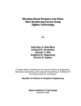
USB DOOR LOCK USING FINGERPRINT
BIOMETRICS TECHNOLOGY
by
Jonnavel A. Lerit
Jan Alfred Patrick R. Torres
A Design Report Submitted to the School of Electrical Engineering,
Electronics Engineering, and Computer Engineering in Partial
Fulfilment of the Requirements for the Degree
Bachelor of Science in Computer Engineering
Mapua Institute of Technology
January 2012
ii
ACKNOWLEDGEMENT
This design study would not have been possible without the guidance and
the help of several individuals who in one way or another contributed and
extended their valuable assistance in the preparation and completion of this
study. We would like to extend our sincere thanks to all of them.
Our sincerest gratitude goes to our design study adviser Engr. Ernesto M.
Vergara Jr., whose guidance and constant supervision has helped refine our
work.
Engr. Ayra G. Panganiban, our design instructor is highly appreciated who
until the completion of our design project had kind concern and consideration
regarding our academic requirements.
Ms. Gloria P. Cahulogan, the property manager of Casa Consuelo
Dormitory owned by Chloe Realty Corporation is likewise acknowledged for
accepting our design proposal and approving to be the customer of our design
study.
We would also like to express our gratitude towards our families, friends,
and colleagues for their utmost cooperation which inspired us in the completion
of this project.
Above all, we thank the Almighty God who gave us the knowledge,
strength, patience, perseverance, and courage in completing this design project.
iii
ROLES AND RESPONSIBILITIES OF MEMBERS
Role
Lerit, Jonnavel A.
The person responsible for designing and
developing the prototype
Responsibilities
Search for the equipment that can be used for the prototype
Analyzed the interfacing of the fingerprint reader and the USB
host device
Provides the algorithm to be used in storing the data
Finalize the design prototype
Role
Torres, Jan Alfred Patrick R.
The person responsible for coding and
testing the finished design prototype
Responsibilities
Code how the user will be able to store fingerprint in the
fingerprint device
Test the interaction of the fingerprint reading device and the USB
host device
Document the progress of the work
iv
TABLE OF CONTENTS
TITLE PAGE
i
APPROVAL SHEET
ii
ACKNOWLEDGEMENT
iii
ROLES AND RESPONIBILITIES OF GROUP MEMBERS
iv
TABLE OF CONTENTS
v
LIST OF TABLES
vii
LIST OF FIGURES
viii
ABSTRACT
ix
Chapter 1: DESIGN BACKGROUND AND INTRODUCTION
1
Background
1
Customer
1
Need
2
Solution
2
Objectives
3
Constraints
3
Impact
4
Differentiation
4
Benefits
5
Definition of Terms
6
Chapter 2: REVIEW OF RELATED DESIGN LITERATURES AND STUDIES
9
Biometrics
9
Fingerprint Reader
12
Pic-based Door Lock System
14
v
PC Interfaced Lock using Flash Drive as a Key
Chapter 3: DESIGN PROCEDURES
15
16
Hardware Development
19
Schematic Diagram
17
Software Development
21
Prototype Development
25
Chapter 4: TESTING, PRESENTATION, AND INTERPRETATION OF DATA
31
Chapter 5: CONCLUSION AND RECOMMENDATION
39
BIBLIOGRAPHY
41
APPENDIX
43
Appendix A: Operation’s Manual
43
Appendix B: Pictures of Prototype
46
Appendix C: Datasheets
49
Appendix D: Others (Program Listing)
69
vi
LIST OF TABLES
Table 2-1: Comparison of Several Biometric Technologies
10
Table 2-2: Comparison of Various biometric technologies
11
Table 3-1: Component Price Listing
30
Table 4-1: Verify Enrolled Fingerprint
32
Table 4-2: Verify Not Enrolled Fingerprint
34
Table 4-3: Enroll New Fingerprint
36
vii
LIST OF FIGURES
Figure 2-1
Various Biometrics Technologies
9
Figure 2-2
Minutia extraction
13
Figure 2-3
System diagrams of door lock controller programming module
14
Figure 3-1
Block Diagram
16
Figure 3-2
Schematic Diagram – USB Door Lock using Biometrics
Fingerprint Technology
17
Figure 3-3
Door Access Flow Chart of Enrolled and Not enrolled users
21
Figure 3-4
Door Access Flow Chart with Administrator Rights
22
Figure 3-5
USB Host Kit
26
Figure 3-6
Biometric Fingerprint Reader
25
Figure 3-7
Microcontroller Unit
26
Figure 3-8
Relay Module
26
Figure 3-9
Universal Serial Bus
27
Figure 3-10 Solenoid
27
Figure 3-11 Switch
28
Figure 3-12 Resistor
28
Figure 3-13 Connecting Wire
29
viii
ABSTRACT
The USB Door Lock using Biometrics Fingerprint Technology aims to interface a
bio-metric reader, specifically a fingerprint scanner, and a door lock using a USB
port that will secure a specific room. This device can be a replacement for keys
and cards. The design is composed of the USB interfaced fingerprint reading
device and a circuit to trigger the locking and unlocking of the door. Pic BASIC is
used in the programming of the microcontroller unit to interact with the
fingerprint reader in triggering relays for locking and unlocking of the door. With
this system, securing access to establishments is guaranteed while providing
convenience and efficiency in entering a room.
Keywords: Biometrics, USB, Microcontroller unit, Relay, Pic BASIC
ix
Chapter 1
DESIGN BACKGROUND AND INTRODUCTION
Introduction
Technology is developed by people to help improve the quality of human
lives, and all are using technological advances in many different ways and one of
these ways is security system. When it comes to security systems, biometrics is
one of the top of the choices which has brought significant changes with regards
to how people gain access of rooms or establishments. The use of biometrics
have changed the security system from what people conventionally used such as
passwords or what a person possesses such as door keys to something a person
embodies such as retinal patterns, fingerprints, or voice recognition. Fingerprint
recognition is one of the most popular and successful methods used for person
identification, which takes advantage of the fact that the fingerprint has some
unique characteristics called minutiae; which are points where a curve track
finishes, intersect with other track or branches off (Aguilar et. al., 2007).
In this design project the conventional mechanical door lock that uses
metal keys is replaced with a USB door lock with fingerprint authentication using
a separate fingerprint reading device for the user that will serve as the key.
Customer
The target customer of this design project is Casa Consuelo Dormitory
owned by Realty Corporation and one of the competing dormitories residing
1
inside Intramuros, specifically located at Lot 3 Block 41 Solana St. Intramuros,
Manila. Casa Consuelo is one of many that offer affordable rooms and a secured
living for its tenants.
Need
Secured rooms are important to Casa Consuelo in gaining trust from its
future and existing tenants. But with several cases of theft, there is a need for
better security measures within the premises of the dormitory. That is the reason
why Casa Consuelo is looking to improve their existing security system of just the
conventional door locks and replace is with a systems that would ensure access
to be only entitled to the occupants of each room.
Solution
With the need to replace or improve the existing security system of Casa
Consuelo Dormitory in its rooms, the researchers come up with the solution of
replacing the conventional door lock with a USB Door Lock accessed using a
separate fingerprint reading device that serves as the key. The proposed system
will replace the existing system with an innovative new system in such a way the
tenants can gain access using USB communication between the separate
fingerprint reading device and the door lock that validates the captured
fingerprint. This will ensure only tenants occupying the specific room can gain
access prohibiting unauthorized access to the room by other tenants, guests and
even the administrators of the dormitory.
2
Objectives
Aside from aiding the need of Casa Consuelo Dormitory in improving their
rooms’ security system and resolve problems of theft, this design projects also
aims to create a USB door lock system with the same principle of a door lock and
a key with the use of a separate fingerprint reading device. The researchers also
aim that the USB door lock using biometrics fingerprint technology is reliable in
validating fingerprints in accordance to the proper placement of the fingerprint to
the scanner to gain access of the door and also the addition and deletion of
fingerprints to the system.
Constraints
In using biometrics fingerprint technology, there are studies showing that
among the different biometrics, fingerprint authentication is one of the top if not
the top choice to be used for identification systems of devices. Although these
studies showed the benefits and competencies in using different kind of
biometrics, the limiting factor for this design project in using biometrics
fingerprint technology is the acceptance of the society with fingerprint
authentication. Socially, people nature does not shift to a newly introduced
system quickly. That is why the group’s implementation of the USB door lock
using fingerprint biometric technology started with a dormitory as its client. This
is not just to solve the theft problems within the dormitory and improve their
security system, but also the implementation of a system using biometrics for
authentication showing and focusing the benefits it can give.
3
Impact
With
the
advancement
of
technology,
the
society
is
becoming
electronically connected to form one big global community. Surrogate
representations of identity such as passwords and key cards no longer suffice
making biometrics as one of the choice of form of security.
This design may further improve the security system of the dormitory and
will also have an impact with the people’s safety, security to be more specific.
This is in terms of aiding the target customer’s need of improving its rooms’
security system in implementing a USB door lock with a separate fingerprint
reading device for fingerprint authentication in gaining access that is only
entitled to the occupants of the room. The design solution is also not comprised
of harmful material that may affect the environment where the system is
installed.
Differentiation
This design project is unique as it did not completely throw away the use
of keys when dealing with door locks as it uses a separate USB fingerprint
reading device from the USB door lock. The fingerprint reading device and the
door lock communicates via a USB port placed at the door. The project also
provides
functions
such
as
the
addition,
deletion,
and
verification
(authenticating) of the user/owner of the room/unit. In existing USB door locks,
some were needed to be interfaced with a personal computer (PC) when
authenticating users, the use of keypads for personal PINS were implemented,
4
and others were using the serial number of a flash drive. In term with technology
used, this design project utilizes fingerprint technology and won’t be needing to
be interfaced with a PC in authenticating users or even during the addition and
deletion of fingerprints. This project also features just having the USB port
outside the door making it for other people to distinguish what security system it
uses.
Benefits
Biometrics has brought significant changes in security systems making
them more secure than before, efficient, and cheap. The target customer being
a dormitory can earn trust from their existing and future occupants with the
implementation of this design project featuring the an improved way of
eliminating unauthorized access with the use of fingerprint biometrics providing
the needed improvement on each room’s security system.
5
Definition of Terms
1.
Biometrics - consists of methods for uniquely recognizing humans based
upon one or more intrinsic physical or behavioral traits. It is used as a
form of identity access management and access control. It is also used to
identify individuals in groups that are under surveillance.
2.
Fingerprint - an impression left by the friction ridges of a human finger.
It is the trace of an impression from the friction ridges of any part of a
human hand.
3.
USB(Universal Serial Bus) - an industry standard developed in the mid1990s that defines the cables, connectors and communications protocols
used in a bus for connection, communication and power supply between
computers and electronic devices. USB was designed to standardize the
connection of computer peripherals, such as keyboards, pointing devices,
digital cameras, printers, portable media players, disk drives and network
adapters to personal computers, both to communicate and to supply
electric power.
4.
Minutiae - major features of a fingerprint, using which comparisons of
one print with another can be made. Minutiae include:
Ridge ending – the abrupt end of a ridge
Ridge bifurcation – a single ridge that divides into two ridges
Island – a single small ridge inside a short ridge or ridge ending
that is not connected to all other ridges
6
Ridge enclosure – a single ridge that bifurcates and reunites
shortly afterward to continue as a single ridge
Spur – a bifurcation with a short ridge branching off a longer ridge
Crossover or bridge – a short ridge that runs between two
parallel ridges
5.
Failure to Enroll Rate (FTE or FER) - the rate of performance of
biometric systems at which attempts to create a template from an input is
unsuccessful. This is most commonly caused by low quality inputs.
6.
Failure to Capture Rate (FTC) - within automatic systems, the
probability that the system fails to detect a biometric input when
presented correctly.
7.
Fingerprint Reader – the device used to read/scan and store the
fingerprint of a certain user
8.
Fingerprint Identification - also known as dactyloscopy, or hand print
identification, is the process of comparing two instances of friction ridge
skin impressions, from human fingers, the palm of the hand or even toes,
to determine whether these impressions could have come from the same
individual.
9.
Fingerprint Authentication - refers to the automated method of
verifying a match between two human fingerprints. Fingerprints are one
of many forms of biometrics used to identify individuals and verify their
identity.
7
10.
Fingerprint Verification - the comparison of a claimant fingerprint
against an enrollee fingerprint, where the intention is that the claimant
fingerprint matches the enrollee fingerprint. To prepare for verification, a
person initially enrolls his or her fingerprint into the verification system. A
representation of that fingerprint is stored in some compressed format
along with the person’s name or other identity.
8
Chapter 2
REVIEW OF RELATED DESIGN LITERATURES AND STUDIES
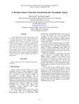
BIOMETRICS
In the article entitled “Biometrics”, written by Dilum Bandara, a PhD
Candidate in the Computer Networking Research Laboratory, Department of
Electrical and Computer Engineering, Colorado State University, USA (2008),
defined Biometrics as an open-minded set of technologies based on the
measurement of some unique physical characteristics of an individual for the
purpose of identifying an individual or verifying identity which cannot be
borrowed, stolen, or forgotten. This technology measures the individual’s unique
physical or behavioural characteristics to recognize or authenticate their identity.
Behavioural characteristics include signature, signature dynamics, voice, lip
movement, keystroke analysis, and gait. Physical characteristics include hand
geometry, retina, iris, facial characteristics and fingerprints.
Figure 2-1 Various Biometrics Technologies
In another article entitled “Biometric Recognition: Security and Privacy
Concerns” by Prabhakar, Pankanti and Jain (2003) described biometrics systems
9
is essentially a pattern-recognition system that recognizes a person based on a
feature vector derived from a specific characteristic that a person possesses. And
typically operates in one of two modes: verification, validating a person’s identity
by comparing the captured biometric characteristics with the individual’s
biometric template, or identification, recognizing an individual by searching the
entire template database for a match.
Several biometric characteristics can be used in various applications. Each
biometric has its strengths and weaknesses, and choosing the best characteristic
to use depends on the application as no single biometric can effectively meet
every requirements – none is “optimal”.
Table 2-1 Comparison of several biometric technologies
Table 2-1 shows the comparison of several biometrics conducted by the
researchers of the article “Biometric Recognition: Security and Privacy Concerns”,
(2003). Ranking each characteristic based on the given categories as being low,
medium or high. A low category indicates poor performance in the evaluation
10
criterion, whereas a high ranking category indicates a very good performance.
The following parameters are used: barriers to universality, distinctiveness,
permanence,
collectability,
performance,
acceptability,
potential
for
circumvention.
Table 2-2 Comparison of Various biometric technologies
Also in a study by A.K. Jain, biometrics was ranked as shown in Table 2.2
using the parameters: universality, uniqueness, permanence, collectability,
performance, acceptability, circumvention.
Analysing the comparisons, a biometric device that uses fingerprints
shows more pleasing results. Also, its cost and portability are big factors why
fingerprints have an edge over the other biometrics. A fingerprint scanner can be
easily installed and utilized by an application and it is also very much acceptable
in the industry.
Biometrics is a rapidly evolving technology widely used in forensics than
access control. In a study done by A.K. Jain, S. Pankanti, S. Prabhakar, L. Hong,
11
and A. Ross, the “Biometrics: A Grand Challenge”, the researchers cited that as
our society becomes electronically connected to form one big global community,
it has become necessary to carry out reliable person identification often remotely
and through automatic means. Surrogate representations of identity such as
passwords (prevalent in electronic access control) and cards (prevalent in
banking and government applications) no longer suffice. Further, passwords and
cards can be shared and thus, cannot provide non-repudiation. Furthermore, the
researchers concluded that existing biometric technology should not be
construed that it is not useful. In fact, there are a large number of biometric
solutions that have been successfully deployed to provide useful value in
practical applications.
FINGERPRINT READER
Fingerprint is one of the most common biometrics used in the field of
security which still faces unique challenges for acceptance especially the threat
of identity theft which has been validated as a realistic vulnerability. And in the
study by S. Palka and B. A. Hamilton in the “Fingerprint Readers: Vulnerabilities
to Front- and Back- end Attacks”, the researchers stated that the technology
used for sensors and fingerprint processing has matured but vulnerabilities still
persist described in their paper.
12
Figure 2-2 Minutia extraction: (a) good quality input image; (b) extracted
minutiae; (c) poor quality input image; (d) extracted minutiae.
An automatic fingerprint identification system (AFIS) is based on a
comparison of minute details of ridge/valley structures of fingerprints. A total of
eighteen different types of local ridge/valley descriptions have been identified.
Among them, ridge endings and ridge bifurcations (Figure 2-2(a)), which are
usually called minutiae, are the two most prominent structures used in an
automatic fingerprint identification system.
Prevention of identity theft is done by encrypting the biometric data
gathered. After the identification of specific points of data, the match points in
the database were processed using an algorithm that translates that information
into a numeric value. The database value was then compared with the biometric
input where the authentication is either approved or denied.
13
PIC-BASED DOOR LOCK SYSTEM
Figure 2-3 System diagrams of door lock controller and programming modules
The Microprocessor-controlled door lock system done by D. C. Poirier and
S. R. Vishnubhotla, (March 1990), pointed out that maintaining an entry only to
authorized persons for multi-dwelling buildings such as apartments, dormitories,
etc. is a problem. The system is composed of two modules, the door lock
controller board and the programming board shown in Figure 2-3.
In another study by A. Bitoon, et. Al (September 2003) regarding a PICbased door lock system, the researchers stated that; “PIC-based door lock
system provides a means of replacing old fashioned locks using keys by means
of sensors and readers. With this PIC-based door lock system provides a means
of replacing old fashioned locks using keys by means of sensors and readers.
With this door lock system homes and establishments can avail of better safety
and security. It uses components such as a keypad for password input and
Programmable Integrated Circuit Microcontroller as to control the functions of
the system.”
14
Based on these studies, researchers learned that microcontrollers can also
be used for locking and unlocking doors for better safety and security. Based on
an article published in Blackheath, South Africa in 2006, Biometric locks provide a
more secured access to homes as well as the easiest way to enter an
establishment. Moreover, static pins will no longer be needed for a hassle free
access to a room.
PC INTERFACED LOCK USING FLASH DRIVE AS A KEY
With the use of a USB flash drive as an alternative key for door lock, M.
Balmes, et. Al (July 2009), developed a PC Interfaced Lock using Flash Drive as a
Key. Using a microcontroller, a PC and with the storing capability of a flash drive,
a data corresponding to its assigned room is stored and the software will validate
as soon as the user inserted the flash drive. In this study, the researchers stated
that, “PC Interfaced Lock using Flash Drive as a Key is a device that will replace
the usual key the people are using with a USB Flash Drive”.
In an article entitled “USB Auth”, a project demonstrated a computerized
door lock that reads the unique ID of the USB Flash Drive to gain access. This
project also uses a USB as its access port and with the unique serial number of a
flash drive, the PC will check if the device is on the approved list to instruct the
servo to unlock the door.
With these studies, replacing a conventional door locks key is possible
using USB connection between a USB flash drive and the door lock.
15
Chapter 3
DESIGN PROCEDURES
HARDWARE DEVELOPMENT
BLOCK DIAGRAM
FINGERPRINT
SENSOR
INPUT
MEMORY
MICROCONTROLLER
MAGNETIC
LOCK
Figure 3-1 Block Diagram of the Design
The block diagram serving as the backbone of the design and figure 3-1
illustrates the block diagram used by the group. There is the Fingerprint Sensor
that will wait for an input which is a fingerprint, after receiving an input the
Fingerprint Sensor will then send signal to the microcontroller unit. The
microcontroller unit will then pass the signal to the memory. After the memory
validates the data sent to it, the memory will send back an answer to the
microcontroller which will determine if the magnetic lock should open the door or
not.
16
SCHEMATIC DIAGRAM
Figure 3-2 Schematic Diagram – USB Door Lock using Biometrics Fingerprint Technology
17
Figure 3-2 shows the schematic diagram of the USB Door Lock using
Biometrics Fingerprint Technology. The schematic diagram is divided into three
systems which are the USB Door Lock, Relay, and the Fingerprint Reading
Device. The USB Door Lock system is the main system that is placed in the door
and needs the Fingerprint Reading Device to be activated.
For the USB Door Lock system, from a 220V AC it will be regulated to 12V
to be able to comply with the operating state of the PIC168F77A microcontroller
unit. The operating state of the microcontroller is as referenced from its
datasheet. A 470 micro-Farad capacitor is connected to the output voltage of the
regulator and the ground to filter out the noise coming from the regulator.
The relay driver circuit is responsible for controlling the AC power used by
the USB Door Lock system which consists of a PNP-transistor, 22 kilo-Ω resistor,
12V relay and 1N4006 diode. The 22kilo-Ω resistor allows small current to pass
through the base-emitter junction. The output lines of the relay circuit are then
connected to the output port RC5 of PIC168F77A, and to the 1N4006 diode and
is connected to the 12V output of the regulator of door lock system and lastly it
is connected to the ground. The transistor serves as a circuit that controls the
state of the relay. When a small positive volt (3.3V) was applied at the base of
the transistor, the collector-emitter junction connects together. Thus, the 12V
power flows through the inductor part of the relay which then energizes the
switch inside the relay. The state of the switch determines if the AC power flow
to the AC socket. The reverse-biased diode serves as a voltage protection for the
18
inductor part of the relay such that no current will pass through when the
transistor is not active. If ever no positive voltage is applied to the base of the
transistor, the transistor will not be in active state and the AC power is
disconnected to the AC socket.
The fingerprint reading device is the one responsible for collecting user’s
fingerprints. It is regulated by a 5V output voltage. An oscillator of 20 megaHertz is connected to one of the microcontroller’s pin for the purpose of timing
frequency.
The formula used in getting the value of the capacitor in the relay circuit is:
C=
=
= 33.29 pF
Where:
C= computed capacitance in farads (F),
I = measured output current from the supply in amps (A),
V = measured supply voltage in volts (V),
f = frequency of the AC supply in hertz (Hz)
The base resistor of each transistor circuit is obtained using the formula:
Rb =
=
=22.02kΩ
Where:
19
Rb = computed base resistor in ohms
Vb = the base voltage in volts (V)
Vbe = the difference from the base voltage to the base emitter
Ib = measured base current in amperes (A)
20
SOFTWARE DEVELOPMENT
PROGRAM FLOW CHART
Start
No
A
Wait for a request from
the fingerprint device
B
Is there a
request from
the fingerprint
device
B
Compare the scanned
fingerprint to the
fingerprint database
No
Is there a
match
Yes
Yes
Wait for a reading
coming from the
fingerprint device
Door Open and buzzer
sounds
End
No
Is a reading
from the
fingerprint
device present
Yes
A
21
Figure 3-3 Door Access Flow Chart of Enrolled and Not enrolled users
Start
C
Wait for a request from
the fingerprint device
No
Enable add and delete
functions
D
Is there a
request from
the fingerprint
device
Delete
Yes
Capture
Fingerprint
Fingerprint
Yes
Delete captured
fingerprint
No
Verify Fingerprint
Add
Fingerprint
Capture
Fingerprint
Add captured
fingerprint
C
Request Timeout
D
End
Figure 3-4 Door Access Flow with Administrator Rights
22
The following figures, referring to figure 3-3 and figure 3-4, are the flow
charts of the prototype being design. It shows the processes of the verification
and enrolment features of the USB Door Lock System using Biometrics
Fingerprint Technology. The system starts up as soon as it is plugged in and
immediately initializes all the variables needed to clear unwanted data that may
cause system failure. The system also waits for the request from the fingerprint
reading device before making any actions in which verification of fingerprint is
always the first thing to do. Whether the user wants to open the door or enroll a
new fingerprint, the system will always verify first if the requesting user’s
fingerprint is enrolled. Unlocking the door just requires the user to verify itself
and as soon as the system recognizes that the requesting user’s fingerprint is
enrolled, the door lock will open and immediately sound the buzzer prompting
that the door is open signifying that the door is open for attacks and must be
close to activate the locking system again. The enroll feature happens only when
the user is inside the room or establishment, assuming the requesting user’s
fingerprint is indeed enrolled in the system. After verification of the user’s
fingerprint, the system will prompt that the user is logged in and the enroll
feature is now enabled. Upon enrolment, it will again verify the fingerprint to be
enrolled by capturing three samples of the fingerprint and add it into the system
prompting the fingerprint number for both the door lock system and the
fingerprint device.
23
The system was made possible with the use of Maxis Biometrics SM630
fingerprint module equipped with an optical fingerprint sensor, high performance
DSP processor and Flash and can perform fingerprint deletion, fingerprint
verification and fingerprint addition. The SM630 module algorithm was specially
designed according to the image generation theory of the optical fingerprint
collection device which has excellent correction and tolerance to deformed and
poor-quality fingerprint. In which fingerprint recognition or authentication’s two
major classes of algorithms, minutia and pattern, was used together with the
optical sensor. Optical sensor imaging involves capturing a digital image using
visible light when the finger is placed in the touch surface where beneath that
surface is a light-emitting phosphor layer responsible in illuminating the surface
of the finger and when the light reflected from the finger passes through the
phosphor layer to an array of solid state pixels that captures a visual image of
the fingerprint.
Fingerprint matching is key for this design to be operational and matching
algorithms are used to compare previously stored templates of fingerprint
against candidate fingerprints for authentication purposes. The pattern-based or
image-based algorithms compare the basic fingerprint patterns such as the arch,
whorl and loop between a previously stored template and a candidate
fingerprint. For this algorithm to work properly, it requires that the images must
be aligned in the same orientation and doing this, the algorithm finds a central
point in the fingerprint image. With this algorithm, the template contains the
24
type, size, and orientation of patterns within the aligned fingerprint image. Thus,
the candidate fingerprint image is graphically compared with the template to
determine the degree to which they match.
PROTOTYPE DEVELOPMENT
Figure 3-5 USB Host Kit
The VNC2 USB Host kit with a preloaded Vinculum Disk and Peripherals
firmware enables the researchers to incorporate USB host functions and interface
it with a host microcontroller which enables the prototype to communicate
through a universal serial bus.
Figure 3-6 Biometric Fingerprint Reader
25
The biometric fingerprint reader serves as the main device for the
verification of fingerprints and it has a DSP controller for easy integration with a
microcontroller unit.
Figure 3-7 Microcontroller Units
The microcontroller unit is in charge of receiving data from the VDIP USB
Host and also sends out signal to the relay to control the solenoid and buzzer
upon locking and unlocking of the door.
Figure 3-8 Relay Modules
The relay is used for triggering the state of a component in the device
which waits for the microcontroller unit to send a signal to the relay to activate a
26
component. This module would trigger the solenoid whether to open the door or
not.
Figure 3-9 Universal Serial Bus
Universal Serial Bus ports are used to accept request from the fingerprint
reading device and transfer it to the microcontroller unit. USB 2.0 connection is
used to allow simplified attachment of peripherals and cater the growing usage
of USB connection.
Figure 3-10 Solenoids
27
The solenoid is used as a lock for the door in the system. It is considered
as an output for the circuit as it waits a signal from the relay to latch its state.
Figure 3-11 Switches
The switches serve as the mode selector for both the system and the
fingerprint device. It enables the user to select whether to verify, add or delete a
fingerprint.
Figure 3-12 Resistors
Resistors are used for balancing the flow of current and are also used for
pull-ups to produce proper input going through the system.
28
Figure 3-13 Connecting Wire
The connecting wire serves as an extension to isolate and extend the range of
the components like the solenoid and the USB ports,
29
COMPONENT
PRICE (PHP)
QUANTITY
PRICE (PHP)
Fingerprint Reader
4500.00
1
4500.00
PIC1220
205.00
1
205.00
PIC16F877A
250.00
1
250.00
18 Pins IC Socket
7.00
1
7.00
20mHZ Crystal Oscillator
30.00
1
30.00
Push-on switch
15.00
4
60.00
2 Pins Connector
10.00
1
10.00
LCD
780.00
1
780.00
VDIP USB Host
798.00
1
798.00
Buzzer
30.00
1
30.00
Fingerprint Device Casing
35.00
1
35.00
Door Lock Casing
180.00
1
180.00
3A Transformer
375.00
1
375.00
750mA Transformer
175.00
1
175.00
Bridge Rectifier
30.00
1
30.00
Battery Holder
15.00
1
15.00
Magnetic Lock
1500.00
1
1500.00
0.1 Capacitor
5.00
2
10.00
Total
8990.00
Table 3-1 Component Price Listing
30
Chapter 4
TESTING, PRESENTATION, AND INTERPRETATION OF DATA
Functionality Test
The system can verify whether the scanned fingerprint is enrolled or not
and has add and delete fingerprint functions for registered fingerprints.
The
researchers tested the features of the USB door lock system: Verify and Enroll
fingerprints.
Procedure for the verification feature:
1. First, plug the system and make sure it is functioning properly without
errors seen in the LCD.
2. Turn on the fingerprint reading device.
3. Insert the device into the system.
4. Push the verify button and wait for the fingerprint scanner to light up.
5. Once the scanner lights up scan the fingerprint and wait if the door opens
or not.
6. Repeat step 3 every time a user access the door lock.
Procedure for the enrollment feature:
31
1. First, plug the system and make sure it is functioning properly without
errors seen in the LCD.
2. Turn on the fingerprint reading device.
3. Make sure you are inside the room or establishment then insert the device
into the system.
4. Push the verify button in the system and in the device, respectively, and
wait for the fingerprint scanner to light up.
5. Once the scanner lights up scan the fingerprint and wait if the LCD
indicates that the user is logged in.
6. Push the add button and wait until the device lights up.
7. Scan the new fingerprint thrice and wait until the LCD indicates the
fingerprint number for both the system and the fingerprint reading device.
8. Repeat step 3 every time new a user or fingerprint is to be enrolled.
The following tables illustrate how the features of the USB Door Lock
System must be tested to ensure all functionalities are working properly.
TRIAL
VERIFICATION
STATUS
1
VERIFIED
UNLOCKED
2
VERIFIED
UNLOCKED
3
VERIFIED
UNLOCKED
32
4
VERIFIED
UNLOCKED
5
VERIFIED
UNLOCKED
6
VERIFIED
UNLOCKED
7
VERIFIED
UNLOCKED
8
VERIFIED
UNLOCKED
9
NOT VERIFIED
LOCKED
10
NOT VERIFIED
LOCKED
11
NOT VERIFIED
LOCKED
12
VERIFIED
UNLOCKED
13
VERIFIED
UNLOCKED
14
VERIFIED
UNLOCKED
15
VERIFIED
UNLOCKED
16
VERIFIED
UNLOCKED
17
VERIFIED
UNLOCKED
18
VERIFIED
UNLOCKED
19
VERIFIED
UNLOCKED
20
NOT VERIFIED
LOCKED
21
NOT VERIFIED
LOCKED
22
VERIFIED
UNLOCKED
23
VERIFIED
UNLOCKED
24
VERIFIED
UNLOCKED
33
25
VERIFIED
UNLOCKED
26
NOT VERIFIED
LOCKED
27
VERIFIED
UNLOCKED
28
VERIFIED
UNLOCKED
29
VERIFIED
UNLOCKED
30
VERIFIED
UNLOCKED
Table 4-1 Verify Enrolled Fingerprint
Based on the results, the USB Door Lock System design prototype
accurately verifies if the captured or scanned fingerprint in enrolled or not in the
database. There were some instances that even if the finger is enrolled, the
system won’t unlock the door since the verification depends on how that specific
finger was scanned during its enrollement to the system as the fingerprint
reading gathers three samples of scanned fingerprint template for accuracy in
which the researchers consider misplacement of fingerprint into the fingerprint
reader as the cause of the problem.
TRIAL
VERIFICATION
STATUS
1
NOT ENROLLED
LOCKED
2
NOT ENROLLED
LOCKED
3
NOT ENROLLED
LOCKED
4
NOT ENROLLED
LOCKED
34
5
NOT ENROLLED
LOCKED
6
NOT ENROLLED
LOCKED
7
NOT ENROLLED
LOCKED
8
NOT ENROLLED
LOCKED
9
NOT ENROLLED
LOCKED
10
NOT ENROLLED
LOCKED
11
NOT ENROLLED
LOCKED
12
NOT ENROLLED
LOCKED
13
NOT ENROLLED
LOCKED
14
NOT ENROLLED
LOCKED
15
NOT ENROLLED
LOCKED
16
NOT ENROLLED
LOCKED
17
NOT ENROLLED
LOCKED
18
NOT ENROLLED
LOCKED
19
NOT ENROLLED
LOCKED
20
NOT ENROLLED
LOCKED
21
NOT ENROLLED
LOCKED
22
NOT ENROLLED
LOCKED
23
NOT ENROLLED
LOCKED
24
NOT ENROLLED
LOCKED
25
NOT ENROLLED
LOCKED
35
26
NOT VERIFIED
LOCKED
27
NOT VERIFIED
LOCKED
28
NOT VERIFIED
LOCKED
29
NOT VERIFIED
LOCKED
30
NOT VERIFIED
LOCKED
Table 4-2 Verify Not Enrolled Fingerprint
Based on the results for the verification of not enrolled fingerprints, the
USB door lock system design prototype accurately verify that the captured or
scanned fingerprint is not in the memory or enrolled into the system. This proves
that the design can secure places where it will be installed with 100% accuracy
in verifying intruders or untrusted access.
TRIAL
MODE
STATUS
1
ADD TEMPLATE
ENROLLED
2
ADD TEMPLATE
ENROLLED
3
ADD TEMPLATE
ENROLLED
4
ADD TEMPLATE
ENROLLED
5
ADD TEMPLATE
ENROLLED
6
ADD TEMPLATE
ENROLLED
7
ADD TEMPLATE
ENROLLED
8
ADD TEMPLATE
ENROLLED
9
ADD TEMPLATE
ENROLLED
36
10
ADD TEMPLATE
ENROLLED
11
ADD TEMPLATE
ENROLLED
12
ADD TEMPLATE
ENROLLED
13
ADD TEMPLATE
ENROLLED
14
ADD TEMPLATE
ENROLLED
15
ADD TEMPLATE
ENROLLED
16
ADD TEMPLATE
ENROLLED
17
ADD TEMPLATE
ENROLLED
18
ADD TEMPLATE
ENROLLED
19
ADD TEMPLATE
ENROLLED
20
ADD TEMPLATE
ENROLLED
21
ADD TEMPLATE
ENROLLED
22
ADD TEMPLATE
ENROLLED
23
ADD TEMPLATE
ENROLLED
24
ADD TEMPLATE
ENROLLED
25
ADD TEMPLATE
ENROLLED
26
ADD TEMPLATE
ENROLLED
27
ADD TEMPLATE
ENROLLED
28
ADD TEMPLATE
ENROLLED
29
ADD TEMPLATE
ENROLLED
30
ADD TEMPLATE
ENROLLED
Table 4-3 Enroll New Fingerprint
37
Based on the gathered data for enrolling a new fingerprint template into
the system, new fingerprints can be accurately enrolled into the system given
that the user has admins rights the user’s fingerprint is already enrolled where
testing results for verifying enrolled fingerprints are shown in Table 4-1.
Impact Analysis
This design may further improve the security system of the dormitory and
will also have an impact with the people’s safety, security to be more specific.
This is in terms of aiding the target customer’s need of improving its rooms’
security system in implementing a USB door lock with a separate fingerprint
reading device for fingerprint authentication in gaining access that is only
entitled to the occupants of the room. The design solution is also not comprised
of harmful material that may affect the environment where the system is
installed.
38
Chapter 5
CONCLUSION AND RECOMMENDATION
Conclusion
There is a lot of existing door locks using biometric fingerprint technology
and most of them integrate the fingerprint device into the door lock itself. In
which the researchers of this USB Door lock separates the fingerprint reading
device and preserving the principle of having a tangible device to be used as the
key. This paper also achieved its objective that a fingerprint reader and a
microcontroller controlled door lock can be interfaced to use USB as its main
connection. This design also proves that it can improve the level of security of
establishments using the mechanical door locks through the uniqueness each
person’s fingerprint. The testing process proves that the system can accurately
identify and compare fingerprint templates at a high rate whether it is to enrol a
new fingerprint template or just verify if the captured template is in the memory
or already enrolled. Through the use of this design, people will have an easier
way of having a convenient, secured, and authorized entrance in a certain room
or establishment as there would be no keys, passwords or cards will be used.
Owners would just register trusted fingerprints that could enter its premises.
With this system, it can automate door locks and help people especially security
guards and utility men, administrators and owners to secure its premises.
39
Recommendation
This design project can be further improved through a more intensive
development and additional features. The design aims to prove that USB door
locks using biometrics fingerprint technology can accurately verify users and
secure places.
First, further studies can improve the source of power especially the
fingerprint reading device as it is for now battery operated. Another
improvement is providing the main owner to have the capability to delete users
without the verification of their fingerprints. It is also recommended to have an
override button inside the room or establishment for a more convenient way of
going out of the place. In addition, the researchers recommend having a delete
all except the main owner in case the fingerprint numbering is messed up. Also,
an additional feature of having a keypad for proper identification of the
fingerprints being stored which can be a preparation in case the main owners
have the capability to delete fingerprints without the verification or consent of
the user’s fingerprint being deleted. Additional recommendations would be
utilizing a larger memory and an additional timer for dormitories with curfew
hours which would disable and enable door access.
Lastly, the researchers would like to recommend reducing the size of the
devices most especially the fingerprint reading device. This is to improve
portability and also additional security.
40
BIBLIOGRAPHY
H.M.N. Dilum Bandara (2008). Biometrics
Salil Prabhakar, Sharath Pankanti, Anil K. Jain (2003). Biometric Recognition:
Security and Privacy Concerns
Anil K. Jain, Sharath Pankanti, Salil Prabhakar, Lin Hong, Arun Ross.
Biometrics: A Grand Challenge
Sean Palka, Booz Allen Hamilton, Harry Wechsler (2007). Fingerprint
Readers: Vulnerabilities to Front- and Back-end Attacks
David C. Poirier, Sarma R. Vishnubhotla (1990). A Microprocessor-Controlled
Door Lock System
Araneta, A., Bitoon, J., Cabatana, C., Cane, F., Quinones, J., Repollo, E.
(2003). PIC-Based Door Lock System
Eliseo G. Noble Jr, Jean Eric V. Agena, Jon Remon D. Loon, Judy Ann U.
Rodriguez, Karl Lester A. Co (2003). Automated Finger Print Activated
Door Lock
Maryola M. Balmes, John Henji O. Mantaring, Kammier G. Maraya, Mary
Grace M. Montivirgen, Mark Joseph D. Paderal (2009). PC Interfaced
Lock using Flash Drive as a Key
41
Makers Local 256. (2010). USB Auth. Retrieved August 14, 2011 from
https://256.makerslocal.org/wiki/index.php/USB_Auth#External_Links
Guodong Li, Hu Chen (2010). A New High-Level Security Potable System
based on USB Key with Fingerprint
Anil K. Jain, Arun Ross, Salil Prabhakur (2003). An introduction to Biometric
Recognition
Shimon K. Modi, Stephen J. Elliott, Jeff Whetsone, Hakil Kim (2007). Impact
of Age Groups on Fingerprint Recognition Performance
42
APPENDIX
A. OPERATION’S MANUAL
1. SYSTEM REQUIREMENTS
The “USB DOOR LOCK USING BIOMETRICS FINGERPRINT TECHNOLOGY”
only works if the door lock system and the fingerprint reading device is
turned on and the device communicates with the system through inserting
it into the USB port.
2. INSTALLATION PROCEDURE
The following procedures must be followed to ensure the system works
properly.
Turning on the door lock system:
1. Plug the system into an outlet.
2. Make sure the LCD displays no error.
Inserting the fingerprint reading device:
1. Make sure there is a battery is connected into the device.
2. Push the button to start up the device. Never turn on the device while
it is inserted into the door lock system.
3. Wait until the blinking light stops.
4. Insert the device into the door lock system.
43
3. USER’S MANUAL
3.1
Plug the system into an outlet.
3.2
Make sure the LCD displays no error.
3.3
Make sure there a battery is connected into the fingerprint device.
3.4
Push the button to start up the device.
3.5
Wait until the blinking light stops.
3.6
Insert the device into the door lock system.
3.7
Push the verify button to access the door lock.
3.8
Wait until the fingerprint scanner lights up.
3.9
Place the fingerprint properly into the scanning glass.
3.10
Finish the verification and check if the door unlocks.
4. TROUBLESHOOTING GUIDES AND PROCEDURES
4.1 After turning the door lock system, check if the LCD displays an error.
If yes, re-plugged the door lock system until the LCD indicates that the
system is working properly
4.2 After switching on the fingerprint reading device, check if the LED
lights up and blink three times. If not, push off the power button and
power it on again.
44
5. ERROR DEFINITIONS
5.1 Door lock system LCD displays and error – there is a problem during
the initialization of the VDIP USB Host
5.2 Fingerprint reading device LED does not light up – there is a problem
with the push button upon triggering the device to operate
45
B. PICTURES OF PROTOTYPE
46
47
48
C. DATA SHEETS
49
50
51
52
53
54
55
56
57
58
59
60
61
62
63
64
65
66
67
68
D. OTHERS (Program Listing)
Fingerprint Reading Device
'Transmitter Module
Device 18F1220
Declare Xtal 20
Config_Start
OSC = HS
; XT 4MHz
FSCM = On
; Fail-Safe Clock Monitor enabled
IESO = On
; Internal External Switch Over mode enabled
PWRT = OFF
; Disabled
BOR = OFF
; Disabled
WDT = OFF
; Disabled
WDTPS = 32768
; 1:32768
MCLRE = OFF
; Disabled
STVR = On
; Enabled
LVP = OFF
; Disabled
Debug = OFF
; Disabled
CP0 = OFF
; Disabled
CP1 = OFF
; Disabled
CPB = OFF
; Disabled
CPD = OFF
; Disabled
WRT0 = OFF
; Disabled
WRT1 = OFF
; Disabled
WRTB = OFF
; Disabled
WRTC = OFF
; Disabled
WRTD = OFF
; Disabled
EBTR0 = OFF
; Disabled
EBTR1 = OFF
; Disabled
EBTRB = OFF
; Disabled
Config_End
Declare FSR_CONTEXT_SAVE = On
Declare Watchdog = Off
Declare Hserial_Baud = 9600
Declare Hserial_RCSTA = %10010000
Declare Hserial_TXSTA = %00100100
Declare Hserial_Clear = On
Declare Unsigned_Dwords = On
Symbol myLEDGreen = PORTA.1
69
Symbol myLEDRed = PORTA.0
preProg:
Dim dummy As Byte
Dim dCom[2] As Byte
Dim userID As Word
Dim uiH As userID.HighByte
Dim uiL As userID.LowByte
Dim reqByte[8] As Byte
Dim repByte[8] As Byte
Dim idx As Byte, sampleCount As Byte
Dim idStat As Byte
Dim FPCSum As Byte
Dim devID As Byte
Dim uIDCtr As Byte
Dim vUsers[128] As Byte
ADCON1 = $FF
TRISA = $FC
TRISB = $F9
DelayMS 500
reqByte[0]
reqByte[1]
reqByte[2]
reqByte[3]
reqByte[4]
reqByte[5]
reqByte[6]
reqByte[7]
=
=
=
=
=
=
=
=
$F5
$0C
$00
$00
$00
$00
$0C
$F5
'GoSub hwd_Diagnostics
devID = 1
myLEDGreen = 0
myLEDRed = 0
userID = 0
idStat = 0
uIDCtr = 0
For idx = 0 To 127
70
vUsers[idx] = ERead idx
DelayMS 10
Next idx
For idx = 0 To 127
If vUsers[idx] = 255 Then
uIDCtr = idx
Break
EndIf
Next idx
For idx = 1 To 6
myLEDGreen = ~myLEDGreen
DelayMS 500
Next idx
myLEDGreen = 0
While 1 = 1
If PORTB.5 = 1 Then
DelayMS 50
While PORTB.5 = 1
Wend
DelayMS 50
txRetry:
HSerOut["U"]
DelayMS 50
HSerOut ["CON"]
HSerIn 3000, txRetry,[Str dCom\2]
If dCom[0]="V" Then
71
'verify
myLEDGreen = 0
myLEDRed = 0
idStat = 0
GoSub checkFP
If idStat = 1 Then
myLEDGreen = 1
myLEDRed = 0
Else
myLEDGreen = 0
myLEDRed = 1
userID = 255
EndIf
HSerOut["OK_",uiL,devID]
HSerIn[Wait("OK")]
DelayMS 1500
ElseIf dCom[0]="R" Then
'register
myLEDGreen = 0
myLEDRed = 0
idStat = 0
GoSub checkFP
If idStat = 1 Then
'existing user
myLEDGreen = 1
myLEDRed = 0
Else
'register this user first
myLEDGreen = 0
myLEDRed = 1
72
For idx = 0 To 127
If vUsers[idx] = 255 Then
uIDCtr = idx
Break
EndIf
Next idx
'get first unoccupied memory
userID = uIDCtr + 1
GoSub changeFP
If userID <> 255 Then
EWrite uIDCtr,[1]
vUsers[uIDCtr] = 1
DelayMS 10
EndIf
EndIf
'userID = dCom[1]
HSerOut["OK_",uiL,devID]
HSerIn[Wait("OK")]
DelayMS 1500
ElseIf dCom[0]="E" Then
'erase fingerprint
myLEDGreen = 0
myLEDRed = 0
idStat = 0
GoSub checkFP
If idStat = 1 Then
'existing user
myLEDGreen = 1
myLEDRed = 0
GoSub deleteFP_Single
73
EWrite uiL - 1,[255]
vUsers[uiL - 1] = 255
DelayMS 10
Else
'register this user first
userID = 255
EndIf
HSerOut["OK_",uiL,devID]
HSerIn[Wait("OK")]
DelayMS 1500
ElseIf dCom[0]="D" Then
'erase fingerprints
myLEDGreen = 0
myLEDRed = 0
GoSub clearFP
userID = 0
uIDCtr = 0
For idx = 0 To 127
EWrite idx,[255]
vUsers[idx] = 255
DelayMS 10
Next idx
HSerOut["OK_",uiL,devID]
HSerIn[Wait("OK")]
DelayMS 1500
EndIf
myLEDGreen = 0
myLEDRed = 0
EndIf
74
Wend
Return
hwd_Diagnostics:
While 1 = 1
HSerIn [Str dCom\2]
HSerOut[Str dCom\2]
If dCom[0]="V" Then
'verify
myLEDGreen = 0
myLEDRed = 0
idStat = 0
GoSub checkFP
If idStat = 1 Then
myLEDGreen = 1
myLEDRed = 0
Else
myLEDGreen = 0
myLEDRed = 1
EndIf
ElseIf dCom[0]="R" Then
'register
userID = dCom[1]
GoSub changeFP
HSerOut[255]
75
ElseIf dCom[0]="D" Then
'erase fingerprints
GoSub clearFP
HSerOut[255]
ElseIf dCom[0]="X" Then
Break
EndIf
Wend
Return
checkFP:
idStat = 0
'indicate via LED
reqByte[1]
reqByte[2] = $00
reqByte[3]
reqByte[4]
reqByte[5]
reqByte[6]
= $0C
=
=
=
=
'GoSub getCS
$00
$00
$00
$0C
For idx=0 To 7
SerOut PORTB.2,33,[reqByte[idx]]
Next idx
SerIn PORTB.3,32,[Str repByte\8]
uiH = repByte[2]
uiL = repByte[3]
76
FPCSum
FPCSum
FPCSum
FPCSum
FPCSum
=
=
=
=
=
FPCSum = 0
FPCSum ^ $0C
FPCSum ^ repByte[2]
FPCSum ^ repByte[3]
FPCSum ^ repByte[4]
FPCSum ^ $00
If repByte[4]<>5 And repByte[6]=FPCSum Then
idStat=1
ElseIf repByte[4]=5 And repByte[6]=FPCSum Then
idStat=0
Else
idStat=2
EndIf
Return
deleteFP_Single:
reqByte[1] = $04
reqByte[2] = uiH
reqByte[3] = uiL
reqByte[4] = $00
reqByte[5] = $00
GoSub getCS
For idx=0 To 7
SerOut PORTB.2,33,[reqByte[idx]]
Next idx
'wait for scanner
myLEDGreen = 0
myLEDRed = 0
77
For idx = 1 To 10
myLEDRed = ~myLEDRed
DelayMS 500
Next idx
myLEDGreen = 1
myLEDRed = 0
Return
changeFP:
'delete previous
reqByte[1] = $04
reqByte[2] = uiH
reqByte[3] = uiL
reqByte[4] = $00
reqByte[5] = $00
GoSub getCS
For idx=0 To 7
SerOut PORTB.2,33,[reqByte[idx]]
Next idx
'wait for scanner
myLEDGreen = 0
myLEDRed = 0
For idx = 1 To 10
myLEDRed = ~myLEDRed
DelayMS 500
Next idx
78
myLEDGreen = 1
myLEDRed = 0
startGettingSamples:
sampleCount=1
For sampleCount=1 To 3
reqByte[1]
reqByte[2] = uiH
reqByte[3]
reqByte[4]
reqByte[5]
= sampleCount
= uiL
= $01
= $00
GoSub getCS
For idx=0 To 7
SerOut PORTB.2,33,[reqByte[idx]]
Next idx
SerIn PORTB.3,32,[Str repByte\8]
repByte[4]=repByte[4]<<1
If repByte[4]>0 Then
myLEDGreen = 0
myLEDRed = 1
DelayMS 2000
myLEDGreen = 0
myLEDRed = 0
userID = 255
Break
EndIf
Next sampleCount
79
myLEDGreen = 0
myLEDRed = 0
Return
clearFP:
reqByte[1] = $05
reqByte[2] = $00
reqByte[3] = $00
reqByte[4] = $00
reqByte[5] = $00
reqByte[6] = $05
'GoSub getCS
For idx=0 To 7
SerOut PORTB.2,33,[reqByte[idx]]
Next idx
myLEDGreen = 0
myLEDRed = 0
For idx = 1 To 10
myLEDRed = ~ myLEDRed
DelayMS 500
Next idx
myLEDGreen = 1
myLEDRed = 0
DelayMS 2000
myLEDGreen = 0
myLEDRed = 0
Return
getCS:
80
reqByte[6]
reqByte[6]
reqByte[6]
reqByte[6]
reqByte[6]
reqByte[6]
=
=
=
=
=
=
0
reqByte[6]
reqByte[6]
reqByte[6]
reqByte[6]
reqByte[6]
^
^
^
^
^
reqByte[1]
reqByte[2]
reqByte[3]
reqByte[4]
reqByte[5]
Return
End
USB Doorlock System
Remarks On
Device 16F877A
Declare Xtal 20
Declare Watchdog = OFF
Declare FSR_CONTEXT_SAVE = On
All_Digital = True
Declare Unsigned_Dwords On
Declare LCD_DTPin PORTC.0
Declare LCD_RSPin PORTD.0
Declare LCD_ENPin PORTD.1
Declare LCD_Lines 2
Declare LCD_Interface 4
Hserial_Baud = 9600
Hserial_RCSTA = %10010000
Hserial_TXSTA = %00100100
Hserial_Clear = On
Symbol INTF = INTCON.1 ' RB0 External Interrupt Flag
Symbol INTE = INTCON.4 ' RB0 External Interrupt Enable
Symbol GIE = INTCON.7 ' Global Interrupt Enable
Symbol myLEDGreen = PORTD.2
Symbol myLEDRed = PORTD.3
Symbol myLEDYellow = PORTC.4
Symbol myLock = PORTC.5
Symbol myBuzzer = PORTB.7
Symbol Btn01 = PORTB.1
81
Symbol Btn02 = PORTB.2
Symbol Btn03 = PORTB.3
Symbol doorSW = PORTB.4
Dim reqFlag As Bit
On_Interrupt GoTo iHandler
GoTo mainCode
iHandler:
Context Save
If INTF = 1 Then
While GIE = 1
GIE = 0
Wend
INTE = 0
reqFlag = 1
EndIf
Context Restore
mainCode:
Dim SrceSize As Dword
Symbol sz01 = SrceSize.Byte0
Symbol sz02 = SrceSize.Byte1
Symbol sz03 = SrceSize.Byte2
Symbol sz04 = SrceSize.Byte3
Dim charPTR As Dword
Dim userOK As Bit
Dim uiL As Byte
82
Dim devID As Byte
Dim stID As Byte, stDevID As Byte
Dim gCtr As Byte
Dim modType As Bit
Dim isLogged As Bit
OPTION_REG = $02
TRISA = $FF
TRISB = $7F
TRISC = $80
TRISD = $A0
TRISE = $07
myBuzzer = 0
myLock = 0
myLEDGreen = 0
myLEDRed = 0
myLEDYellow = 0
modType = 0
isLogged = 0
DelayMS 500
'dCom defaults as V - ID Verification
AdminDetect:
Cls
Print At 1,1,"CHECKING FLASH"
Print At 2,1,"DRIVE MEMORY.."
SerIn PORTD.7,84,10000,S_DRV_ERROR,[Wait(">")]
DelayMS 1000
SerOut PORTD.6,84,[13]
SerIn PORTD.7,84, 3000,S_DRV_ERROR,[Wait(">")]
SerOut PORTD.6,84,["IPA",13]
SerIn PORTD.7,84, 3000,S_DRV_ERROR,[Wait(">")]
reqFlag = 0
INTE = 1
INTF = 0
GIE = 1
83
Cls
While 1 = 1
Print At 1,1,"DOOR LOCK SYSTEM"
Print At 2,1,"STATUS: "
Print At 3,1,"ISLOGGED: "
If isLogged = 1 Then
Print At 3,11,"YES"
Else
Print At 3,11,"NO "
EndIf
If doorSW = 1 Then
DelayMS 50
GoSub clsLower
myLEDGreen = 0
myLEDRed = 0
While doorSW = 1
Print At 2,9,"OPENED"
Print At 3,1,"WARNING! THE DOOR"
Print At 4,1,"IS OPEN!"
myLEDRed = ~myLEDRed
myBuzzer = ~myBuzzer
DelayMS 500
Wend
myLEDRed = 0
myBuzzer = 0
GoSub clsLower
ElseIf doorSW = 0 Then
84
Print At 2,9,"CLOSED"
EndIf
If Btn01 = 1 Then
DelayMS 50
While Btn01 = 1
Wend
DelayMS 50
'add fingerprint
While GIE = 1
GIE = 0
Wend
If isLogged = 1 Then
myLEDYellow = 1
GoSub clsLower
Print At 3,1,"INSERT FP DEVICE"
Print At 4,1,"THEN PRESS BUTTON"
HSerIn 10000, bypassAdd,[Wait("CON")]
HSerOut["RR"]
HSerIn[Wait("OK_"),uiL,devID]
If uiL = 255 Then
GoSub clsLower
Print At 3,1,"AN ERROR OCCURED."
Print At 4,1,"TRY AGAIN."
myLEDRed = 0
myLEDGreen = 0
For gCtr = 1 To 6
myLEDRed = ~myLEDRed
DelayMS 500
85
Next gCtr
GoTo endAdd
EndIf
modType = 0
GoSub keyModify
HSerOut["OK"]
GoTo endAdd
bypassAdd:
GoSub clsLower
Print At 3,1,"PROCESS FAILED."
Print At 4,1,"DEVICE TIMEOUT."
myLEDRed = 0
myLEDGreen = 0
For gCtr = 1 To 6
myLEDRed = ~myLEDRed
DelayMS 500
Next gCtr
Else
Cls
Print At 1,1,"YOU MUST LOG IN"
Print At 2,1,"AS ADMINISTRATOR"
Print At 3,1,"TO CONTINUE."
DelayMS 3000
EndIf
endAdd:
GoSub clsLower
86
myLEDRed = 0
myLEDGreen = 0
myLEDYellow = 0
reqFlag = 0
INTF = 0
INTE = 1
GIE = 1
ElseIf Btn02 = 1 Then
DelayMS 50
While Btn02 = 1
Wend
DelayMS 50
'delete fingerprint
While GIE = 1
GIE = 0
Wend
If isLogged = 1 Then
myLEDYellow = 1
GoSub clsLower
Print At 3,1,"INSERT FP DEVICE"
Print At 4,1,"THEN PRESS BUTTON"
HSerIn 10000, bypassDel,[Wait("CON")]
HSerOut["EE"]
HSerIn[Wait("OK_"),uiL,devID]
modType = 1
GoSub keyModify
HSerOut["OK"]
GoTo endDel
bypassDel:
GoSub clsLower
Print At 3,1,"PROCESS FAILED."
Print At 4,1,"DEVICE TIMEOUT."
myLEDRed = 0
87
myLEDGreen = 0
For gCtr = 1 To 6
myLEDRed = ~myLEDRed
DelayMS 500
Next gCtr
Else
Cls
Print At 1,1,"YOU MUST LOG IN"
Print At 2,1,"AS ADMINISTRATOR"
Print At 3,1,"TO CONTINUE."
DelayMS 3000
EndIf
endDel:
GoSub clsLower
myLEDRed = 0
myLEDGreen = 0
myLEDYellow = 0
reqFlag = 0
INTF = 0
INTE = 1
GIE = 1
ElseIf Btn03 = 1 Then
DelayMS 50
While Btn03 = 1
Wend
DelayMS 50
'verify fingerprint
While GIE = 1
88
GIE = 0
Wend
myLEDYellow = 1
GoSub clsLower
Print At 3,1,"INSERT FP DEVICE"
Print At 4,1,"THEN PRESS BUTTON"
HSerIn 10000, bypassIDF,[Wait("CON")]
HSerOut["VV"]
HSerIn[Wait("OK_"),uiL,devID]
GoSub keySeeker
HSerOut["OK"]
GoTo showIDF
bypassIDF:
GoSub clsLower
Print At 3,1,"PROCESS FAILED."
Print At 4,1,"DEVICE TIMEOUT."
myLEDRed = 0
myLEDGreen = 0
For gCtr = 1 To 6
myLEDRed = ~myLEDRed
DelayMS 500
Next gCtr
GoTo endIDF
showIDF:
GoSub clsLower
Print At 3,1,"USERID: ",Dec3 uiL
Print At 4,1,"DEV.ID: ",Dec3 devID
If userOK = 1 Then
myLEDRed = 0
myLEDGreen = 0
89
For gCtr = 1 To 10
myLEDGreen = ~myLEDGreen
DelayMS 500
Next gCtr
If isLogged = 0 Then
isLogged = 1
Else
isLogged = 0
EndIf
Else
myLEDRed = 0
myLEDGreen = 0
For gCtr = 1 To 10
myLEDRed = ~myLEDRed
DelayMS 500
Next gCtr
isLogged = 0
EndIf
endIDF:
GoSub clsLower
myLEDRed = 0
myLEDGreen = 0
myLEDYellow = 0
reqFlag = 0
INTF = 0
INTE = 1
90
GIE = 1
ElseIf reqFlag = 1 Then
HSerIn[Wait("CON")]
HSerOut["VV"]
HSerIn[Wait("OK_"),uiL,devID]
HSerOut["OK"]
GoSub keySeeker
If userOK = 1 Then
GoSub clsLower
Print At 3,1,"ACCESS ALLOWED"
Print At 4,1,"USER VERIFIED"
GoSub operateDoor
myLEDRed = 0
myLEDGreen = 0
myLEDYellow = 0
For gCtr = 1 To 6
myLEDGreen = ~myLEDGreen
DelayMS 500
Next gCtr
Else
GoSub clsLower
Print At 3,1,"ACCESS DENIED"
Print At 4,1,"UNAUTHORIZED."
myLEDRed = 0
myLEDGreen = 0
myLEDYellow = 0
For gCtr = 1 To 6
myLEDRed = ~myLEDRed
myBuzzer = ~myBuzzer
91
DelayMS 500
Next gCtr
EndIf
GoSub clsLower
isLogged = 0
myLEDRed = 0
myLEDGreen = 0
myLEDYellow = 0
reqFlag = 0
INTF = 0
INTE = 1
GIE = 1
EndIf
Wend
keySeeker:
SrceSize = 0
SerOut PORTD.6,84,[13]
SerIn PORTD.7,84, 3000,S_DRV_ERROR, [Wait(">")]
SerOut PORTD.6,84, ["IPA",13]
SerIn PORTD.7,84, 3000,S_DRV_ERROR, [Wait(">")]
SerOut PORTD.6,84, ["DIR LOG.TXT",13]
SerIn PORTD.7,84, 3000,missingLOGR, [Wait("$"), Hex sz01,
Wait("$"), Hex sz02, Wait("$"), Hex sz03, Wait("$"), Hex sz04]
SerIn PORTD.7,84, 3000,S_DRV_ERROR, [Wait(">")]
GoTo logROK
missingLOGR:
GoSub createLOGF
logROK:
SerOut PORTD.6,84, ["OPR LOG.TXT",13]
SerIn PORTD.7,84, 3000,S_DRV_ERROR, [Wait(">")]
charPTR = 0
userOK = 0
92
If SrceSize > 0 Then
Dec SrceSize
For charPTR = 0 To SrceSize Step 2
SerOut PORTD.6,84, ["SEK ",Dec charPTR,13]
SerIn PORTD.7,84, 3000,S_DRV_ERROR, [Wait(">")]
SerOut PORTD.6,84, ["RDF 1",13]
SerIn PORTD.7,84, 3000,S_DRV_ERROR, [stID,Wait(">")]
SerOut PORTD.6,84, ["SEK ",Dec charPTR + 1,13]
SerIn PORTD.7,84, 3000,S_DRV_ERROR, [Wait(">")]
SerOut PORTD.6,84, ["RDF 1",13]
SerIn PORTD.7,84, 3000,S_DRV_ERROR, [stDevID,Wait(">")]
If stID = uiL And stDevID = devID Then
userOK = 1
Break
EndIf
Next charPTR
EndIf
SerOut PORTD.6,84, ["SEK ",Dec SrceSize,13]
SerIn PORTD.7,84, 3000,S_DRV_ERROR, [Wait(">")]
SerOut PORTD.6,84, ["CLF LOG.TXT",13]
SerIn PORTD.7,84, 3000,S_DRV_ERROR, [Wait(">")]
Return
keyModify:
SrceSize = 0
SerOut PORTD.6,84,[13]
SerIn PORTD.7,84, 3000,S_DRV_ERROR, [Wait(">")]
SerOut PORTD.6,84, ["IPA",13]
SerIn PORTD.7,84, 3000,S_DRV_ERROR, [Wait(">")]
SerOut PORTD.6,84, ["DIR LOG.TXT",13]
SerIn PORTD.7,84, 3000,missingLOGM, [Wait("$"), Hex sz01,
Wait("$"), Hex sz02, Wait("$"), Hex sz03, Wait("$"), Hex sz04]
SerIn PORTD.7,84, 3000,S_DRV_ERROR, [Wait(">")]
GoTo logMOK
93
missingLOGM:
GoSub createLOGF
logMOK:
SerOut PORTD.6,84, ["OPR LOG.TXT",13]
SerIn PORTD.7,84, 3000,S_DRV_ERROR, [Wait(">")]
charPTR = 0
If SrceSize > 0 Then
Dec SrceSize
For charPTR = 0 To SrceSize Step 2
SerOut PORTD.6,84, ["SEK ",Dec charPTR,13]
SerIn PORTD.7,84, 3000,S_DRV_ERROR, [Wait(">")]
SerOut PORTD.6,84, ["RDF 1",13]
SerIn PORTD.7,84, 3000,S_DRV_ERROR, [stID,Wait(">")]
SerOut PORTD.6,84, ["SEK ",Dec charPTR + 1,13]
SerIn PORTD.7,84, 3000,S_DRV_ERROR, [Wait(">")]
SerOut PORTD.6,84, ["RDF 1",13]
SerIn PORTD.7,84, 3000,S_DRV_ERROR, [stDevID,Wait(">")]
If stID = uiL And stDevID = devID Then
If modType = 1 Then
'delete entry
SerOut PORTD.6,84, ["CLF LOG.TXT",13]
SerIn PORTD.7,84, 3000,S_DRV_ERROR, [Wait(">")]
SerOut PORTD.6,84, ["OPW LOG.TXT",13]
SerIn PORTD.7,84, 3000,S_DRV_ERROR, [Wait(">")]
SerOut PORTD.6,84, ["SEK ",Dec charPTR,13]
SerIn PORTD.7,84, 3000,S_DRV_ERROR, [Wait(">")]
SerOut PORTD.6,84,["WRF 2",13,0,0]
SerIn PORTD.7,84, 2000,S_DRV_ERROR,[Wait(">")]
SerOut PORTD.6,84, ["SEK ",Dec SrceSize + 1,13]
SerIn PORTD.7,84, 3000,S_DRV_ERROR, [Wait(">")]
SerOut PORTD.6,84, ["CLF LOG.TXT",13]
SerIn PORTD.7,84, 3000,S_DRV_ERROR, [Wait(">")]
EndIf
94
GoTo endKM
EndIf
Next charPTR
EndIf
'Print At 3,1,Dec3 uiL
'Print At 4,1,Dec3 devID
'While 1 = 1
'Wend
If modType = 0 Then
'add entry
SerOut PORTD.6,84, ["CLF LOG.TXT",13]
SerIn PORTD.7,84, 3000,S_DRV_ERROR, [Wait(">")]
SerOut PORTD.6,84, ["OPW LOG.TXT",13]
SerIn PORTD.7,84, 3000,S_DRV_ERROR, [Wait(">")]
SerOut PORTD.6,84,["WRF 2",13,uiL,devID]
SerIn PORTD.7,84, 2000,S_DRV_ERROR,[Wait(">")]
SerOut PORTD.6,84, ["CLF LOG.TXT",13]
SerIn PORTD.7,84, 3000,S_DRV_ERROR, [Wait(">")]
EndIf
endKM:
Return
createLOGF:
SerOut PORTD.6,84, ["OPW LOG.TXT",13]
SerIn PORTD.7,84, 3000,S_DRV_ERROR, [Wait(">")]
SerOut PORTD.6,84, ["CLF LOG.TXT",13]
SerIn PORTD.7,84, 3000,S_DRV_ERROR, [Wait(">")]
Return
clsLower:
95
Cls
Print At 1,1,"DOOR LOCK SYSTEM"
Print At 2,1,"STATUS: "
If doorSW = 1 Then
Print At 2,1,"STATUS: OPENED"
Else
Print At 2,1,"STATUS: CLOSED"
EndIf
Return
operateDoor:
myLock = 1
DelayMS 500
myLock = 0
Return
S_DRV_ERROR:
Cls
Print At 1,1,"DRIVE ERROR."
While 1 = 1
Wend
End
96