1
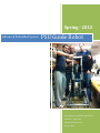
Spring -‐ 2012
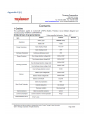
PSU Guide Robot Advanced Embedded System Omar Mohsin, Ali Alnasser and Ibrahim Almulhim ʹ Base team Portland State University Spring -‐ 2012 Table of Contents I. Introduction .......................................................................................................................................... 3 II. Robot Design ......................................................................................................................................... 3 III. Construction Parts ............................................................................................................................ 4 A. Aluminum Bars .................................................................................................................................. 4 B. Bolts .................................................................................................................................................. 5 D. Nuts ................................................................................................................................................... 5 E. Brackets ............................................................................................................................................. 5 F. Washers ............................................................................................................................................ 6 G. Spacer ................................................................................................................................................ 6 IV. Base Parts .......................................................................................................................................... 7 A. DC-‐motor controller .......................................................................................................................... 7 B. Encoder ............................................................................................................................................. 7 Features [2]: .......................................................................................................................................... 8 C. Gears ................................................................................................................................................. 8 D. Ultrasonic sensors ........................................................................................................................... 10 E. Batteries .......................................................................................................................................... 11 Specifications [4] ................................................................................................................................. 11 F. BMS ................................................................................................................................................. 12 G. Charger ............................................................................................................................................ 13 H. Bumpers .......................................................................................................................................... 13 V. Prices͙͙͙͙͙͙͙͙͙͙͙͙͙͙͙͙͙͙͙͙͙͙͙͙͙͙͙͙͙͙͙͙͙͙͙͙͙͙͙͙͙͙͙͙͙͙͙͙͙͙͙͙͙͙.14 VI. AppendŝdžĞƐ͙͙͙͙͙͙͙͙͙͙͙͙͙͙͙͙͙͙͙͙͙͙͙͙͙͙͙͙͙͙͙͙͙͙͙͙͙͙͙͙͙͙͙͙͙͙͙͙͙͙͘͘15 ƉƉĞŶĚŝdž͙͙͙͙͙͙͙͙͙͙͙͙͙͙͙͙͙͙͙͙͙͙͙͙͙͙͙͙͙͙͙͙͙͙͙͙͙͙͙͙͙͙͙͙͙͙͙͙.15 ƉƉĞŶĚŝdž͙͙͙͙͙͙͙͙͙͙͙͙͙͙͙͙͙͙͙͙͙͙͙͙͙͙͙͙͙͙͙͙͙͙͙͙͙͙͙͙͙͙͙͙͙͙͙͙..77 ƉƉĞŶĚŝdž͙͙͙͙͙͙͙͙͙͙͙͙͙͙͙͙͙͙͙͙͙͙͙͙͙͙͙͙͙͙͙͙͙͙͙͙͙͙͙͙͙͙͙͙͙͙͙͙..81 AppeŶĚŝdž͙͙͙͙͙͙͙͙͙͙͙͙͙͙͙͙͙͙͙͙͙͙͙͙͙͙͙͙͙͙͙͙͙͙͙͙͙͙͙͙͙͙͙͙͙͙͙͙.83 ƉƉĞŶĚŝdž͙͙͙͙͙͙͙͙͙͙͙͙͙͙͙͙͙͙͙͙͙͙͙͙͙͙͙͙͙͙͙͙͙͙͙͙͙͙͙͙͙͙͙͙͙͙͙͙..87 ƉƉĞŶĚŝdž&͙͙͙͙͙͙͙͙͙͙͙͙͙͙͙͙͙͙͙͙͙͙͙͙͙͙͙͙͙͙͙͙͙͙͙͙͙͙͙͙͙͙͙͙͙͙͙͙..89 References .................................................................................................................................................. 93 Table of figures Figure 1: PSU Guide Robot. ............................................................................................................. 4 Figure 2: Square/L shape Aluminum bars. ...................................................................................... 4 Figure 3: Socket screw bolts. .......................................................................................................... 5 Figure 4: Nylon nut.......................................................................................................................... 5 Figure 5: Brackets ............................................................................................................................ 6 Figure 6: Flat washer. ...................................................................................................................... 6 Figure 7: Aluminum spacer: ............................................................................................................ 6 Figure 8: RoboClaw 2x15A. ............................................................................................................. 7 Figure 9: Encoder. ........................................................................................................................... 8 Figure 10: gears to attach the encoder to the gear shaft. .............................................................. 9 Figure 11: Sensores distribution on the robot. ............................................................................ 10 Figure 12: LV‑MaxSonar‑EZ0. ...................................................................................................... 10 Figure 13: LiFeMnPO4/60AH Battery pack. ................................................................................. 11 Figure 14: BMS. ............................................................................................................................. 12 Figure 15: Charger. ........................................................................................................................ 13 Figure 16: Bumpers. ...................................................................................................................... 14 ǣ
I.
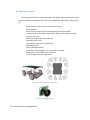
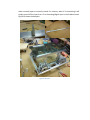
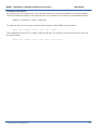
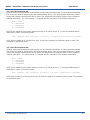
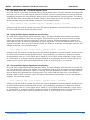
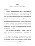
Introduction This is the second term of working on PSU_GUIDE robot. In the winter term we finished the lower part of the base. The lower part was including the Aluminum structure, Mecanum wheels, Dc-‐motors, P60 gears and an Arduino mega as a simple microcontroller for demo purposes. This term, we started working on the upper part of the base which is including the Aluminum structure, DC-‐motor controller, batteries, battery charger, Encoders, Ultrasonic sensors and Bumpers. Then, after finishing working on the upper part we finished the whole base. The body (legs, waist and the upper part that holding the arms and the head) is integrated to the base. That means the robot is ready to mount the head and arms to it. For demonstration, we will use Arduino Mega to get the input from the sonars and the bumpers then drive the base and waist. We are going to write a simple code to show that everything is working properly. II.
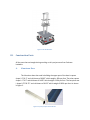
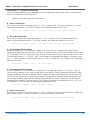
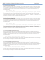
Robot Design According to our design in the google SketchUp in figure 1, the base consists of all parts mentioned in the introduction. There is a little different between the real robot and the designed one. The stepper motor part is not yet in the real robot which add one more degree of freedom that allow the robot to rotate around the z-‐axis. Figure 1: PSU Guide Robot. III.
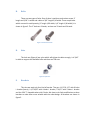
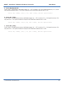
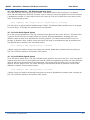
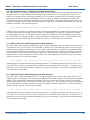
Construction Parts All the parts that we bought during working on this project were from Parkrose hardware A. Aluminum Bars The Aluminum bars that used in building the upper part of the base is square shape ϭ͘ϱ͟yϭ͘ϱ͟ĂŶĚĂƚŚŝĐŬŶĞƐƐŽĨϬ͘Ϭϲϱ͟ which weighs .45lb per foot. The other square shape is ͘ϱ͟y͘ϱ͟ĂŶĚƚŚŝĐŬŶĞƐƐŽĨϬ͘Ϭϲϱ͟ǁŚŝĐŚǁĞŝŐŚƐϬ͘ϭϯůďƉĞƌĨŽŽƚ. The last piece was L shape Ϭ͘ϳϱ͟yϬ͘ϳϱ͟ĂŶĚĂƚŚŝĐŬŶĞƐƐŽĨϬ͘ϭϮϱ͟ǁŚŝĐŚǁĞŝŐŚƐϬ͘ϮϬϱůďƉĞƌĨŽŽƚ͘ As shown in figure 2. Figure 2: Square/L shape Aluminum bars. B. Bolts There are two types of bolts. One of them is stainless steel socket screws 2͟
length ĂŶĚϯͬϭϲ͟ŝŶǁŝĚƚŚ and a bolts of 3/4͟ůĞŶŐƚŚϯͬϭϲǁŝĚƚŚ͘dŚĞƌĞĐŽƵƉůĞďŽůƚƐ
ǁŚŝĐŚĂƌĞƵƐĞĚŝŶƐŵĂůůƋƵĂŶƚŝƚLJ;ϭ͟ůĞŶŐƚŚϭͬϭϲǁŝĚƚŚ͕ϭͬϰ͟ůĞŶŐƚŚϭͬϭϲǁŝĚƚŚͿ͘ It is shown in figure 3. dŚĞϮ͟ďŽůƚƐĂƌĞϮϰƚĞĞƚŚ͕ĂƐƚŚĞƌĞĂƌĞϯϮƚĞĞƚŚĂŶd 24 teeth. Figure 3: Socket screw bolts. D. Nuts The lock nuts (figure 4ͿĂƌĞŶLJůŽŶǁŚŝĐŚǁŝůůƚŝŐŚƚĞŶƚŚĞďŽůƚƐƐƚƌŽŶŐůLJ͘/ƚŝƐϯͬϭϲ͟
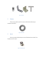
in width to support the available bolts and there are 100 nuts. Figure 4: Nylon nut. E. Brackets This time we used only four kind of bracket. They are 1-‐ϭͬϮ͟yϭ-‐ϭͬϮ͟ with 6-‐holes L bracket (brace), 1-‐1/2"X5/8" with 4-‐holes L bracket, 1"X1/2" with 2-‐holes L bracket and the 4"X4" T-‐shaped bracket with 5-‐holes. We have to do little modification to these brackets to make them more suitable with the robot design. All brackets are shown in figure 5. Figure 5: Brackets F. Washers There are many washers used in this robot to hold the bolts while they are attached to the brackets. Figure 6: Flat washer. G. Spacer Spacers are used to build the bumpers as we will talk about them in detail in the bumpers part of this report. Figure 7: Aluminum spacer: IV.
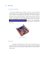
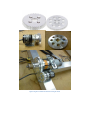
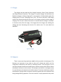
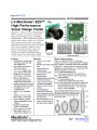
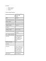
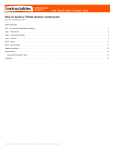
Base Parts A. DC-‐motor controller ĂƐŝĐ DŝĐƌŽ͛Ɛ ZŽďŽůĂǁ ŵŽƚŽƌ ĐŽŶƚƌŽůůĞƌ ĐĂŶ ĐŽŶƚƌŽů Ă ƉĂŝƌ ŽĨ ďƌƵƐŚĞĚ motors using serial, RC, or analog inputs. Integrated dual quadrature decoders make it easy to create a closed-‐loop speed control system. This version can supply a continuous 15 A per channel (30 A peak) [1]. Figure 8 shows a picture of this micro controller. In this robot, two of these motor controllers are used to control four DC motors. See appendix A for more information about these motor controller. http://www.pololu.com/catalog/product/1496 support all the documentations required to work in this motor controller as well as the libraries or codes related to that purpose. Figure 8: RoboClaw 2x15A. B. Encoder This encoder sends a 200 pulse per rotation. Using this encoder allows us to know the direction and the speed which allows adding a closed loop feedback controller. The encoder is shown in figure 9. Appendix B has more information about these encoders. Figure 9: Encoder. Features [2]: -‐
-‐
-‐
-‐
-‐
-‐
-‐
Resolution: 200 Pulse/Rotation Input Voltage: 5 -‐ 12VDC Maximum Rotating Speed: 5000rpm Allowable Radial Load: 5N Allowable Axial Load: 3N Cable Length: 50cm Shaft Diameter: 4mm C. Gears A Tetrix gears are used in this design. Tetrix gears are expensive as they cost $ 17-‐19. I found another source of gears which are cheaper. http://www.servocity.com/index.html this website is a good resource to find motor ĂĐĐĞƐƐŽƌŝĞƐůŝŬĞŐĞĂƌƐ͕ŚƵďƐĂŶĚďĞĂƌŝŶŐ͙ƚĐ͘In order to use these gears, the bore ŽĨƚŚĞϯ͟ ĚŝĂŵĞƚĞƌŚĂĚƚŽďĞĐŽŵĞϬ͘ϱ͕͟ƐŽǁĞŵĂĚĞƚŚĞŵďŝŐŐĞƌďLJƵƐŝŶŐĂϬ͘ϱ͟
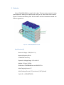
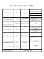
drill bit. After that we used one of the holes that surrounding the bore with the mechanical key. Using the mechanical key is to attach the gear to the bane bot gear shaft. Figure 10 shown the gears and how they are attached to the encoder as well as the gear shaft. Figure 10: gears to attach the encoder to the gear shaft. D. Ultrasonic sensors In our design a 12 ultrasonic sensors are used in this design. Figure 11 shows how these ultrasonic sensors are attached to this robot. This LV‑MaxSonar‑EZ0 (shown in figure 12) is [3]: -‐
-‐
-‐
-‐
-‐
-‐
-‐
-‐
-‐
-‐
-‐
-‐
-‐
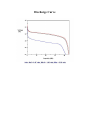
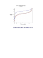
42kHz Ultrasonic sensor measures distance to objects RoHS Compliant Read from all 3 sensor outputs: Analog Voltage, Serial, Pulse Width Virtually no sensor dead zone, objects closer than 6 inches range as 6 inches Resolution of 1 inch Maximum Range of 254 inches (645 cm) Operates from 2.5-‐5.5V Low 2.0mA average current requirement 20Hz reading rate Small, lightweight module Designed for easy integration into your project or product Widest beam of the LV-‐MaxSonar-‐EZ sensors Great for people detection applications Figure 11: Sensores distribution on the robot. Figure 12: LV‑MaxSonar‑EZ0. For more information see appendix C. E. Batteries A four LiFeMnPO4/60AH are used in this robot. There are many reasons of using these batteries. Reading the specifications will give an idea about these reasons. Figure 13 shows the battery pack. All the charts and the instruction manual are found in appendix D. Figure 13: LiFeMnPO4/60AH Battery pack. Specifications [4] -‐ Nominal Voltage: 12.8V (4X 3.2 V) -‐ Nominal Capacity: 60 Ah -‐ LiFeMnPO4 chemistry -‐ Operation Voltage Range: 11.2 to 14.4V -‐ Weight: 9.2 kg or 20.3 lbs -‐ Dimension: 125X280X180 mm or 4.9X11X7.1 in -‐ Max Charging Current: 3C -‐ Max Discharge Current: 3C (continuous) / 10C (pulsed) -‐ Cycle Life : >1500 (80%DOD) -‐ Operating Temperature: -‐20 to 65 C or -‐4 to 149 F -‐ Self Discharge Rate: <3% monthly F. BMS Using battery management system is important because we are using a battery pack of 4 cells. The cells are exposed to different temperature as they worked. This difference in temperature as well as the differences in the chemical component as they are not perfect will make the voltage different from cell to cell by time. Using the BMS will protect the cells from overcharge/overdischarge, over current drown as well as keep cells having the same voltage. In appendix E, the BMS specification and user manual are found. Figure 14: BMS. G. Charger The charger that we used has Over Voltage Protection, Short Circuit Protection and Output Reverse Protection. This charger is a special charger for the lithium ion batteries (charger is shown in figure 15). It can support a 10 Amp which means the charging time is 6 hours. (Charging Time= (1.41 * Ah rate of the pack) / 10A charge current) this formula shows that the time is a bit longer as there are two stages of charging. The first one is when the current is constant and the voltage is increased. In the other hand, after this stage, is the stage when the charger start holding the voltage and start decreasing the current till it reaches zero. For more detail see appendix F. Figure 15: Charger. H. Bumpers There is one more thing have been added in this term which is the bumpers. The ďƵŵƉĞƌƐ ĂƌĞ ŝŵƉŽƌƚĂŶƚ ƚŽ ŽƵƌ ƌŽďŽƚ ĂƐ ƚŚĞƌĞ Ɛƚŝůů Ă ĚĞĂĚ njŽŶĞ ǁŚŝĐŚ ĐĂŶ͛ƚ ďĞ
recognized as obstacle by the Kinect or ultrasonic sensors. The main goal is to not use these bumpers because we should have an efficient system which able to detect the obstacle and not to crash on them. The bumpers are used for an emergency stop in a case there are no inputs from the other sensors. Tow micro-‐switches are used in each bumper. Springs as well as spacers are used to protect the micro-‐switches from being damaged during operation. Each micro-‐switch is simply operated as they work either normally open or normally closed. For instance, when it hit something it will simply turned off the input from +5 to the analog/digital input in the Arduino board. Figure 16 shows the bumpers. Figure 16: Bumpers. V.
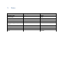
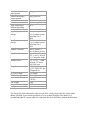
Prices Item Hardware stuffs Plastic shield DC-‐motor controller Encoder Micro switch Battery Management system board Gears Batter pack of 4 cells Aluminum Bars Total Quantity -‐-‐-‐-‐-‐ 2 2 4 10 1 Price $ 201.26 34.32 179.9 169.95 20.92 38.41 2 1 -‐-‐-‐-‐ 16.43 410.26 91.47 1,162.92 !
!""#$%&'((!()*+(
!
!
!
B0097 - RoboClaw 2 Channel 15A Motor Controller
Data Sheet
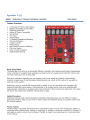
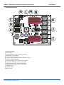
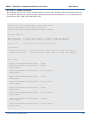
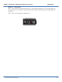
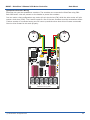
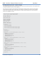
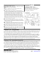
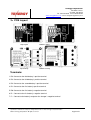
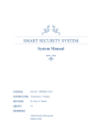
Hardware Overview:
H L M N
Status 2
M1A
Status 1
M1B
+
B
A
B-
1 2 3 4 5 6 7 8 9 10
M2B
5V
B
CTS
G
M2A
2V
ON
SW1
S1 S2 S3
F
A
B+
2 1
D
E
Basicmicro.com
LB+ LB-
C
MB
Error
LB
K
J
I
Robo Claw RevC
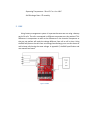
A: Microcontroller
B: DIP Switch
C: Logic Battery 3.5mm Screw Terminals
D: Encoder Input Header
E: Input Control Headers
F: VCC on Input Control Header Disable Jumper
G: Logic Voltage Regulator
H: Logic Voltage Source Selection Header
I: DC Motor Channel 2 Screw Terminals
J: Main Battery Input Screw Terminals
K: DC Motor Channel 1 Screw Terminals
L: Status LED 1
M: Status LED 2
N: Error LED
(c) 2010 BasicMicro. All Rights Reserved.
3
B0097 - RoboClaw 2 Channel 15A Motor Controller
Data Sheet
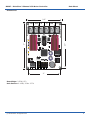
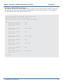
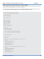
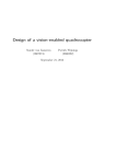
Dimensions:
2.3”
Robo Claw RevC
B-
B+
M1B
M1A
Basicmicro.com
Status 2
2.7”
1 2 3 4 5 6 7 8 9 10
CTS
ON
M2B
Error
3”
M2A
SW1
Status 1
5V
+
LB+ LB-
2V
B
A
2 1
S1 S2 S3
2”
Board Edge: 2.3”W X 3”L
Hole Pattern: 0.125D, 2”W x 2.7”H
(c) 2010 BasicMicro. All Rights Reserved.
4
B0097 - RoboClaw 2 Channel 15A Motor Controller
Data Sheet
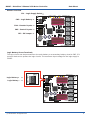
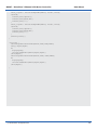
Header Overview
<-
JP1 - Logic Supply Select -
Status 2
Status 1
M1A
Error
S1 S2 S3
CTS
1 2 3 4 5 6 7 8 9 10
2V
5V
M2A
M2B
JP3 - 5V Jumper ->
ON
B-
2 1
CN5 - Control Inputs ->
SW1
CN4 - Encoder Inputs ->
B+
+
B
A
M1B
LB+ LB-
CN3 - Logic Battery ->
Basicmicro.com
Robo Claw RevC
Logic Battery Screw Terminals
The logic circuits can be powered from the main battery or a secondary battery wired to CN3. JP1
controls what source powers the logic circuits. The maximum input voltage for the logic supply is
30VDC.
Status 2
CN3
Status 1
M1A
Error
M1B
+
B
A
CTS
1 2 3 4 5 6 7 8 9 10
5V
M2A
M2B
2V
SW1
S1 S2 S3
B+
2 1
ON
B-
Logic Battery - ->
Basicmicro.com
LB+ LB-
->
|LB+|LB-|
Logic Battery +
Robo Claw RevC
(c) 2010 BasicMicro. All Rights Reserved.
5
B0097 - RoboClaw 2 Channel 15A Motor Controller
Data Sheet
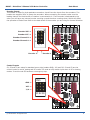
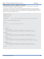
Encoder Inputs
This header is setup for dual quadrature encoders. A and B are the inputs from the encoders. The
header also supplies 5VDC to power the encoders. When connecting the encoder make sure the
leading channel for the direction of rotation is connected to A. If one encoder is backwards to the
other you will have one internal counter counting up and the other counting down. Which will affect
the operation of Robo Claw. Refer to the data sheet of the encoder you are using for channel direction.
M1A
CTS
1 2 3 4 5 6 7 8 9 10
ON
<-
-
- Encoder 1
5V
+
B
A
2V
<-
Encoder 2 -
Status 1
2|1
Robo Claw RevC
M1B
Basicmicro.com
B+
A
B-
Encoder Channel A ->
Status 2
B
SW1
Error
Encoder Channel B ->
M2B
+
M2A
Encoder VCC ->
CN4
Encoder VSS ->
2 1
LB+ LB-
S1 S2 S3
Control Inputs
S1, S2 and S3 are setup for standard servo style headers GND, +5V and I/O. S1 and S2 are the
control inputs for serial, analog and RC modes. S3 used as a flip switch input when in RC or Analog
modes. In serial mode S3 becomes a emergency stop.
M1B
M1A
CTS
Status 2
Status 1
S1 S2 S3
1 2 3 4 5 6 7 8 9 10
ON
I/O ->
Robo Claw RevC
B+
Basicmicro.com
BSW1
Error
VCC ->
M2B
GND ->
M2A
CN5
-
2V
5V
+
B
A
LB+ LB-
(c) 2010 BasicMicro. All Rights Reserved.
2 1
S1 S2 S3
6
B0097 - RoboClaw 2 Channel 15A Motor Controller
Data Sheet
BEC Jumper
VCC on control input headers S1,S2 and S3 can be turned off, on or 2V by the jumper near S3 on
CN5. Removing the BEC jumper disables VCC on S1, S2 and S3 headers. In some systems the RC
receiver may have its own supply and will conflict with the RoboClaw logic supply.
B+
M1B
M1A
Status 2
2V
CTS
1 2 3 4 5 6 7 8 9 10
Error
ON
5V
B-
Robo Claw RevC
M2B
Basicmicro.com
M2A
SW1
Status 1
5V
+
2V
B
A
2 1
LB+ LB-
S1 S2 S3
Emergency Stop
In serial mode S3 becomes the emergency stop. S3 is active low. It is internally pulled up so it will
not accidentally trip.
Robo Claw RevC
B-
B+
M1B
M1A
CTS
1 2 3 4 5 6 7 8 9 10
Error
ON
M2B
Basicmicro.com
M2A
SW1
GND
VCC
Status 2
I/O
Status 1
5V
+
LB+ LB-
2V
B
A
2 1
S1 S2 S3
(c) 2010 BasicMicro. All Rights Reserved.
7
B0097 - RoboClaw 2 Channel 15A Motor Controller
Data Sheet
Logic Supply Select
The RoboClaw logic requires 5VDC which is provided from the on board regulator. The regulator
source input is set with the logic supply jumper. Set to LB for a separate logic battery or MB for the
main battery as the source.
Robo Claw RevC
B+
M1B
M1A
Basicmicro.com
B1 2 3 4 5 6 7 8 9 10
CTS
ON
Status 2
MB
M2B
Error
MB
Status 1
LB
M2A
SW1
5V
LB
+
LB+ LB-
(c) 2010 BasicMicro. All Rights Reserved.
2V
B
A
2 1
S1 S2 S3
8
B0097 - RoboClaw 2 Channel 15A Motor Controller
Data Sheet
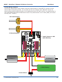
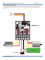
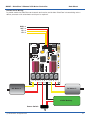
Main Battery Screw Terminals
The main battery connections are marked with a B- and B+ on the main screw terminal. B+ is the
positive side of the battery typically marked with a red wire. The B- is the negative side of the battery
and typically marked with a black wire. When connecting the main battery its a good practice to use a
switch to turn the main power on and off. When placing a switch in between the RoboClaw and main
battery you must use a switch with the proper current rating. Since the RoboClaw can draw up to
30Amps peak you should use a switch rated for at least 40Amps. The main battery can be 6V to 30V
DC.
B+
M1B
M1A
Power Switch
M2A
M2B
B-
12VDC Battery
DC Motor 1
M2A
M2B
B-
B+
M1B
M1A
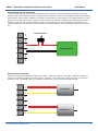
Motor Screw Terminals
The motor screw terminals are marked with M1A / M1B for channel 1 and M2A / M2B for channel 2.
There is no specific polarities for the motors. However if you want both motors turning in the same
direction on a 4 wheeled robot you need to reverse one of the motors as shown below:
(c) 2010 BasicMicro. All Rights Reserved.
DC Motor 2
DC Motor 1
9
B0097 - RoboClaw 2 Channel 15A Motor Controller
Data Sheet
Status and Error LEDs
The RoboClaw has 3 main LEDs. 2 Status LEDs and 1 Error LED. When Robo Claw is first powered up
all 3 LED should blink several times briefly to indicate all 3 LEDs are functional. The status LEDs will
indicate a status based on what mode RoboClaw is set to.
Robo Claw RevC
M2A
M2B
5V
S1 S2 S3
1 2 3 4 5 6 7 8 9 10
ON
SW1
2V
BCTS
M1A
LB+ LB-
+
B
A
M1B
2 1
B+
<-----
MB
<--------
Status 1
LB
Status 2
<--
Error
Basicmicro.com
-- Status LED 1
-------- Status LED 2
---------------- Error LED
Analog Mode
Status LED 1 = On continuous.
Status LED 2 = On when motor(s) active.
RC Mode
Status LED 1 = On continuous, blink when pulse received.
Status LED 2 = On when motor(s) active.
Serial Modes
Status LED 1 = On continuous, blink on serial receive.
Status LED 2 = On when motor(s) active.
Errors
Over Current
Over Heat
Main Batt Low
Main Batt High
Logic Batt Low
Logic Batt High
(c) 2010 BasicMicro. All Rights Reserved.
=
=
=
=
=
=
Error
Error
Error
Error
Error
Error
LED
LED
LED
LED
LED
LED
on solid. Status 1 or 2 indicates which motor.
blinking once with a long pause.
blinking twice with a long pause.
on fast flicker until condition is cleared.
blinking three times with a long pause.
blinking four times with a long pause.
10
B0097 - RoboClaw 2 Channel 15A Motor Controller
Data Sheet
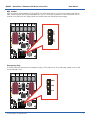
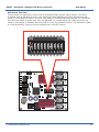
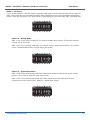
DIP Switch Overview
The dip switch on RoboClaw is used to set its operating modes and the many options. The switch
is marked with an ON label at its top. The switches are also labeled from left to right starting with
switch 1 and ending with switch 10. When a dip switch is moved toward the label ON it is considered
ON. When the switch is facing away from the ON label it is considered off. Be careful to ensure the
switch is not floating in between and is firmly OFF or ON. See illustration below. The red switch (SW1)
is in the ON position. The grey colored switches are in the OFF position.
ON
CTS
1 2 3 4 5 6 7 8 9 10
Status 2
Basicmicro.com
-
+
B
A
M1B
LB+ LB-
M1A
Status 1
MB
Error
LB
CTS
5V
M2A
M2B
2V
B-
1 2 3 4 5 6 7 8 9 10
SW1
S1 S2 S3
B+
2 1
ON
Robo Claw RevC
(c) 2010 BasicMicro. All Rights Reserved.
11
B0097 - RoboClaw 2 Channel 15A Motor Controller
Data Sheet
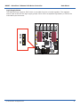
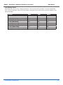
Low Voltage Cutoff
RoboClaw has a built in low voltage protection. This has two main purposed. To protect RoboClaw
from running erratically when the main battery level gets to low and protect a Lithium battery from
being damaged.
Voltage
SW8
SW9
SW10
Not Monitored
OFF
OFF
OFF
Lead Acid - Auto
ON
OFF
OFF
2- Cell (6V Cutoff)
OFF
ON
OFF
3- Cell (9V Cutoff)
ON
ON
OFF
4- Cell (12V Cutoff)
OFF
OFF
ON
5- Cell (15V Cutoff)
ON
OFF
ON
6- Cell (18V Cutoff)
OFF
ON
ON
7- Cell (21V Cutoff)
ON
ON
ON
(c) 2010 BasicMicro. All Rights Reserved.
12
B0097 - RoboClaw 2 Channel 15A Motor Controller
Data Sheet
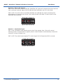
RoboClaw Modes
There are 4 modes. Each with a specific way to control RoboClaw. The following list explain each mode
and the ideal application.
Mode 1 - RC Input
With RC input mode RoboClaw can be controlled from any hobby RC radio system. RC input mode also
allows low powered microcontroller such as a Basic Stamp or Nano to control RoboClaw. RoboClaw
expects servo pulse inputs to control the direction and speed. Very similar to how a regular servo is
controlled. RC mode can not use encoders.
Mode 2 - Analog
Analog mode uses an analog signal from 0V to 5V to control the speed and direction of each motor.
RoboClaw can be controlled using a potentiometer or filtered PWM from a microcontroller. Analog mode
is ideal for interfacing RoboClaw joystick positioning systems or other non microcontroller interfacing
hardware. Analog mode can not use encoders.
Mode 3 - Simple Serial
In simple serial mode RoboClaw expects TTL level RS-232 serial data to control direction and speed of
each motor. Simple serial is typically used to control RoboClaw from a microcontroller or PC. If using a
PC a MAX232 type circuit must be used since RoboClaw only works with TTL level input. Simple serial
includes a slave select mode which allows multiple RoboClaws to be controlled from a signal RS-232
port (PC or microcontroller). Simple serial is a one way format, RoboClaw only receives data.
Mode 4 - Packet Serial
In packet serial mode RoboClaw expects TTL level RS-232 serial data to control direction and speed of
each motor. Packet serial is typically used to control RoboClaw from a microcontroller or PC. If using
a PC a MAX232 type circuit must be used since RoboClaw only works with TTL level input. In packet
serial mode each RoboClaw is assigned an address using the dip switches. There are 8 addresses
available. This means up to 8 RoboClaws can be on the same serial port. When using the quadrature
decoding feature of RoboClaw packet serial is required since it is a two way communications format.
This allows RoboClaw to transmit information about the encoders position and speed.
(c) 2010 BasicMicro. All Rights Reserved.
13
B0097 - RoboClaw 2 Channel 15A Motor Controller
Data Sheet
RC Input
(c) 2010 BasicMicro. All Rights Reserved.
14
B0097 - RoboClaw 2 Channel 15A Motor Controller
Data Sheet
Mode 1 - RC Input
For RC mode set SW1 = ON. RC mode is typically used when controlling RoboClaw from a hobby RC
radio. This mode can also be used to simplify driving RoboClaw from a microcontroller using servo
pulses. There are 4 options in RC Input mode. These options are set with SW4, SW5, SW6 and SW7.
ON
CTS
1 2 3 4 5 6 7 8 9 10
Switch 4 - Mixing Mode
SW4 = ON: Turns mixing mode ON. S1 controls forward and reverse. S2 controls steering.
Control will be like a car.
SW4 = OFF: Turns mixing mode OFF. S1 controls motor 1 speed and direction. S2 controls
motor 2 speed and direction. Control will be like a tank.
ON
CTS
1 2 3 4 5 6 7 8 9 10
Switch 5 - Exponential Mode
SW5 = ON: Turns exponential mode ON. Exponential response softens the center control
position. This mode is ideal with tank style robots.
SW5 = OFF: Turns exponential mode OFF. Motor response will be linear and directly
proportional to the control input. Ideal for 4 wheel style robots.
ON
CTS
1 2 3 4 5 6 7 8 9 10
(c) 2010 BasicMicro. All Rights Reserved.
15
B0097 - RoboClaw 2 Channel 15A Motor Controller
Data Sheet
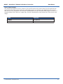
Switch 6 - MCU or RC Control
SW6 = ON: Turns MCU control mode ON. RoboClaw will continue to execute last pulse received
until new pulse received. Signal lost fail safe and auto calibration are off in this mode.
SW6 = OFF: Turns RC control mode ON. RoboClaw will calibrate the center and end points
automatically to maximize stick throw. This mode includes a fail safe. If control input is lost,
RoboClaw will shut down.
ON
CTS
1 2 3 4 5 6 7 8 9 10
Switch 7 - Flip Switch Input
SW7 = ON: Flip switch input requires servo pulse. Pulse greater than 1.5ms will reverse
steering control. The flip switch is typically used in robot combats to automatically reverse the
controls if a robot is flipped over.
SW7 = OFF: Flip switch input expects TTL control signal. 0V for flipped and 5V for normal.
ON
CTS
1 2 3 4 5 6 7 8 9 10
(c) 2010 BasicMicro. All Rights Reserved.
16
B0097 - RoboClaw 2 Channel 15A Motor Controller
Data Sheet
Servo Pulse Ranges
The RoboClaw expects RC servo pulses on S1 and S2 to drive the motors when the dip switches are
set for RC mode. The center points are calibrated at start up. 1000us is the default for full reverse
and 2000us is the default for full forward. The RoboClaw will auto calibrate these ranges on the fly. If
a pulse smaller than 1000us or larger than 2000us is detected the new pulses will be set as the new
range.
Pulse
Function
1000us
Full Reverse
2000us
Full Forward
(c) 2010 BasicMicro. All Rights Reserved.
17
B0097 - RoboClaw 2 Channel 15A Motor Controller
Data Sheet
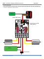
RC Wiring Example
Connect the RoboClaw as shown below. Set switches SW1 and SW4 to ON. Make sure you center the
control sticks and turn the radio on first, then the receiver, then RoboClaw. It will take RoboClaw about
1 second to calibrate the neutral position.
<-
Remove BEC Jumper
AR6000
BAT
THR
AILE
ELE
RUD
GER
AUX
!"#$%&'(
~
+
-
Battery
LB+ LB-
2 1
S1 S2 S3
5V
LB
+
B
A
2V
Status 2
Status 1
MB
<- Install Jumper on MB
(Main Battery)
Error
ON
Basicmicro.com
CTS
1 2 3 4 5 6 7 8 9 10
Robo Claw RevC
SW1
M2A
M2B
B-
B+
M1B
M1A
DC Motor 1
DC Motor 2
Battery
Power Switch
(c) 2010 BasicMicro. All Rights Reserved.
18
B0097 - RoboClaw 2 Channel 15A Motor Controller
Data Sheet
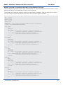
RC Control - Arduino Example
The example will drive a 2 motor 4 wheel robot in reverse, stop, forward, left turn and then right turn.
The program was written and tested with a Arduino Uno and P5 connected to S1, P6 connected to S2.
Set switches SW1, SW4, SW5 and SW6 to ON.
//Basic Micro Robo Claw RC Mode. Control Robo Claw
//with servo pulses from a microcontroller.
//Switch settings: SW1=ON, SW4=ON, SW5=ON and SW6=ON
#include <Servo.h>
Servo myservo1;
Servo myservo2;
int pos = 0;
// create servo object to control a Roboclaw channel
// create servo object to control a Roboclaw channel
// variable to store the servo position
void setup()
{
myservo1.attach(5);
myservo2.attach(6);
}
// attaches the RC signal on pin 5 to the servo object
// attaches the RC signal on pin 6 to the servo object
void loop()
{
myservo1.writeMicroseconds(1500);
myservo2.writeMicroseconds(1500);
delay(2000);
//Stop
//Stop
myservo1.writeMicroseconds(1250);
delay(1000);
//full forward
myservo1.writeMicroseconds(1500);
delay(2000);
//stop
myservo1.writeMicroseconds(1750);
delay(1000);
//full reverse
myservo1.writeMicroseconds(1500);
delay(2000);
//Stop
myservo2.writeMicroseconds(1250);
delay(1000);
//full forward
myservo2.writeMicroseconds(1500);
delay(2000);
//Stop
myservo2.writeMicroseconds(1750);
delay(1000);
//full reverse
}
(c) 2010 BasicMicro. All Rights Reserved.
19
B0097 - RoboClaw 2 Channel 15A Motor Controller
Data Sheet
RC Control - BasicATOM Pro Example
The example will drive a 2 motor 4 wheel robot in reverse, stop, forward, left turn and then right turn.
The program was written and tested with a BasicATOM Pro and P0 connected to S1, P1 connected to
S2. Set switches SW1, SW4, SW5 and SW6 to ON.
;Basic Micro Robo Claw RC Mode. Control Robo Claw
;with servo pulses from a microcontroller.
;Switch settings: SW1=ON, SW4=ON, SW5=ON and SW6=ON
Main
pulsout P15,(1500*2)
pulsout P14,(1500*2)
pause 2000
; stop
; stop
pulsout P15,(500*2)
pause 1000
; full backward
pulsout P15,(1500*2)
pause 2000
; stop
pulsout P15,(2500*2)
pause 1000
; full forward
pulsout P15,(1500*2)
pause 2000
; stop
pulsout P14,(500*2)
pause 1000
; left turn
pulsout P14,(1500*2)
pause 2000
; stop
pulsout P14,(2500*2)
pause 1000
; right turn
goto main
(c) 2010 BasicMicro. All Rights Reserved.
20
B0097 - RoboClaw 2 Channel 15A Motor Controller
Data Sheet
Analog Input
(c) 2010 BasicMicro. All Rights Reserved.
21
B0097 - RoboClaw 2 Channel 15A Motor Controller
Data Sheet
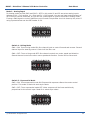
Mode 2 - Analog Input
For Analog mode set SW1,SW2 and SW3 = OFF. In this mode S1 and S2 are set as analog inputs.
Voltages of 0V = Full reverse, 1V = Stop and 2V = Full forward. You can use linear potentiometers of
1K to 100K to control RoboClaw. Or you can use a PWM signal to control RoboClaw in analog mode.
If using a PWM signal to control RoboClaw you will need a simple filter circuit to clean up the pulse. If
using a potentiometer set the BEC header to 2V.
ON
CTS
1 2 3 4 5 6 7 8 9 10
Switch 4 - Mixing Mode
SW4 = ON: Turns mixing mode ON. One channel input to control forward and reverse. Second
channel input for steering control. Control will be like a car.
SW4 = OFF: Turns mixing mode OFF. One channel controls one motor speed and direction.
Second channel controls the other motor speed and direction. Control will be like a tank.
ON
CTS
1 2 3 4 5 6 7 8 9 10
Switch 5 - Exponential Mode
SW5 = ON: Turns exponential mode ON. Exponential response softens the center control
position. This mode is ideal with tank style robots.
SW5 = OFF: Turns exponential mode OFF. Motor response will be linear and directly
proportional to the control input. Ideal for 4 wheel style robots.
ON
CTS
1 2 3 4 5 6 7 8 9 10
(c) 2010 BasicMicro. All Rights Reserved.
22
B0097 - RoboClaw 2 Channel 15A Motor Controller
Data Sheet
Switch 7 - Flip Switch
SW7 = ON: Turns the flip switch input S3 on. The flip switch signal is a TTL driven signal. 0V
is active and 5V is not active. When the flip switch signal is active all inputs to RoboClaw are
reversed.
SW7 = OFF: Turns flip switch input S3 off.
ON
CTS
1 2 3 4 5 6 7 8 9 10
(c) 2010 BasicMicro. All Rights Reserved.
23
B0097 - RoboClaw 2 Channel 15A Motor Controller
Data Sheet
Analog Wiring Example
Connect the RoboClaw as shown below using two potentiometers. Install BEC 2V jumper and set
switch SW4 to ON (Mixing Mode). You can also use the wire example with SW4 OFF. Center the
potentiometers before applying power or the attached motors will start moving. S1 potentiometer in
mix mode (SW4) will control forward and reverse. S2 potentiometer in mix mode (SW4) will control
turning (LEFT / RIGHT).
10K
10K
S1 Potentiometer
LB+ LB-
2 1
S1 S2 S3
+
B
A
2V
S2 Potentiometer
5V
LB
-
Status 2
Status 1
MB
<- Install Jumper on MB
(Main Battery)
Error
ON
Basicmicro.com
CTS
1 2 3 4 5 6 7 8 9 10
Robo Claw RevC
SW1
M2A
M2B
DC Motor 1
B-
B+
M1B
M1A
DC Motor 2
12VDC Battery
Power Switch
(c) 2010 BasicMicro. All Rights Reserved.
24
B0097 - RoboClaw 2 Channel 15A Motor Controller
Data Sheet
Simple Serial
(c) 2010 BasicMicro. All Rights Reserved.
25
B0097 - RoboClaw 2 Channel 15A Motor Controller
Data Sheet
Mode 3 - Simple Serial
Simple Serial mode set SW1 = OFF, SW2 = ON and SW3 = OFF. In this mode S1 accepts TTL level byte
commands. RoboClaw is receive only and uses 8N1 format which is 8 bits, no parity bits and 1 stop
bit. If your using a microcontroller you can interface directly to RoboClaw. If your using a PC a level
shifting circuit is required (MAX232). The baud rate is set by the dip switches.
ON
CTS
1 2 3 4 5 6 7 8 9 10
Switch 1 - Slave Select
SW1 = ON: Turns slave select ON. Slave select is used when more than one RoboClaw is on
the same serial bus. When slave select is set to ON the S2 pin becomes the select pin. Set S2
high (5V) and RoboClaw will execute the next commands. Set S2 low (0V) and RoboClaws will
ignore all sent commands.
ON
CTS
1 2 3 4 5 6 7 8 9 10
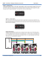
Simple Serial Slave
Setting up the RoboClaw for serial slave is straight forward. Make sure all RoboClaws share
a common signal ground (GND) shown by the black wire. P0 (Brown line) is connected to S1
of all 3 RoboClaws which is the serial in of the RoboClaw. P1, P2 and P3 are connected to S2.
Only one MCU pin is connected to each RoboClaws S2 pin. To enable RoboClaw hold S2 high
otherwise any commands sent is ignored.
1
LB+ LB-
S1 S2 S3
+
2
1
LB+ LB-
S1 S2 S3
B
A
+
Status 1
Status 2
Status 1
Status 1
S1 S2 S3
Status 2
Status 2
1
+
Error
Error
Error
2
B
A
SW1
M1A
SW1
M1B
Basicmicro.com
B+
CTS
B-
1 2 3 4 5 6 7 8 9 10
M2B
ON
Basicmicro.com
M2A
Robo Claw RevC
CTS
1 2 3 4 5 6 7 8 9 10
SW1
M1A
ON
Basicmicro.com
M1B
Robo Claw RevC
B+
MB
MB
MB
B-
LB
LB
LB
CTS
1 2 3 4 5 6 7 8 9 10
ON
(c) 2010 BasicMicro. All Rights Reserved.
M2B
2
5V
5V
5V
Robo Claw RevC
M2A
B
A
2V
2V
2V
MCU
LB+ LB-
GND
SOUT
IN1
IN2
IN3
M2A
M2B
B-
B+
M1B
M1A
26
B0097 - RoboClaw 2 Channel 15A Motor Controller
Data Sheet
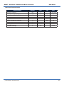
Baud Rate
RoboClaw supports 4 baud rates in serial mode. The baud rate is selected by setting switch 4 and 5.
Baud Rate
SW4
SW5
2400
OFF
OFF
9600
ON
OFF
19200
OFF
ON
38400
ON
ON
2400 Baud
ON
9600 Baud
CTS
ON
CTS
1 2 3 4 5 6 7 8 9 10
1 2 3 4 5 6 7 8 9 10
19200 Baud
38400 Baud
ON
CTS
1 2 3 4 5 6 7 8 9 10
ON
CTS
1 2 3 4 5 6 7 8 9 10
Simple Serial Command Syntax
The RoboClaw simple serial is setup to control both motors with one byte sized command character.
Since a byte can be anything from 0 to 255 the control of each motor is split. 1 to 127 controls
channel 1 and 128 to 255 controls channel 2. Command character 0 will shut down both channels. Any
characters in between will control speed, direction of each channel.
Character
Function
0
Shuts Down Channel 1 and 2
1
Channel 1 - Full Reverse
64
Channel 1 - Stop
127
Channel 1 - Full Forward
128
Channel 2 - Full Reverse
192
Channel 2 - Stop
255
Channel 2 - Full Forward
(c) 2010 BasicMicro. All Rights Reserved.
27
B0097 - RoboClaw 2 Channel 15A Motor Controller
Data Sheet
Simple Serial Wiring Example
In simple serial mode the RoboClaw can only receive serial data. Use the below wiring diagrahm with
the following code examples. Make sure you install the BEC jumper to 5V if powering the MCU from
RoboClaw.
GND ->
VCC ->
I/O ->
LB+ LB-
2 1
S1 S2 S3
A
2V
LB
+
B
5V
Status 2
Status 1
MB
<- Install Jumper on MB
(Main Battery)
Error
ON
Basicmicro.com
CTS
1 2 3 4 5 6 7 8 9 10
Robo Claw RevC
SW1
M2A
M2B
DC Motor 1
B-
B+
M1B
M1A
DC Motor 2
12VDC Battery
Power Switch ->
(c) 2010 BasicMicro. All Rights Reserved.
28
B0097 - RoboClaw 2 Channel 15A Motor Controller
Data Sheet
Simple Serial - Arduino Example
The following example will start both channels in reverse, stop, then full speed forward. The program
was written and tested with a Arduino Uno and Pin 5 connected to S1. Set switch SW2 and SW5 to ON.
ON
CTS
1 2 3 4 5 6 7 8 9 10
//Basic Micro Robo Claw Simple Serial Test
//Switch settings: SW2=ON and SW5=ON
//Make sure Arduino and Robo Claw share common GND!
#include “BMSerial.h”
BMSerial mySerial(5,6);
void setup() {
mySerial.begin(19200);
}
void loop() {
mySerial.write(1);
mySerial.write(-1);
delay(2000);
mySerial.write(127);
mySerial.write(-127);
delay(2000);
}
(c) 2010 BasicMicro. All Rights Reserved.
29
B0097 - RoboClaw 2 Channel 15A Motor Controller
Data Sheet
Simple Serial - BasicATOM Pro Example
The following example will start both channels in reverse, stop, then full speed forward. The program
was written and tested with a BasicATOM Pro and P0 connected to S1. Set switch SW2 and SW5 to ON.
ON
CTS
1 2 3 4 5 6 7 8 9 10
;Basic Micro Robo Claw Simple Serial Test
;Switch settings: SW2=ON and SW5=ON
;Make sure BAP and Robo Claw share common GND!
Main
Serout P15, i19200, [0] ;Full stop both channels
Pause 500
Serout P15, i19200, [96,224] ;Foward slowly
Pause 3000
Serout P15, i19200, [127,255] ;Foward fast
Pause 3000
Serout P15, i19200, [64,192] ;Full stop both channels
Pause 500
Serout P15, i19200, [32,160] ;Reverse slowly
Pause 3000
Serout P15, i19200, [1,128] ;Reverse fast
Pause 3000
Goto Main
(c) 2010 BasicMicro. All Rights Reserved.
30
B0097 - RoboClaw 2 Channel 15A Motor Controller
Data Sheet
Packet Serial
(c) 2010 BasicMicro. All Rights Reserved.
31
B0097 - RoboClaw 2 Channel 15A Motor Controller
Data Sheet
Mode 4 - Packet Serial
Packet serial mode set SW3 = ON and then selected address. See table below. Packet serial is used to
communicate more sophisticated instructions to RoboClaw. RoboClaw can send or receive serial data
in packet mode. The basic command structures consists of address byte, command byte, data bytes
and a checksum. The amount of data each command will send or receive can vary. In packet mode the
RoboClaw serial commands are buffered for more complex functionality.
ON
CTS
1 2 3 4 5 6 7 8 9 10
Baud Rate
Packet serial supports the same baud rate modes as simple serial and uses the same RS232 8N1
format. The following table defines the available baud rates and their respective switch settings.
Baud Rate
SW4
SW5
2400
OFF
OFF
9600
ON
OFF
19200
OFF
ON
38400
ON
ON
Address
When using packet serial each RoboClaw must be assigned a unique address. With up to 8 addresses
available you can have up to 8 RoboClaws bussed on the same RS232 port. The following table defines
the addresses and their respective switch settings.
Address
SW1
SW6
SW7
128 (0x80)
OFF
OFF
OFF
129 (0x81)
OFF
ON
OFF
130 (0x82)
OFF
OFF
ON
131 (0x83)
OFF
ON
ON
132 (0x84)
ON
OFF
OFF
133 (0x85)
ON
ON
OFF
134 (0x86)
ON
OFF
ON
135 (0x87)
ON
ON
ON
(c) 2010 BasicMicro. All Rights Reserved.
32
B0097 - RoboClaw 2 Channel 15A Motor Controller
Data Sheet
Checksum Calculation
All packet serial commands use a 7 bit checksum to prevent corrupt commands from being executed.
Since the RoboClaw expects a 7bit value the 8th bit is masked. The checksum is calculated as follows:
Address + Command + Data = Checksum
To mask the 8th bit you use can a simple math expression called AND as shown below:
Serout P15, i19200, [128, 0, 127, (255 & 0X7F)]
The hexadecimal value 0X7F is used to mask the 8th bit. You can also use a binary value of 01111111
as shown below:
Serout P15, i19200, [128, 0, 127, (255 & %01111111)]
(c) 2010 BasicMicro. All Rights Reserved.
33
B0097 - RoboClaw 2 Channel 15A Motor Controller
Data Sheet
Commands 0 - 7 Standard Commands
The following commands are the standard set of commands used with packet mode. The command
syntax is the same for commands 0 to 7:
Address, Command, ByteValue, Checksum
0 - Drive Forward M1
Drive motor 1 forward. Valid data range is 0 - 127. A value of 127 = full speed forward, 64 = about
half speed forward and 0 = full stop. Example with RoboClaw address set to 128:
Serout P15, i19200, [128, 0, 127, (255 & 0X7F)] ;M1 full speed forward
1 - Drive Backwards M1
Drive motor 1 backwards. Valid data range is 0 - 127. A value of 127 full speed backwards, 64 =
about half speed backward and 0 = full stop. Example with RoboClaw address set to 128:
Serout P15, i19200, [128, 1, 127, (256 & 0X7F)] ;M1 full speed forward
2 - Set Minimum Main Voltage
Sets main battery (B- / B+) minimum voltage level. If the battery voltages drops below the set
voltage level RoboClaw will shut down. The value is cleared at start up and must set after each power
up. The voltage is set in .2 volt increments. A value of 0 sets the minimum value allowed which is 6V.
The valid data range is 0 - 120 (6V - 30V). The formula for calculating the voltage is: (Desired Volts 6) x 5 = Value. Examples of valid values are 6V = 0, 8V = 10 and 11V = 25. Example with RoboClaw
address set to 128:
Serout P15, i19200, [128, 2, 25, (165 & 0X7F)]
3 - Set Maximum Main Voltage
Sets main battery (B- / B+) maximum voltage level. The valid data range is 0 - 154 (0V - 30V). If
you are using a battery of any type you can ignore this setting. During regenerative breaking a back
voltage is applied to charge the battery. When using an ATX type power supply if it senses anything
over 16V it will shut down. By setting the maximum voltage level, RoboClaw before exceeding it will
go into hard breaking mode until the voltage drops below the maximum value set. The formula for
calculating the voltage is: Desired Volts x 5.12 = Value. Examples of valid values are 12V = 62, 16V
= 82 and 24V = 123. Example with RoboClaw address set to 128:
Serout P15, i19200, [128, 3, 82, (213 & 0X7F)]
4 - Drive Forward M2
Drive motor 2 forward. Valid data range is 0 - 127. A value of 127 full speed forward, 64 = about half
speed forward and 0 = full stop. Example with RoboClaw address set to 128:
Serout P15, i19200, [128, 4, 127, (259 & 0X7F)] ;M2 full speed forward
(c) 2010 BasicMicro. All Rights Reserved.
34
B0097 - RoboClaw 2 Channel 15A Motor Controller
Data Sheet
5 - Drive Backwards M2
Drive motor 2 backwards. Valid data range is 0 - 127. A value of 127 full speed backwards, 64 = about
half speed backward and 0 = full stop. Example with RoboClaw address set to 128:
Serout P15, i19200, [128, 5, 127, (260 & 0X7F)] ;M2 full speed forward
6 - Drive M1 (7 Bit)
Drive motor 1 forward and reverse. Valid data range is 0 - 127. A value of 0 = full speed reverse, 64 =
stop and 127 = full speed forward. Example with RoboClaw address set to 128:
Serout P15, i19200, [128, 6, 96, (230 & 0X7F)] ;M1 half speed forward
7 - Drive M2 (7 Bit)
Drive motor 2 forward and reverse. Valid data range is 0 - 127. A value of 0 = full speed reverse, 64 =
stop and 127 = full speed forward. Example with RoboClaw address set to 128:
Serout P15, i19200, [128, 7, 32, (167 & 0X7F)] ;M2 half speed reverse
(c) 2010 BasicMicro. All Rights Reserved.
35
B0097 - RoboClaw 2 Channel 15A Motor Controller
Data Sheet
Commands 8 - 13 Mix Mode Commands
The following commands are mix mode commands and used to control speed and turn. Before a
command is executed valid drive and turn data is required. You only need to send both data packets
once. After receiving both valid drive and turn data RoboClaw will begin to operate. At this point you
only need to update turn or drive data.
8 - Drive Forward
Drive forward in mix mode. Valid data range is 0 - 127. A value of 0 = full stop and 127 = full forward.
Example with RoboClaw address set to 128:
Serout P15, i19200, [128, 8, 127, (263 & 0x7F)] ;full speed forward
9 - Drive Backwards
Drive backwards in mix mode. Valid data range is 0 - 127. A value of 0 = full stop and 127 = full
reverse. Example with RoboClaw address set to 128:
Serout P15, i19200, [128, 9, 127, (264 & 0x7F)] ;full speed reverse
10 - Turn right
Turn right in mix mode. Valid data range is 0 - 127. A value of 0 = stop turn and 127 = full speed turn.
Example with RoboClaw address set to 128:
Serout P15, i19200, [128, 10, 127, (265 & 0x7F1)] ;full speed right turn
11 - Turn left
Turn left in mix mode. Valid data range is 0 - 127. A value of 0 = stop turn and 127 = full speed turn.
Example with RoboClaw address set to 128:
Serout P15, i19200, [128, 11, 127, (266 & 0x7F)] ;full speed left turn
12 - Drive Forward or Backward (7 Bit)
Drive forward or backwards. Valid data range is 0 - 127. A value of 0 = full backward, 64 = stop and
127 = full forward. Example with RoboClaw address set to 128:
Serout P15, i19200, [128, 12, 96, (236 & 0x7F)] ;medium speed forward
13 - Turn Left or Right (7 Bit)
Turn left or right. Valid data range is 0 - 127. A value of 0 = full left, 0 = stop turn and 127 = full
right. Example with RoboClaw address set to 128:
Serout P15, i19200, [128, 13, 0, (141 & 0x7F)] ;full speed turn left
(c) 2010 BasicMicro. All Rights Reserved.
36
B0097 - RoboClaw 2 Channel 15A Motor Controller
Data Sheet
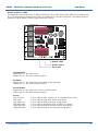
Packet Serial Wiring
In packet mode the RoboClaw can transmit and receive serial data. RoboClaw is transmitting return
data a processor with a hardware serial port is required.
->
->
->
->
S1 S2 S3 +5V
2|1
R2
R29
Robo Claw
ON
Status1
C9
R9
1 2 3 4 5 6 7 8 9 10
CTS
R1
Status2
Q14
C3
C4
R3
R7
R4 R6
U2
R30
R16 VD2 R15
R17
R25
CN4
C20
U4
C19
R13
R2
C1
JP3
Y1
C2 C5
C14
C21
R18
R28
C22
JP2
CN5
JP1
+
Power Sel
Error R5
Reset
B
C13
CN3
A
R32
VD3
GND
VCC
S1
S2
SW1
M1A
M1B
B+
B-
M2B
M2A
Basicmicro.com (c) 2009
DC Motor 1
DC Motor 2
12VDC Battery
Power Switch
(c) 2010 BasicMicro. All Rights Reserved.
37
B0097 - RoboClaw 2 Channel 15A Motor Controller
Data Sheet
Packet Serial - Arduino Example
The example will start the motor channels independently. Then start turns with mix mode commands.
The program was written and tested with a Arduno Uno and P5 connected to S1. Set switch SW3 and
SW5 to ON.
//Basic Micro Robo Claw Packet Serial Test Commands 0 to 13.
//Switch settings: SW3=ON and SW5=ON.
#include “BMSerial.h”
#include “RoboClaw.h”
#define address 0x80
RoboClaw roboclaw(5,6);
void setup() {
roboclaw.begin(19200);
}
void loop() {
roboclaw.ForwardM1(address,64); //Cmd 0
roboclaw.BackwardM2(address,64); //Cmd 5
delay(2000);
roboclaw.BackwardM1(address,64); //Cmd 1
roboclaw.ForwardM2(address,64); //Cmd 6
delay(2000);
roboclaw.ForwardBackwardM1(address,96);
roboclaw.ForwardBackwardM2(address,32);
delay(2000);
roboclaw.ForwardBackwardM1(address,32);
roboclaw.ForwardBackwardM2(address,96);
delay(2000);
//Cmd 6
//Cmd 7
//Cmd 6
//Cmd 7
//stop motors
roboclaw.ForwardBackwardM1(address,0);
roboclaw.ForwardBackwardM2(address,0);
delay(10000);
roboclaw.ForwardMixed(address, 64);
delay(2000);
roboclaw.BackwardMixed(address, 64);
delay(2000);
roboclaw.TurnRightMixed(address, 64);
delay(2000);
roboclaw.TurnLeftMixed(address, 64);
delay(2000);
roboclaw.ForwardBackwardMixed(address,
delay(2000);
roboclaw.ForwardBackwardMixed(address,
delay(2000);
roboclaw.LeftRightMixed(address, 32);
delay(2000);
roboclaw.LeftRightMixed(address, 96);
delay(2000);
//Cmd 8
//Cmd 9
//Cmd 10
//Cmd 11
32);
//Cmd 12
96);
//Cmd 12
//Cmd 13
//Cmd 13
//stop motors
roboclaw.ForwardMixed(address, 0);
}
delay(10000);
(c) 2010 BasicMicro. All Rights Reserved.
38
B0097 - RoboClaw 2 Channel 15A Motor Controller
Data Sheet
Packet Serial - BasicATOM Pro Example
The example will start the motor channels independently. Then start turns with mix mode commands.
The program was written and tested with a BasicATOM Pro and P15 connected to S1. Set switch SW3
and SW5 to ON.
;Basic Micro Robo Claw Packet Serial Test Commands 0 to 13.
;Switch settings: SW3=ON and SW5=ON.
Main
Pause 2000
Serout P15, i19200, [128, 0, 127, (255 & 0x7F)];M1 full speed forward
Serout P15, i19200, [128, 4, 127, (259 & 0x7F)];M2 full speed forward
Pause 1000
Serout P15, i19200, [128, 0, 0, (128 & 0x7F)];M1 stop
Serout P15, i19200, [128, 4, 0, (132 & 0x7F)];M2 stop
Pause 1000
Serout P15, i19200, [128, 1, 127, (256 & 0x7F)];M1 full speed backwards
Serout P15, i19200, [128, 5, 127, (260 & 0x7F)];M1 full speed backwards
Pause 1000
Serout P15, i19200, [128, 0, 0, (128 & 0x7F)];M1 stop
Serout P15, i19200, [128, 4, 0, (132 & 0x7F)];M2 stop
Pause 1000
Serout P15, i19200, [128, 10, 127, (265 & 0x7F)];Mix mode right full speed
Pause 1000
Serout P15, i19200, [128, 10, 0, (138 & 0x7F)];Mix mode stop
Pause 1000
Serout P15, i19200, [128, 11, 127, (266 & 0x7F)];Mix mode left full speed
Pause 1000
Serout P15, i19200, [128, 11, 0, (139 & 0x7F)];Mix mode stop
Goto Main
(c) 2010 BasicMicro. All Rights Reserved.
39
B0097 - RoboClaw 2 Channel 15A Motor Controller
Data Sheet
Battery and Version
Information
(c) 2010 BasicMicro. All Rights Reserved.
40
B0097 - RoboClaw 2 Channel 15A Motor Controller
Data Sheet
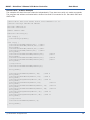
21 - Read Firmware Version
Read RoboClaw firmware version. Returns up to 32 bytes and is terminated by a null character.
Command syntax:
Sent: [Address, CMD]
Received: [“RoboClaw 10.2A v1.3.9, Checksum]
The command will return up to 32 bytes. The return string includes the product name and firmware
version. The return string is terminated with a null (0) character. This is done so the version
information can be read from a standard PC terminal window.
hserout [128, 21] ;read firmware version
hserin [Str VersionByte\32\0, Checksum]
24 - Read Main Battery Voltage Level
Read the main battery voltage level connected to B+ and B- terminals. The voltage is returned in 10ths
of a volt. Command syntax:
Sent: [Address, CMD]
Received: [Value.Byte1, Value.Byte0, Checksum]
The command will return 3 bytes. Byte 1 and 2 make up a word variable which is received MSB first
and is 10th of a volt. A returned value of 300 would equal 30V. Byte 3 is the checksum. It is calculated
the same way as sending a command and can be used to validate the data. The following example will
read the main battery voltage with RoboClaw address set to 128.
hserout [128, 24] ;read main battery voltage
hserin [Value.Byte1, Value.Byte0, Checksum]
25 - Read Logic Battery Voltage Level
Read a logic battery voltage level connected to LB+ and LB- terminals. The voltage is returned in 10ths
of a volt. Command syntax:
Sent: [Address, CMD]
Received: [Value.Byte1, Value.Byte0, Checksum]
The command will return 3 bytes. Byte 1 and 2 make up a word variable which is received MSB first
and is 10th of a volt. A returned value of 50 would equal 5V. Byte 3 is the checksum. It is calculated
the same way as sending a command and can be used to validate the data. The following example will
read the main battery voltage with RoboClaw address set to 128.
hserout [128, 25] ;read logic battery voltage
hserin [Value.Byte1, Value.Byte0, Checksum]
(c) 2010 BasicMicro. All Rights Reserved.
41
B0097 - RoboClaw 2 Channel 15A Motor Controller
Data Sheet
26 - Set Minimum Logic Voltage Level
Sets logic input (LB- / LB+) minimum voltage level. If the battery voltages drops below the set
voltage level RoboClaw will shut down. The value is cleared at start up and must set after each power
up. The voltage is set in .2 volt increments. A value of 0 sets the minimum value allowed which is 3V.
The valid data range is 0 - 120 (6V - 28V). The formula for calculating the voltage is: (Desired Volts 6) x 5 = Value. Examples of valid values are 3V = 0, 8V = 10 and 11V = 25. RoboClaw example with
address set to 128:
hserout [128, 26, 0, (154 & 0X7F)]
27 - Set Maximum Logic Voltage Level
Sets logic input (LB- / LB+) maximum voltage level. The valid data range is 0 - 144 (0V - 28V). By
setting the maximum voltage level RoboClaw will go into shut down and requires a hard reset to
recovers. The formula for calculating the voltage is: Desired Volts x 5.12 = Value. Examples of valid
values are 12V = 62, 16V = 82 and 24V = 123. RoboClaw example with address set to 128:
hserout [128, 27, 82, (213 & 0X7F)]
Main Battery Voltage Levels
The main battery levels are set in a similar way as the logic battery. See command 2 and 3 for details.
(c) 2010 BasicMicro. All Rights Reserved.
42
B0097 - RoboClaw 2 Channel 15A Motor Controller
Data Sheet
Quadrature Decoding
(c) 2010 BasicMicro. All Rights Reserved.
43
B0097 - RoboClaw 2 Channel 15A Motor Controller
Data Sheet
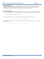
Quadrature Decoding
Handling the quadrature encoders is done using packet serial. All the switch settings still apply in to
enabling packet serial and setting the desired baud rates. See Mode - Packet Serial. The following
commands deal specifically with the dual quadrature decoders built into RoboClaw.
Checksum Calculation
All packet serial commands use a 7 bit checksum to prevent corrupt commands from being executed.
Since the RoboClaw expects a 7bit value the 8th bit is masked. The checksum is calculated as follows:
Address + Command + Data = Checksum
To mask the 8th bit you use can a simple math expression called AND as shown below:
Serout P15, i19200, [128, 0, 127, (255 & 0X7F)]
The hexadecimal value 0X7F is used to mask the 8th bit. You can also use a binary value of 01111111
as shown below:
Serout P15, i19200, [128, 0, 127, (255 & %01111111)]
(c) 2010 BasicMicro. All Rights Reserved.
44
B0097 - RoboClaw 2 Channel 15A Motor Controller
Data Sheet
Quadrature Encoder Wiring
RoboClaw can read two quadrature encoders. The encoders are connected to RoboClaw using CN4.
Both GND and 5 volts are present on the header to power the encoders.
In a two motor robot configuration one motor will spin clock wise (CW) while the other motor will spin
counter clock wise (CCW). The A and B inputs for one of the two encoders must be reversed as shown.
If either encoder is connected wrong one will count up and the other down this will cause commands
like mix drive forward to not work properly.
+1
A2
G3
B4
1+
2A
3G
4B
S1 S2 S3 +5V
2|1
R29
Robo Claw
R2
CTS
R1
Status1
Status2
R16 VD2 R15
Q14
C9
R9
C3
C4
R3
R7
R4 R6
U2
R30
R2
C1
CN4
C20
U4
C19
R17
R25
JP3
Y1
C2 C5
C14
C21
C22
R13
R28
CN5
R18
R32
VD3
JP2
JP1
+
ON
1 2 3 4 5 6 7 8 9 10
Error R5
Reset
B
C13
CN3
A
Power Sel
SW1
M1A
M1B
B+
B-
M2B
M2A
Basicmicro.com (c) 2009
(c) 2010 BasicMicro. All Rights Reserved.
45
B0097 - RoboClaw 2 Channel 15A Motor Controller
Data Sheet
Commands 16 - 20 Reading Quadrature Encoders
The following commands are used in dealing with the quadrature decoding counter registers. The
quadrature decoder is a simple counter that counts the incoming pulses, tracks the direction and
speed of each pulse. There are two registers one each for M1 and M2. (Note: A microcontroller with a
hardware UART is recommended for use with packet serial modes).
Command
Description
16
Read Quadrature Encoder Register for M1.
17
Read Quadrature Encoder Register for M2.
18
Read M1 Speed in Pulses Per Second.
19
Read M2 Speed in Pulses Per Second.
20
Resets Quadrature Encoder Registers for M1 and M2.
16 - Read Quadrature Encoder Register M1
Read decoder M1 counter. Since CMD 16 is a read command it does not require a checksum. However
a checksum value will be returned from RoboClaw and can be used to validate the data. Command
syntax:
Sent: [Address, CMD]
Received: [Value1.Byte3, Value1.Byte2, Value1.Byte1, Value1.Byte0, Value2,
Checksum]
The command will return 6 bytes. Byte 1,2,3 and 4 make up a long variable which is received MSB first
and represents the current count which can be any value from 0 - 4,294,967,295. Each pulse from the
quadrature encoder will increment or decrement the counter depending on the direction of rotation.
Byte 5 is the status byte for M1 decoder. It tracks counter underflow, direction, overflow and if the
encoder is operational. The byte value represents:
Bit0
Bit1
Bit2
Bit3
Bit4
Bit5
Bit6
Bit7
-
Counter Underflow (1= Underflow Occurred, Clear After Reading)
Direction (0 = Forward, 1 = Backwards)
Counter Overflow (1= Underflow Occurred, Clear After Reading)
Reserved
Reserved
Reserved
Reserved
Reserved
Byte 6 is the checksum. It is calculated the same way as sending a command. It can be used to
validate the resulting data. The following example will read M1 counter register, status byte and
checksum value with RoboClaw address set to 128.
hserout [128, 16] ;read command for M1 encoder
hserin [Value1.Byte3, Value1.Byte2, Value1.Byte1, Value1.Byte0, Value2, Checksum]
(c) 2010 BasicMicro. All Rights Reserved.
46
B0097 - RoboClaw 2 Channel 15A Motor Controller
Data Sheet
17 - Read Quadrature Encoder Register M2
Read decoder M2 counter. Since CMD 16 is a read command it does not require a checksum. However
a checksum value will be returned from RoboClaw and can be used to validate the data. Command
syntax:
Sent: [Address, CMD]
Received: [Value1.Byte3, Value1.Byte2, Value1.Byte1, Value1.Byte0, Value2, Checksum]
The command will return 6 bytes. Byte 1,2,3 and 4 make up a long variable which is received MSB first
and represents the current count which can be any value from 0 - 4,294,967,295. Each pulse from the
quadrature encoder will increment or decrement the counter depending on the direction of rotation.
Byte 5 is the status byte for M1 decoder. It tracks counter underflow, direction, overflow and if the
encoder is operational. The byte value represents:
Bit0
Bit1
Bit2
Bit3
Bit4
Bit5
Bit6
Bit7
-
Counter Underflow (1= Underflow Occurred, Clear After Reading)
Direction (0 = Forward, 1 = Backwards)
Counter Overflow (1= Underflow Occurred, Clear After Reading)
Reserved
Reserved
Reserved
Reserved
Reserved
Byte 6 is the checksum. It is calculated the same way as sending a command. It can be used to
validate the resulting data. The following example will read M1 counter register, status byte and
checksum value with RoboClaw address set to 128.
hserout [128, 17] ;read command for M2 encoder
hserin [Value1.Byte3, Value1.Byte2, Value1.Byte1, Value1.Byte0, Value2, Checksum]
18 - Read Speed M1
Read M1 counter speed. Returned value is in pulses per second. RoboClaw keeps track of how many
pulses received per second for both decoder channels. Since CMD 18 is a read command it does not
require a checksum to be sent. However a checksum value will be returned from RoboClaw and can be
used to validate the data. Command syntax:
Sent: [Address, CMD]
Received: [Value1.Byte3, Value1.Byte2, Value1.Byte1, Value1.Byte0, Value2, Checksum]
The command will return 6 bytes. Byte 1,2,3 and 4 make up a long variable which is received MSB
first and is the current ticks per second which can be any value from 0 - 4,294,967,295. Byte 5 is
the direction (0 – forward, 1 - backward). Byte 6 is the checksum. It is calculated the same way as
sending a command and can be used to validate the data. The following example will read M1 pulse
per second and direction with RoboClaw address set to 128.
hserout [128, 18] ;read command for M1 encoder
hserin [Value1.Byte3, Value1.Byte2, Value1.Byte1, Value1.Byte0, Value2, Checksum]
(c) 2010 BasicMicro. All Rights Reserved.
47
B0097 - RoboClaw 2 Channel 15A Motor Controller
Data Sheet
19 - Read Speed M2
Read M2 counter speed. Returned value is in pulses per second. RoboClaw keeps track of how many
pulses received per second for both decoder channels. Since CMD 19 is a read command it does not
require a checksum to be sent. However a checksum value will be returned from RoboClaw and can be
used to validate the data. Command syntax:
Sent: [Address, CMD]
Received: [Value1.Byte3, Value1.Byte2, Value1.Byte1, Value1.Byte0, Value2, Checksum]
The command will return 6 bytes. Byte 1,2,3 and 4 make up a long variable which is received MSB
first and is the current ticks per second which can be any value from 0 - 4,294,967,295. Byte 5 is
the direction (0 – forward, 1 - backward). Byte 6 is the checksum. It is calculated the same way as
sending a command and can be used to validate the data. The following example will read M2 pulse
per second and direction with RoboClaw address set to 128.
hserout [128, 19] ;read command for M2 encoder
hserin [Value1.Byte3, Value1.Byte2, Value1.Byte1, Value1.Byte0, Value2, Checksum]
20 - Reset Quadrature Encoder Counters
Will reset both quadrature decoder counters to zero. Since CMD 20 is a write command a checksum
value is required. Command syntax and example:
hserout [128, 20, (148 & %01111111)]; resets encoder registers
(c) 2010 BasicMicro. All Rights Reserved.
48
B0097 - RoboClaw 2 Channel 15A Motor Controller
Data Sheet
Commands 28 - 48 Motor Control by Quadrature Encoders
The following commands are used to control motor speeds, acceleration and distance using the
quadrature encoders. All speeds are given in quad pulses per second (QPPS) unless otherwise stated.
Quadrature encoders of different types and manufactures can be used. However many have different
resolutions and maximum speeds at which they operate. So each quadrature encoder will produce a
different range of pulses per second.
Command
Description
28
Set PID Constants for M1.
29
Set PID Constants for M2.
30
Read Current M1 Speed Resolution 125th of a Second.
31
Read Current M2 Speed Resolution 125th of a Second.
32
Drive M1 With Signed Duty Cycle.
33
Drive M2 With Signed Duty Cycle.
34
Mix Mode Drive M1 / M2 With Signed Duty Cycle.
35
Drive M1 With Signed Speed.
36
Drive M2 With Signed Speed.
37
Mix Mode Drive M1 / M2 With Signed Speed.
38
Drive M1 With Signed Speed And Acceleration.
39
Drive M2 With Signed Speed And Acceleration.
40
Mix Mode Drive M1 / M2 With Speed And Acceleration.
41
Drive M1 With Signed Speed And Distance. Buffered.
42
Drive M2 With Signed Speed And Distance. Buffered.
43
Mix Mode Drive M1 / M2 With Speed And Distance. Buffered.
44
Drive M1 With Signed Speed, Acceleration and Distance. Buffered.
45
Drive M2 With Signed Speed, Acceleration and Distance. Buffered.
46
Mix Mode Drive M1 / M2 With Speed, Acceleration And Distance. Buffered.
47
Read Buffer Length.
48
Set PWM Resolution.
(c) 2010 BasicMicro. All Rights Reserved.
49
B0097 - RoboClaw 2 Channel 15A Motor Controller
Data Sheet
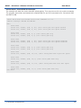
28 - Set PID Constants M1
Several motor and quadrature combinations can be used with RoboClaw. In some cases the default
PID values will need to be tuned for the systems being driven. This gives greater flexibility in what
motor and encoder combinations can be used. The RoboClaw PID system consist of four constants
starting with QPPS, P = Proportional, I= Integral and D= Derivative. The defaults values are:
QPPS = 44000
P = 0x00010000
I = 0x00008000
D = 0x00004000
QPPS is the speed of the encoder when the motor is at 100% power. P, I, D are the default values
used after a reset. Command syntax:
Sent: [Address, CMD, D(4 bytes), P(4 bytes), I(4 bytes), QPPS(4 byte), Checksum]
Each value is made up of 4 bytes for a long. To write the registers a checksum value is used. This
prevents an accidental write.
29 - Set PID Constants M2
Several motor and quadrature combinations can be used with RoboClaw. In some cases the default
PID values will need to be tuned for the systems being driven. This gives greater flexibility in what
motor and encoder combinations can be used. The RoboClaw PID system consist of four constants
starting with QPPS, P = Proportional, I= Integral and D= Derivative. The defaults values are:
QPPS = 44000
P = 0x00010000
I = 0x00008000
D = 0x00004000
QPPS is the speed of the encoder when the motor is at 100% power. P, I, D are the default values
used after a reset. Command syntax:
Sent: [Address, CMD, D(4 bytes), P(4 bytes), I(4 bytes), QPPS(4 byte), Checksum]
Each value is made up of 4 bytes for a long. To write the registers a checksum value is used. This prevents
an accidental write.
(c) 2010 BasicMicro. All Rights Reserved.
50
B0097 - RoboClaw 2 Channel 15A Motor Controller
Data Sheet
30 - Read Current Speed M1
Read the current pulse per 125th of a second. This is a high resolution version of command 18 and
19. Command 30 can be used to make a independent PID routine. The resolution of the command
is required to create a PID routine using any microcontroller or PC used to drive RoboClaw. The
command syntax:
Sent: [Address, CMD]
Received: [Value1.Byte3, Value1.Byte2, Value1.Byte1, Value1.Byte0, Value2, Checksum]
The command will return 5 bytes, MSB sent first for a long. The first 4 bytes are a 32 byte value
(long) that repersent the speed. The 5th byte (Value2) is direction (0 – forward, 1 - backward). is A
checksum is returned in order to validate the data returned.
31 - Read Current Speed M2
Read the current pulse per 125th of a second. This is a high resolution version of command 18 and
19. Command 31 can be used to make a independent PID routine. The resolution of the command
is required to create a PID routine using any microcontroller or PC used to drive RoboClaw. The
command syntax:
Sent: [Address, CMD]
Received: [Value1.Byte3, Value1.Byte2, Value1.Byte1, Value1.Byte0, Value2, Checksum]
The command will return 5 bytes, MSB sent first for a long. The first 4 bytes are a 32 byte value
(long) that repersent the speed. The 5th byte (Value2) is direction (0 – forward, 1 - backward). is A
checksum is returned in order to validate the data returned.
32 - Drive M1 With Signed Duty Cycle
Drive M1 using a duty cycle value. The default PWM is 8bit resolution. The default value can be
changed see CMD 48. The duty cycle is used to control the speed of the motor without a quadrature
encoder. A value used to drive one motor at 50% will be differ from one motor to the next. The
command syntax:
Sent: [Address, CMD, Duty(2 Bytes), Checksum]
The duty value is signed and the default range is 8bits. The default PWM resolution can be changed
for more range. To change the resolution see command 48.
33 - Drive M2 With Signed Duty Cycle
Drive M2 using a duty cycle value. The default PWM is 8bit resolution. The default value can be
changed see CMD 48. The duty cycle is used to control the speed of the motor without a quadrature
encoder. A value used to drive one motor at 50% will be differ from one motor to the next. The
command syntax:
Sent: [Address, CMD, Duty(2 Bytes), Checksum]
The duty value is signed and the default range is 8bits. The default PWM resolution can be changed
for more range. To change the resolution see command 48.
(c) 2010 BasicMicro. All Rights Reserved.
51
B0097 - RoboClaw 2 Channel 15A Motor Controller
Data Sheet
34 - Mix Mode Drive M1 / M2 With Signed Duty Cycle
Drive both M1 and M2 using a duty cycle value. The default PWM is 8bit resolution. The default
value can be changed see CMD 48. The duty cycle is used to control the speed of the motor without
a quadrature encoder. A value used to drive one motor at 50% will be differ from one motor to the
next. The command syntax:
Sent: [Address, CMD, DutyM1(2 Bytes), DutyM2(2 Bytes), Checksum]
The duty value is signed and the default range is 8bits. The default PWM resolution can be changed
for more range. To change the resolution see command 48.
35 - Drive M1 With Signed Speed
Drive M1 using a speed value. The sign indicates which direction the motor will turn. This command
is used to drive the motor by quad pulses per second. Different quadrature encoders will have
different rates at which they generate the incoming pulses. The values used will differ from one
encoder to another. Once a value is sent the motor will begin to accelerate as fast as possible until
the defined rate is reached. The command syntax:
Sent: [Address, CMD, Qspeed(4 Bytes), Checksum]
4 Bytes (long) are used to express the pulses per second. Quadrature encoders send 4 pulses per
tick. So 1000 ticks would be counted as 4000 pulses.
36 - Drive M2 With Signed Speed
Drive M2 with a speed value. The sign indicates which direction the motor will turn. This command is
used to drive the motor by quad pulses per second. Different quadrature encoders will have different
rates at which they generate the incoming pulses. The values used will differ from one encoder to
another. Once a value is sent, the motor will begin to accelerate as fast as possible until the rate
defined is reached. The command syntax:
Sent: [Address, CMD, Qspeed(4 Bytes), Checksum]
4 Bytes (long) are used to expressed the pulses per second. Quadrature encoders send 4 pulses per
tick. So 1000 ticks would be counted as 4000 pulses.
(c) 2010 BasicMicro. All Rights Reserved.
52
B0097 - RoboClaw 2 Channel 15A Motor Controller
Data Sheet
37 - Mix Mode Drive M1 / M2 With Signed Speed
Drive M1 and M2 in the same command using a signed speed value. The sign indicates which direction
the motor will turn. This command is used to drive both motors by quad pulses per second. Different
quadrature encoders will have different rates at which they generate the incoming pulses. The values
used will differ from one encoder to another. Once a value is sent the motor will begin to accelerate as
fast as possible until the rate defined is reached. The command syntax:
Sent: [Address, CMD, QspeedM1(4 Bytes), QspeedM2(4 Bytes), Checksum]
4 Bytes (long) are used to express the pulses per second. Quadrature encoders send 4 pulses per tick.
So 1000 ticks would be counted as 4000 pulses.
38 - Drive M1 With Signed Speed And Acceleration
Drive M1 with a signed speed and acceleration value. The sign indicates which direction the motor
will run. The acceleration values are not signed. This command is used to drive the motor by quad
pulses per second and using an acceleration value for ramping. Different quadrature encoders will
have different rates at which they generate the incoming pulses. The values used will differ from one
encoder to another. Once a value is sent the motor will begin to accelerate incrementally until the rate
defined is reached. The command syntax:
Sent: [Address, CMD, Accel(4 Bytes), Qspeed(4 Bytes), Checksum]
4 Bytes (long) are used to express the pulses per second. Quadrature encoders send 4 pulses per tick.
So 1000 ticks would be counted as 4000 pulses. The acceleration is measured in speed per second.
An acceleration value of 12,000 QPPS with a speed of 12,000 QPPS would accelerate a motor from 0
to 12,000 QPPS in 1 second. Another example would be an acceleration value of 24,000 QPPS and a
speed value of 12,000 QPPS would accelerate the motor to 12,000 QPPS in 0.5 seconds.
39 - Drive M2 With Signed Speed And Acceleration
Drive M2 with a signed speed and acceleration value. The sign indicates which direction the motor will
run. The acceleration value is not signed. This command is used to drive the motor by quad pulses per
second and using an acceleration value for ramping. Different quadrature encoders will have different
rates at which they generate the incoming pulses. The values used will differ from one encoder to
another. Once a value is sent the motor will begin to accelerate incrementally until the rate defined is
reached. The command syntax:
Sent: [Address, CMD, Accel(4 Bytes), Qspeed(4 Bytes), Checksum]
4 Bytes (long) are used to express the pulses per second. Quadrature encoders send 4 pulses per tick.
So 1000 ticks would be counted as 4000 pulses. The acceleration is measured in speed per second.
An acceleration value of 12,000 QPPS with a speed of 12,000 QPPS would accelerate a motor from 0
to 12,000 QPPS in 1 second. Another example would be an acceleration value of 24,000 QPPS and a
speed value of 12,000 QPPS would accelerate the motor to 12,000 QPPS in 0.5 seconds.
(c) 2010 BasicMicro. All Rights Reserved.
53
B0097 - RoboClaw 2 Channel 15A Motor Controller
Data Sheet
40 - Mix Mode Drive M1 / M2 With Speed And Acceleration
Drive M1 and M2 in the same command using one value for acceleration and two signed speed values
for each motor. The sign indicates which direction the motor will run. The acceleration value is not
signed. The motors are sync during acceleration. This command is used to drive the motor by quad
pulses per second and using an acceleration value for ramping. Different quadrature encoders will
have different rates at which they generate the incoming pulses. The values used will differ from one
encoder to another. Once a value is sent the motor will begin to accelerate incrementally until the rate
defined is reached. The command syntax:
Sent: [Address, CMD, Accel(4 Bytes), QspeedM1(4 Bytes), QspeedM2(4 Bytes), Checksum]
4 Bytes (long) are used to express the pulses per second. Quadrature encoders send 4 pulses per tick.
So 1000 ticks would be counted as 4000 pulses. The acceleration is measured in speed per second.
An acceleration value of 12,000 QPPS with a speed of 12,000 QPPS would accelerate a motor from 0
to 12,000 QPPS in 1 second. Another example would be an acceleration value of 24,000 QPPS and a
speed value of 12,000 QPPS would accelerate the motor to 12,000 QPPS in 0.5 seconds.
41 - Buffered M1 Drive With Signed Speed And Distance
Drive M1 with a signed speed and distance value. The sign indicates which direction the motor will run.
The distance value is not signed. This command is buffered. This command is used to control the top
speed and total distance traveled by the motor. Each motor channel M1 and M2 have separate buffers.
This command will execute immediately if no other command for that channel is executing, otherwise
the command will be buffered in the order it was sent. Any buffered or executing command can be
stopped when a new command is issued by setting the Buffer argument. All values used are in quad
pulses per second. The command syntax:
Sent: [Address, CMD, QSpeed(4 Bytes), Distance(4 Bytes), Buffer(1 Byte), Checksum]
4 Bytes(long) are used to express the pulses per second. The Buffer argument can be set to a 1 or 0.
If a value of 0 is used the command will be buffered and executed in the order sent. If a value of 1 is
used the current running command is stopped, any other commands in the buffer are deleted and the
new command is executed.
42 - Buffered M2 Drive With Signed Speed And Distance
Drive M2 with a speed and distance value. The sign indicates which direction the motor will run. The
distance value is not signed. This command is buffered. Each motor channel M1 and M2 have separate
buffers. This command will execute immediately if no other command for that channel is executing,
otherwise the command will be buffered in the order it was sent. Any buffered or executing command
can be stopped when a new command is issued by setting the Buffer argument. All values used are in
quad pulses per second. The command syntax:
Sent: [Address, CMD, QSpeed(4 Bytes), Distance(4 Bytes), Buffer(1 Byte), Checksum]
4 Bytes(long) are used to express the pulses per second. The Buffer argument can be set to a 1 or 0.
If a value of 0 is used the command will be buffered and executed in the order sent. If a value of 1 is
used the current running command is stopped, any other commands in the buffer are deleted and the
new command is executed.
(c) 2010 BasicMicro. All Rights Reserved.
54
B0097 - RoboClaw 2 Channel 15A Motor Controller
Data Sheet
43 - Buffered Mix Mode Drive M1 / M2 With Signed Speed And Distance
Drive M1 and M2 with a speed and distance value. The sign indicates which direction the motor will
run. The distance value is not signed. This command is buffered. Each motor channel M1 and M2
have separate buffers. This command will execute immediately if no other command for that channel
is executing, otherwise the command will be buffered in the order it was sent. Any buffered or
executing command can be stopped when a new command is issued by setting the Buffer argument.
All values used are in quad pulses per second. The command syntax:
Sent: [Address, CMD, QSpeedM1(4 Bytes), DistanceM1(4 Bytes),
QSpeedM2(4 Bytes), DistanceM2(4 Bytes), Buffer(1 Byte), Checksum]
4 Bytes(long) are used to express the pulses per second. The Buffer argument can be set to a 1 or 0.
If a value of 0 is used the command will be buffered and executed in the order sent. If a value of 1 is
used the current running command is stopped, any other commands in the buffer are deleted and the
new command is executed.
44 - Buffered M1 Drive With Signed Speed, Accel And Distance
Drive M1 with a speed, acceleration and distance value. The sign indicates which direction the motor
will run. The acceleration and distance values are not signed. This command is used to control the
motors top speed, total distanced traveled and at what incremental acceleration value to use until
the top speed is reached. Each motor channel M1 and M2 have separate buffers. This command will
execute immediately if no other command for that channel is executing, otherwise the command will
be buffered in the order it was sent. Any buffered or executing command can be stopped when a new
command is issued by setting the Buffer argument. All values used are in quad pulses per second. The
command syntax:
Sent: [Address, CMD, Accel(4 bytes), QSpeed(4 Bytes), Distance(4 Bytes),
Buffer(1 Byte), Checksum]
4 Bytes(long) are used to express the pulses per second. The Buffer argument can be set to a 1 or 0.
If a value of 0 is used the command will be buffered and executed in the order sent. If a value of 1 is
used the current running command is stopped, any other commands in the buffer are deleted and the
new command is executed.
45 - Buffered M2 Drive With Signed Speed, Accel And Distance
Drive M2 with a speed, acceleration and distance value. The sign indicates which direction the motor
will run. The acceleration and distance values are not signed. This command is used to control the
motors top speed, total distanced traveled and at what incremental acceleration value to use until
the top speed is reached. Each motor channel M1 and M2 have separate buffers. This command will
execute immediately if no other command for that channel is executing, otherwise the command will
be buffered in the order it was sent. Any buffered or executing command can be stopped when a new
command is issued by setting the Buffer argument. All values used are in quad pulses per second. The
command syntax:
Sent: [Address, CMD, Accel(4 bytes), QSpeed(4 Bytes), Distance(4 Bytes),
Buffer(1 Byte), Checksum]
4 Bytes(long) are used to express the pulses per second. The Buffer argument can be set to a 1 or 0.
If a value of 0 is used the command will be buffered and executed in the order sent. If a value of 1 is
used the current running command is stopped, any other commands in the buffer are deleted and the
new command is executed.
(c) 2010 BasicMicro. All Rights Reserved.
55
B0097 - RoboClaw 2 Channel 15A Motor Controller
Data Sheet
46 - Buffered Mix Mode Drive M1 / M2 With Signed Speed, Accel And Distance
Drive M1 and M2 with a speed, acceleration and distance value. The sign indicates which direction the
motor will run. The acceleration and distance values are not signed. This command is used to control
both motors top speed, total distanced traveled and at what incremental acceleration value to use
until the top speed is reached. Each motor channel M1 and M2 have separate buffers. This command
will execute immediately if no other command for that channel is executing, otherwise the command
will be buffered in the order it was sent. Any buffered or executing command can be stopped when a
new command is issued by setting the Buffer argument. All values used are in quad pulses per second.
The command syntax:
Sent: [Address, CMD, Accel(4 Bytes), QSpeedM1(4 Bytes), DistanceM1(4 Bytes),
QSpeedM2(4 bytes), DistanceM2(4 Bytes), Buffer(1 Byte), Checksum]
4 Bytes(long) are used to express the pulses per second. The Buffer argument can be set to a 1 or 0.
If a value of 0 is used the command will be buffered and executed in the order sent. If a value of 1 is
used the current running command is stopped, any other commands in the buffer are deleted and the
new command is executed.
47 - Read Buffer Length
Read both motor M1 and M2 buffer lengths. This command can be used to determine how many
commands are waiting to execute.
Sent: [Address, CMD]
Received: [BufferM1(1 Bytes), BufferM2(1 Bytes), Checksum]
The return values represent how many commands per buffer are waiting to be executed. The
maximum buffer size per motor is 31 commands.
(c) 2010 BasicMicro. All Rights Reserved.
56
B0097 - RoboClaw 2 Channel 15A Motor Controller
Data Sheet
Reading Quadrature Encoder - Arduino Example
The example was tested with an Arduino Uno. RoboClaw was connected as shown in both packet serial
wiring and quadrature encoder wiring diagrams.
The example will read the speed, total ticks and direction of each encoder. Connect to the program
using a terminal window set to 38400 baud. The program will display the values of each encoders
current count along with each encoder status bit in binary and the direction bit. As the encoder is
turned it will update the screen.
//Basic Micro Robo Claw Packet Serial Mode.
//Switch settings: SW3=ON, SW4=ON, SW5=ON
#include “BMSerial.h”
#include “RoboClaw.h”
#define address 0x80
#define
#define
#define
#define
Kp 0x00010000
Ki 0x00008000
Kd 0x00004000
qpps 44000
BMSerial terminal(0,1);
RoboClaw roboclaw(5,6);
void setup() {
terminal.begin(38400);
roboclaw.begin(38400);
}
roboclaw.SetM1Constants(address,Kd,Kp,Ki,qpps);
roboclaw.SetM2Constants(address,Kd,Kp,Ki,qpps);
void loop() {
uint8_t status;
bool valid;
uint32_t enc1= roboclaw.ReadEncM1(address, &status, &valid);
if(valid){
terminal.print(“Encoder1:”);
terminal.print(enc1,HEX);
terminal.print(“ “);
terminal.print(status,HEX);
terminal.print(“ “);
}
uint32_t enc2 = roboclaw.ReadEncM2(address, &status, &valid);
if(valid){
terminal.print(“Encoder2:”);
terminal.print(enc2,HEX);
terminal.print(“ “);
terminal.print(status,HEX);
terminal.print(“ “);
}
uint32_t speed1 = roboclaw.ReadSpeedM1(address, &status, &valid);
if(valid){
terminal.print(“Speed1:”);
terminal.print(speed1,HEX);
terminal.print(“ “);
}
uint32_t speed2 = roboclaw.ReadSpeedM2(address, &status, &valid);
if(valid){
terminal.print(“Speed2:”);
terminal.print(speed2,HEX);
terminal.print(“ “);
}
terminal.println();
delay(100);
}
(c) 2010 BasicMicro. All Rights Reserved.
57
B0097 - RoboClaw 2 Channel 15A Motor Controller
Data Sheet
Speed Controlled by Quadrature Encoders - Arduino Example
The following example was written using an BasicATOM Pro. RoboClaw was connected as shown in both
packet serial wiring and quadrature encoder wiring diagrams.
The example will command a 4wheel robot to move forward, backward, right turn and left turn slowly.
You can change the speed by adjusting the value of Speed and Speed2 variables.
//Basic Micro Robo Claw Packet Serial Mode.
//Switch settings: SW3=ON, SW4=ON, SW5=ON
#include “BMSerial.h”
#include “RoboClaw.h”
#define address 0x80
#define
#define
#define
#define
Kp 0x00010000
Ki 0x00008000
Kd 0x00004000
qpps 44000
BMSerial terminal(0,1);
RoboClaw roboclaw(5,6);
void setup() {
terminal.begin(38400);
roboclaw.begin(38400);
roboclaw.SetM1Constants(address,Kd,Kp,Ki,qpps);
roboclaw.SetM2Constants(address,Kd,Kp,Ki,qpps);
}
void displayspeed(void)
{
uint8_t status;
bool valid;
uint32_t enc1= roboclaw.ReadEncM1(address, &status, &valid);
if(valid){
terminal.print(“Encoder1:”);
terminal.print(enc1,DEC);
terminal.print(“ “);
terminal.print(status,HEX);
terminal.print(“ “);
}
uint32_t enc2 = roboclaw.ReadEncM2(address, &status, &valid);
if(valid){
terminal.print(“Encoder2:”);
terminal.print(enc2,DEC);
terminal.print(“ “);
terminal.print(status,HEX);
terminal.print(“ “);
}
(c) 2010 BasicMicro. All Rights Reserved.
58
B0097 - RoboClaw 2 Channel 15A Motor Controller
Data Sheet
uint32_t speed1 = roboclaw.ReadSpeedM1(address, &status, &valid);
if(valid){
terminal.print(“Speed1:”);
terminal.print(speed1,DEC);
terminal.print(“ “);
}
uint32_t speed2 = roboclaw.ReadSpeedM2(address, &status, &valid);
if(valid){
terminal.print(“Speed2:”);
terminal.print(speed2,DEC);
terminal.print(“ “);
}
terminal.println();
}
void loop() {
roboclaw.SpeedAccelDistanceM1(address,12000,12000,48000);
uint8_t depth1,depth2;
do{
displayspeed();
roboclaw.ReadBuffers(address,depth1,depth2);
}while(depth1);
roboclaw.SpeedAccelDistanceM1(address,12000,-12000,48000);
do{
displayspeed();
roboclaw.ReadBuffers(address,depth1,depth2);
}while(depth1);
}
(c) 2010 BasicMicro. All Rights Reserved.
59
B0097 - RoboClaw 2 Channel 15A Motor Controller
Data Sheet
Reading Quadrature Encoder - BasicATOM Pro Example
The example was tested with a BasicATOM Pro. RoboClaw was connected as shown in both packet
serial wiring and quadrature encoder wiring diagrams.
The example will read the speed, total ticks and direction of each encoder. Connect to the program
using the Basic Micro Studio terminal window set to 38400 baud. The program will display the values of
each encoders current count along with each encoder status bit in binary and the direction bit. As the
encoder is turned it will update the screen.
Encoder1 Var Long
Encoder2 Var Long
Status Var Byte
CRC Var Byte
ENABLEHSERIAL
;used on AtomPro24 and AtomPro28. AtomPro40 and ARC-32 use EnableHSerial2
SetHSerial H38400,H8DATABITS,HNOPARITY,H1STOPBITS
Pause 250
Hserout [128, 20, (148 & 0x7F)]; Resets encoder registers
Main
Pause 100
ReadEncoderM1
Hserout [128, 16]
Hserin [Encoder1.byte3, Encoder1.Byte2, Encoder1.Byte1, Encoder1.Byte0, Status, crc]
Serout s_out, i38400, [0,”Encoder1: “, SDEC Encoder1, 13, “Status Byte: “, BIN Status]
ReadSpeedM1
Hserout [128, 18]
Hserin [Encoder1.byte3, Encoder1.Byte2, Encoder1.Byte1, Encoder1.Byte0, Status, crc]
Serout s_out, i38400, [13, 13, “Speed: “, DEC Encoder1, 13, “Direction: “, DEC Status]
ReadEncoderM2
Hserout [128, 17]
Hserin [Encoder2.byte3, Encoder2.Byte2, Encoder2.Byte1, Encoder2.Byte0, Status, crc]
Serout s_out, i38400, [13, 13, “Encoder2: “, SDEC Encoder2, 13, “Status Byte: “, BIN Status]
ReadSpeedM2
Hserout [128, 19]
Hserin [Encoder2.byte3, Encoder2.Byte2, Encoder2.Byte1, Encoder2.Byte0, Status, crc]
Serout s_out, i38400, [13, 13, “Speed: “, DEC Encoder2, 13, “Direction: “, DEC Status]
Goto Main
(c) 2010 BasicMicro. All Rights Reserved.
60
B0097 - RoboClaw 2 Channel 15A Motor Controller
Data Sheet
Speed Controlled by Quadrature Encoders - BasicATOM Pro Example
The following example was written using an BasicATOM Pro. RoboClaw was connected as shown in both
packet serial wiring and quadrature encoder wiring diagrams.
The example will command a 4wheel robot to move forward, backward, right turn and left turn slowly.
You can change the speed by adjusting the value of Speed and Speed2 variables.
CMD
Speed
Speed2
CRC
Address
var
var
var
var
con
byte
long
long
byte
128
ENABLEHSERIAL ;used on AtomPro24 and AtomPro28. AtomPro40 and ARC-32 use EnableHSerial2
SetHSerial H38400,H8DATABITS,HNOPARITY,H1STOPBITS
Mixed_Forward
CMD=37
Speed=12000
Speed2=12000
CRC = (address + cmd + speed.byte3 + speed.byte2 + speed.byte1 + speed.byte0 + |
speed2.byte3 + speed2.byte2 + speed2.byte1 + speed2.byte0)&0x7F
hserout [address,cmd,speed.byte3,speed.byte2,speed.byte1,speed.byte0, |
speed2.byte3,speed2.byte2,speed2.byte1,speed2.byte0,crc]
pause 4000
Mixed_Backward
CMD=37
Speed=-12000
Speed2=-12000
CRC = (address + cmd + speed.byte3 + speed.byte2 + speed.byte1 + speed.byte0 + |
speed2.byte3 + speed2.byte2 + speed2.byte1 + speed2.byte0)&0x7F
hserout [address,cmd,speed.byte3,speed.byte2,speed.byte1,speed.byte0, |
speed2.byte3,speed2.byte2,speed2.byte1,speed2.byte0,crc]
pause 4000
Mixed_Left
CMD=37
Speed=-12000
Speed2=12000
CRC = (address + cmd + speed.byte3 + speed.byte2 + speed.byte1 + speed.byte0 + |
speed2.byte3 + speed2.byte2 + speed2.byte1 + speed2.byte0)&0x7F
hserout [address,cmd,speed.byte3,speed.byte2,speed.byte1,speed.byte0, |
speed2.byte3,speed2.byte2,speed2.byte1,speed2.byte0,crc]
pause 4000
Mixed_Right
CMD=37
Speed=12000
Speed2=-12000
CRC = (address + cmd + speed.byte3 + speed.byte2 + speed.byte1 + speed.byte0 + |
speed2.byte3 + speed2.byte2 + speed2.byte1 + speed2.byte0)&0x7F
hserout [address,cmd,speed.byte3,speed.byte2,speed.byte1,speed.byte0, |
speed2.byte3,speed2.byte2,speed2.byte1,speed2.byte0,crc]
pause 4000
Mixed_Stop
CMD=37
Speed=0
Speed2=0
CRC = (address + cmd + speed.byte3 + speed.byte2 + speed.byte1 + speed.byte0 + |
speed2.byte3 + speed2.byte2 + speed2.byte1 + speed2.byte0)&0x7F
hserout [address,cmd,speed.byte3,speed.byte2,speed.byte1,speed.byte0, |
speed2.byte3,speed2.byte2,speed2.byte1,speed2.byte0,crc]
stop
(c) 2010 BasicMicro. All Rights Reserved.
61
B0097 - RoboClaw 2 Channel 15A Motor Controller
Data Sheet
Electrical Characteristics
Characteristic
Rating
Min
Pulse Per Second
PPS
0
Main Battery (B+ / B-)
VDC
6
24
30
Logic Battery (LB+ / LB-)
VDC
6
12
30
External Current Draw (BEC)
Logic Circuit
Motor Current Per Channel
90
A
15
I/O Logic
TTL
(c) 2010 BasicMicro. All Rights Reserved.
3A
mA
VDC
C
Max
8,000,000
A
I/O Voltages
Tempature Range
Typ
0
30
5
5
-40
+125
62
B0097 - RoboClaw 2 Channel 15A Motor Controller
Data Sheet
Warranty
Basic Micro warranties its products against defects in material and workmanship for a period of
90 days. If a defect is discovered, Basic Micro will, at our discretion, repair, replace, or refund the
purchase price of the product in question. Contact us at [email protected]. No returns will be
accepted without the proper authorization.
Copyrights and Trademarks
Copyright© 2010 by Basic Micro, Inc. All rights reserved. PICmicro® is a trademark of Microchip
Technology, Inc. The Basic Atom and Basic Micro are registered trademarks of Basic Micro Inc. Other
trademarks mentioned are registered trademarks of their respective holders.
Disclaimer
Basic Micro cannot be held responsible for any incidental, or consequential damages resulting from
use of products manufactured or sold by Basic Micro or its distributors. No products from Basic Micro
should be used in any medical devices and/or medical situations. No product should be used in a life
support situation.
Contacts
Email: [email protected]
Tech support: [email protected]
Web: http://www.basicmicro.com
Discussion List
A web based discussion board is maintained at http://www.basicmicro.com.
Technical Support
Technical support is made available by sending an email to [email protected]. All email will
be answered within 48 hours. All general syntax and programming questions, unless deemed to be a
software issue, will be referred to the on-line discussion forums.
(c) 2010 BasicMicro. All Rights Reserved.
63
!
!""#$%&'()(*+,(
!
!""#$%&'()(*+,(
®
MB1000
™
LV-MaxSonar -EZ0 Pin Out
GND – Return for the DC power supply. GND (& Vcc) must be
ripple and noise free for best operation.
+5V – Vcc – Operates on 2.5V - 5.5V. Recommended current
capability of 3mA for 5V, and 2mA for 3V.
TX – When the *BW is open or held low, the TX output delivers
®
™
LV-MaxSonar -EZ0 Circuit
®
™
The LV-MaxSonar -EZ0 sensor functions
using active components consisting of an LM324,
a diode array, a PIC16F676, together with a
variety of passive components.
asynchronous serial with an RS232 format, except voltages are 0-Vcc.
The output is an ASCII capital “R”, followed by three ASCII character
digits representing the range in inches up to a maximum of 255,
followed by a carriage return (ASCII 13). The baud rate is 9600, 8
bits, no parity, with one stop bit. Although the voltage of 0-Vcc is
outside the RS232 standard, most RS232 devices have sufficient
margin to read 0-Vcc serial data. If standard voltage level RS232 is
desired, invert, and connect an RS232 converter such as a MAX232.
When BW pin is held high the TX output sends a single pulse, suitable
for low noise chaining. (no serial data).
™
RX – This pin is internally pulled high. The EZ0 will continually
measure range and output if RX data is left unconnected or held high.
™
If held low, the EZ0 will stop ranging. Bring high for 20uS or more
to command a range reading.
AN – Outputs analog voltage with a scaling factor of (Vcc/512) per
inch. A supply of 5V yields ~9.8mV/in. and 3.3V yields ~6.4mV/in.
The output is buffered and corresponds to the most recent range data.
PW – This pin outputs a pulse width representation of range. The
distance can be calculated using the scale factor of 147uS per inch.
BW – *Leave open or hold low for serial output on the TX output.
When BW pin is held high, the TX output sends a pulse (instead of
serial data), suitable for low noise chaining.
®
™
LV-MaxSonar -EZ0 Timing Description
®
™
250mS after power-up, the LV-MaxSonar -EZ0 is ready to accept the RX command. If the RX pin is left open or held
high, the sensor will first run a calibration cycle (49mS), and then it will take a range reading (49mS). After the power up
®
™
delay, the first reading will take an additional ~100mS. Subsequent readings will take 49mS. The LV-MaxSonar -EZ0
checks the RX pin at the end of every cycle. Range data can be acquired once every 49mS.
®
™
Each 49mS period starts by the RX being high or open, after which the LV-MaxSonar -EZ0 sends thirteen 42KHz
waves, after which the pulse width pin (PW) is set high. When a target is detected the PW pin is pulled low. The PW pin is
high for up to 37.5mS if no target is detected. The remainder of the 49mS time (less 4.7mS) is spent adjusting the analog
voltage to the correct level. When a long distance is measured immediately after a short distance reading, the analog
voltage may not reach the exact level within one read cycle. During the last 4.7mS, the serial data is sent. The LV®
™
MaxSonar -EZ0 timing is factory calibrated to one percent at five volts, and in use is better than two percent. In addition,
operation at 3.3V typically causes the objects range, to be reported, one to two percent further than actual.
®
™
LV-MaxSonar -EZ0 General Power-Up Instruction
®
™
Each time after the LV-MaxSonar -EZ0 is powered up, it will calibrate during its first read cycle. The sensor uses this
stored information to range a close object. It is important that objects not be close to the sensor during this calibration
cycle. The best sensitivity is obtained when it is clear for fourteen inches, but good results are common when clear for at
least seven inches. If an object is too close during the calibration cycle, the sensor may then ignore objects at that distance.
®
™
The LV-MaxSonar -EZ0 does not use the calibration data to temperature compensate for range, but instead to
compensate for the sensor ringdown pattern. If the temperature, humidity, or applied voltage changes during operation, the
sensor may require recalibration to reacquire the ringdown pattern. Unless recalibrated, if the temperature increases, the
sensor is more likely to have false close readings. If the temperature decreases, the sensor is more likely to have reduced up
®
™
close sensitivity. To recalibrate the LV-MaxSonar -EZ0 , cycle power, then command a read cycle.
Product / specifications subject to change without notice. For more info visit www.maxbotix.com
®
MaxBotix
Inc.
MaxBotix, MaxSonar & EZ0 are trademarks of MaxBotix Inc.
LV-EZ0™ • patent 7,679,996 • Copyright 2005 – 2012
3#4156
!"#$%& $'()*"#+,)-$+./)"
01,&
222."#+,)-$+./)"
3789998
!""#$%&'(()(*+,(
!
Discharge Curve
Charging Curve
SP E C I F I C AT I O N O F G BS-L F P20A H
Single cell charging!3.8V
Nominal Capacity
20Ah
Working Voltage
Battery pack charging!3.6V
Single cell charging!2.5V
Battery pack discharging!2.8V
Max. Charging Current
Standard Charging Current
Internal Resistance
"3C
0.3~0.8C
"2.5m#
Max. Discharging
Current
Continuous Current!"3C
Impulse Current!"10C
Best Charging Current
Cycle Life
0.5C
Single cell $1500 times
%80%D O D&
Battery pack$1200 times
%80%D O D&
Charging!(0'!
Temp. resistance of Shell
"135'
Working Temperature
Discharging!-2"'#$%'!
0.75kg±100g
Self Discharge rate ( month)
"3%
Cell Weight
(800w/kg
Energy Density
Single Cell Dimension
!
85~100Wh/kg
Power Density
71mm*42mm*152mm
!
!""#$%&'()(*+,(
Tenergy Corporation
!
!
!!!!!!!!!!!!!
436 Kato Terrace
Fremont, CA 94539
Tel: 510.687-0388 Fax: 510.687.0328
)))"*&+&,%-.$//&,-"0'1!!!&1$234!5$3&56/&+&,%-7$//&,-"0'1!
3!
!PCB Layout
Top Layout
Bottom Layout
Top Overlay
Bottom Overlay
Terminals:
1. B4: Connect to the forth battery’s positive terminal
2. B3: Connect to the third battery’s positive terminal
3. B2: Connect to the second battery’s positive terminal
4. B1: Connect to the first battery’s positive terminal
5. B0: Connect to the first battery’s negative terminal
6. B-: Connect to the first battery’s negative terminal
7. P-: Connect to the battery’s output or the charger’s negative terminal
Specifications and data are subject to change without notice. Contact Tenergy for latest information.
©2010 Tenergy Corporation. All rights reserved"!!!!!!!!!!!!!!!!!!!!!!!!!!!!!!!!!!!!!!!!!!!!!!!!!!!!!!!!!!!!!!!!!!!!!!!!!!!!!!!!!!!!!!!!!!!#$%&!!!'(!!!
Appendix F [7] Features:
x
x
x
x
x
x
x
Intelligent charger designed for 4 cell LiFePO4 battery packs.
CPU control and pulse width modulation (PWM) technology, charging current and output
voltage is controlled accurately to ensure fully-charged and avoid over-charging.
Built-in cooling fan to ensure charger long service life.
Safety protection:
o Over Voltage Protection
o Short Circuit Protection
o Output Reverse Protection
Charging time:
o Charging Time= (1.41 * Ah rate of the pack) / 10A charge current
Built-in IC to cut-off power automatically when battery is fully charged.
LED indicators:
o LED 1 = Red = Power On
o LED 2 = Red = Charging
o LED 3 = Green = Fully Charged
User Instructions:
Check the output plug of this charger and make sure it is not loose.
Before charging, please connect the charger's alligator clips to battery
first: the "red" clip connects to the POSITIVE pole and the "black"
connects to the NEGATIVE pole. After, connect the input power plug to
the indoor power supply.
The charger applies the intelligent charging method of constant current
and constant voltage. The charger will automatically shut off when battery
is fully charged. Unplug the input power supply then disconnect the output
clips.
When charger is not in use or finished charging, be sure to unplug input
power supply.
Indictor LED instruction:
"Charging" indicator shows "red" under normal charging state. It
turns into "Green" when the battery is fully charged, the battery
can be put into use at this time.
The charging voltage of this charger is 12V, and shut-off current is
1A. It can only be operated when connect with not fully charged
battery.
Includes:
x
x
x
Battery Charger
Power Cable
Manual
T echnical Specifications:
Item
Model
Max Output Power
Output Voltage
Output Current
Rated Input Voltage
Input Voltage
Constant Voltage
AC Input Voltage
Frequency
Constant Current
Constant Voltage
Shut-off Current
Power Efficiency
4 C ell 14.6V (12.8V
Nominal) 10A
C harger
TN1210JL
240W
14.6V ±0.02Vdc
10A
110Vac
AC90-135V
14.6V±0.2V
50¿60 Hz
10A±1A
14.6 Vdc, 10A ¿
1A
¿90% (Vin=110Vac,
rated load)
Over Voltage Protection YES
Software Over Voltage The charger software
Protection
limits the maximum
output voltage to a
level suitable for the
connected battery
system
Thermal Protection
N/A
Current Limiting
YES (At CC Mode)
Protection
Reverse Polarity
When output wires are
Protection
reversely connected to
the battery the charger
will not operate and
will work normally
when DC wires are
correctly connected
Electric Strength Test
1500Vac/10mA/1 min
Input-Output
(No Breakdown)
Isolation Resistance
Input-ground
Isolation Resistance
Output-ground
Leakage Current
Safety
High Temperature
Ambient Operating
Low Temperature
High Temperature
Storage
¿10m¿@500Vdc
¿10m¿@500Vdc
<3.5mA
CE/UL Compliant
+40°C
-10°C
+70°C (Normal after
recovery under normal
temperature for 2
hours)
Low Temperature
+40°C (Normal after
Storage
recovery under normal
temperature for 2
hours)
Random Vibration
20Hz to 2000Hz 3
Grms 20 hours per axis
Repetitive Shock
40g peak 3 orthogonal
axes, 3+ and 3- in each
axis, 11ms pulse width
Thermal Shock
-35°C to 75°C, <3min
transition, 2.5 hours
dwell, 200 cycle
Drop Test
BS EN60068-232:1993 TEST ED: free
fall appendix B
AC Wire Length
1.5 m length
DC Wire Length
1.5 m length
Dimensions
173mmX88mmX62mm
(L*W*H)
Net Weight
1.0Kg
Output Connector Type XLR Connector
Casing
Aluminum
The charger has been calibrated to take account of the voltage drop in the DC output cables
during operation, to prevent the possibility of over or under charging of the battery it is
recommended the DC output cables are connected directly to the battery without modification.
Warning:
x
x
x
x
x
x
x
x
x
Only for use with Li FePO4 4 cell battery pack (If used with battery pack of less cells will
cause damage to battery and possible personal injury may occur).
Unplug charger after use .
To prevent electrical shock, D O NOT remove casing
Be careful of high-voltage inside charger. If failure happens, please contact us. Users
and non-professional technicians are prohibited to open the charger!
Keep charger out of children's reach.
The charger and battery belongs in indoor environment with good ventilation and good
cooling system, Do not expose to humid, high temperature, flammable, explosive gas
environments.
Do not bring charger along during transportation to prevent shock da mage!
Read the instructions carefully before using.
Damage caused by improper use is not covered by warranty.
VI.
[1]
[2]
[3]
[4]
[5]
[6]
References http://www.pololu.com/catalog/product/1496 http://www.sparkfun.com/products/10932 http://www.maxbotix.com/products/MB1000.htm http://www.electricmotorsport.com/store/ems_ev_parts_batteries_lpf_gbs_60ah.php http://www.electricmotorsport.com/store/ems_ev_parts_batteries_lpf_ts_60ah.php http://www.all-‐battery.com/ProtectionCircuitModulefor4CellsLiFePO4BatteryPack15A_33A-‐
32105.aspx [7] http://www.all-‐battery.com/Tenergy14.6V10ALiFePO4BatteryCharger-‐01034.aspx