1
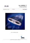
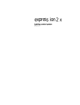
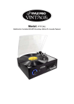
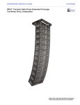
sE nsor
Touring Rack
USER MANUAL
Contents
Traveling panels ......................................... 3
Doors .......................................................... 3
Beacon ....................................................... 3
CEM ........................................................... 4
Removing the CEM .............................. 4
CEM swapping ..................................... 4
Dimmer modules ....................................... 5
Circuit breakers .................................... 5
Removing dimmer modules ................. 5
LEDs ..................................................... 5
Bump buttons ....................................... 5
Patch panel ................................................. 6
Feed, output and data connections ............ 6
Data ports ............................................. 6
Power distribution panel ....................... 7
Fuses .................................................... 7
Test points............................................ 7
Indicators .............................................. 7
Hot pockets .......................................... 7
Convenience outlets ............................. 7
Write-on strips ...................................... 7
Cooling fan ................................................. 8
Air filter ....................................................... 8
Ambient temperature ................................. 8
Electronic Theatre Controls, Inc.
UL and C UL Listed
AC Lighting Loads Only
For Indoor Use Only
Utilizer Dans Un Endroit A L'Abri
ETC Sensor dimming equipment is protected by
US patent number 5,352,958.
7053M1001
3030 Laura Lane, Middleton, WI 53562
800/688-4116 FAX 608/836-1736
Copyright 1994-95 Electronic Theatre Controls, Inc.
Specifications subject to change. Revised 1-95
2
Sensor Touring Rack User Manual
sE nsor
Touring Rack
USER MANUAL
➋
➊
➍
➌
Dimmer Outputs
The Sensor Touring Rack is a modular dimming system that consists of
a Control Electronics Module (CEM) and fan-cooled dimmer modules
housed in a steel frame with ABS plastic exterior paneling.
Note: The illustrations in this manual represent a typical rack. Many
racks are custom-built to customer specifications and so may not
match the illustrations.
➎
➐
➏
Hot Pockets
➑
➒
Traveling panels
The Sensor Touring Rack is protected during travel by front and back
traveling panels. These must be removed when the rack is being used.
The rack will not function while they are installed. To remove the
panels, follow these steps:
1. Insert a finger into each latch hole along the top edge of the front or
back of the rack.
2. Press latch bolt until it is fully retracted. It will click and stay in
retracted position.
3. Grasp the panel by the two handles. Lift panel until bottom edge is
free of the lip.
Caution: The panel is heavy. Do not drop it on your feet.
1. Control Electronics
Module (CEM)
2. Latch hole
3. Patch bay - light switch
4. Patch bay - outputs
5. Dimmer modules
6. Beacon
7. Patch cables
8. Patch bay - hot pockets
9. Spare dimmer modules
4. Pull bottom edge out slightly, then lower panel until it is free of the
rack.
To replace the panels, set the top edge, then lower the bottom edge
into place. Press the latch bolts to lock panel into place.
Doors
Each Sensor rack is equipped with a full-height door that contains an
electrostatic air filter to protect each column of dimmer modules. To
ensure proper cooling, the doors must be kept closed except when you
are working on the rack. The patch panel has a solid door with no filter.
This door may be left open while operating.
Beacon
An LED status beacon is mounted between the dimmer and patch
panel doors. Under normal operating conditions, this beacon is illuminated. If the rack’s CEM senses a problem with the rack, the beacon
flashes until the problem has been corrected.
If the beacon is flashing or off, check the CEM’s display for error
messages. See the CEM User Manual for more information or call ETC
Technical Services at 800/775-4382.
CEM
The Sensor Control Electronics Module (CEM) is the primary user interface for
the Sensor dimming system. It includes a keypad for user input, and an LCD
screen for information display. The CEM is located in the top slot of the
touring rack. The SP48 rack also provides a slot for a spare CEM.
For detailed information about the CEM, see the CEM User Manual.
sE nsor
Dimmer
7
8
9
Exit
OA
About
4
5
6
Next
OB
Backup
1
2
3
Thru
OC
Setup
A/B
0
At
Clear
Enter
ETCLink
Reset
Handle
Removing the CEM
In certain situations, you may need to remove the CEM. You do not need to
disconnect power to the rack prior to doing so.
To remove the CEM, slide the retractable handle out of the bottom edge of
the front panel, grasp it firmly, and pull the module out. Replace the handle. To
reinstall the module, align it correctly and press it firmly into place by the
sides.
Warning: The CEM contains exposed electrical components. Do not touch any
of the CEM’s internal components while removing the module. Do not touch
the bottom of the CEM until the module is completely removed. Two holes in
the CEM’s bottom panel expose live AC power. Use only the handle to pull out
the CEM.
CEM swapping
In multiple rack Sensor systems, each CEM contains complete system configuration information for the entire system. This allows you to swap CEMs in
the unlikely event that a CEM should fail.
Once you swap CEMs, use the new CEM to re-enter the ETCLink address of
the current rack. The CEM will then load the appropriate settings and tables
for that rack. For instructions on setting the ETCLink address, see Setting
ETCLink address in the CEM User Manual.
If your rack includes a spare CEM, you may load the settings for the rack into
both modules. This allows you to swap CEMs without needing to do any
additional programming. For more information, see Replacing a CEM in the
CEM User Manual.
4
Sensor Touring Rack User Manual
Dimmer modules
OFF
OFF
Each Sensor rack contains one active CEM. The SP48 also provides space for
a spare. Each rack also contains 12, 24, 36, or 48 dimmer modules. (If doubleheight modules are used, racks may be configured with fewer dimmer modules.) Sensor racks support 15A, 20A, 50A, or 100A dimmer modules in
various combinations. Racks with patch bays provide slots for three spare
dimmer modules.
➊
➋
Signal
20 A
Signal
20 A
Standard Sensor 20A dimmer module
1. Circuit breakers
On the left end of a dimmer module’s front panel are either one or two circuit
breakers. If the breaker switch is to the right, the circuit is off or tripped. If the
breaker switch is to the left, the circuit is on. In the event of a short circuit, the
circuit breaker trips automatically and the dimmer shuts off. Once the problem
causing the short circuit has been resolved, turn the circuit breaker back on,
and the dimmer will resume operation.
Removing dimmer modules
In certain situations, you may need to remove a dimmer module. Dimmer
modules are held in by the module retainer that extends over the left edge of
the modules. To remove the module, follow these steps:
Warning: Be careful not to trap your fingers between the module and the rack
when inserting or removing modules.
1. Turn circuit breakers off on the module to be removed.
2. Press module retainer in. Retainer is spring-loaded and retracts easily.
3. Grasp the metal handle that extends from the face panel.
4. Gently pull the dimmer module out.
To replace the module, push back the retainer and insert the module firmly
until you feel it seat securely. When the module is correctly seated, it should
be flush with the other dimmers in the rack.
Warning: When modules are removed, do not touch the exposed copper bars.
If more than one adjacent modules are removed, the high voltage copper bars
are easy to reach.
2. LEDs
All modules have an LED marked Signal which is on whenever the dimmer is
on. Sensor AF (Advanced Features) modules also have an LED marked Output
which is on whenever the dimmer’s output is above zero. If the module
contains two dimmers, it will have two sets of LEDs, one for each dimmer.
Bump buttons
Your rack may be equipped with optional bump buttons. The bump buttons
run down the strip to the right of the door protecting the dimmer modules.
Each dimmer has a corresponding bump button. Press the bump button to
raise that dimmer’s outputs to full.
Sensor Touring Rack User Manual
5
Dimmer Outputs
1
A B C D E F G H
I
J K L M N O P
2
3
4
5
6
7
8
9
10
11
12
13
14
15
16
17
18
19
20
21
22
23
24
25
26
27
28
29
30
31
32
33
34
35
36
37
38
39
40
41
42
43
44
45
46
47
48
Hot Pockets
1
2
3
4
Patch panel
The optional patch panel allows you to patch dimmer modules to output
circuits. Each multi-pin connector on the back of the rack leads to a cluster
of cables by the patch panel. In a rack with 12-circuit multi-pin connectors,
the cables are labeled A1 through A12, B1 through B12, and so forth. In a
rack with 6-circuit multi-pin connectors, they are labeled A1 through A6, B1
through B6, and so forth. The patch panel contains connectors, labeled 1
through 48 or 1 through 96, corresponding to the dimmer modules.
To connect an output circuit to a dimmer module, insert the appropriate
cable connector into the appropriate dimmer connector. The panel provides
either two or four outputs per patch point (two is standard).
The patch panel also contains patch connectors for the rack’s hot pockets.
Hot pockets connect outputs to the main power feed and are not dimmed.
You may connect an output directly to a hot pocket on the back of the rack,
or you may patch it to the hot pocket through the multi-pin connectors on
the patch panel.
Feed, output and data connections
The back side of the Sensor Touring Rack contains the stage pin and/or
multi-pin connector panels, the data ports and the power distribution panel.
Cables to your lights or other output devices are plugged into the connector
panels. White write-on strips beneath each row of connectors allow you to
label the connectors using a grease pencil. The power distribution panel
contains the main circuit breaker, Cam-Lok power input connectors, hot
pockets, and convenience outlets.
Note: Three types of connector panel (Pyle National, Socapex or Veam) are
available for the Sensor Touring Rack. You may exchange connector panels
as necessary. Contact ETC Technical Services for information on ordering
and installation.
Data ports
The control panel contains connectors for DMX512 A, DMX512 B and
ETCLink input and pass-through. Each port also has a terminator button. If
this rack is the last rack in the system, you must enable the terminators. To
enable the terminator, press the terminator button. When the button shows
a green indicator, the terminator is enabled.
DMX A
6
DMX B
ETCLink
Sensor Touring Rack User Manual
Power distribution panel
Attach the Cam-Lok power connectors in the following order:
1. Grounding connector (Green)
2. Neutral connector (White)
3. Phase connectors (Red/Blue/Black)
Disconnect connectors in reverse order.
Warning: Multiple power leads may be attached to this rack. Disconnect all
power leads before servicing or attempting to work on any part of this device.
Cam-Lok power connectors must be installed and removed by qualified
personnel only.
Convenience outlets
Main circuit breaker
➎
Hot pockets
MAIN
➏
400A.
➍
ØA
ØB
ØC
NEU
GND
Cam-Lok inputs
➊
➋
1. Fuses
➌
One 2AG fuse is located above each phase connector. The fuse protects
that phase’s indicator and test point.
2. Test points
One test point is located above each phase connector, the Neutral
connector and the Ground connector. The test points allow you to take
AC measurements.
Phase connector detail
3. Indicators
The indicator light located above each phase connector indicates whether
that phase has power.
4. Hot pockets
Hot pockets are power connectors connected directly to the main power
feed. They are not controlled by dimmers. Output circuits may be connected directly to a hot pocket, or may be patched to it through the multipin connectors and the patch panel.
5. Convenience outlets
Four 120 VAC convenience outlets are provided.
6. Write-on strips
Use a grease pencil to make notes on the write-on strips by the convenience outlets and hot pockets. Use a clean, dry cloth or paper towel to
clean them.
Sensor Touring Rack User Manual
7
Cooling fan
Each column of dimmer modules is cooled by a fan located at the bottom of
the rack. The fan(s) runs when any dimmer in the rack is receiving DMX512
control signal over zero. They continue to run for five minutes after all
dimmers are off.
Air filter
Each Sensor rack is equipped with an electrostatic air filter mounted in each
rack door. The rack’s cooling fan draws air through the filter, over the
surfaces of the modules and then blows it out the bottom of the rack. The
air filter removes dust and other airborne debris from the cooling air.
Cleaning the filter
To ensure proper cooling, the filter(s) should be cleaned every six months
(more often in dirty locations). With proper care and regular cleaning, the
filter should last as long as your Sensor rack. To clean air filter, follow these
steps:
1. Open the door.
2. Brush or vacuum filter from both sides.
3. If a more thorough cleaning is necessary, use compressed air to blow
out embedded dust and dirt.
To remove air filter (for replacement or more thorough cleaning) follow
these steps.
1. Open the door.
2. Use a Phillips-head screwdriver to remove the metal strip holding down
the left side of the filter.
3. Remove filter from door.
4. Reverse procedure to replace filter.
Ambient temperature
The average temperature in the space where the rack is located should be
about 68°F (20°C). Under no circumstances should the temperature exceed
104°F (40°C).
Note: The ambient temperature displayed by the CEM is only shown when
the fan is running. Use a thermostat or other external thermometer to
determine current room temperature
Warning: Never place objects that may block air flow beneath or in front of
your rack.
8
Sensor Touring Rack User Manual