1
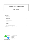
95
7 Introduction to op amps
−
Vin
Vout
+
(a)
100 k
−
Vin
10 k
+
−
+
Vout
1 MΩ
(b)
Fig. 7.6. (a) Op amp voltage follower; (b) voltage follower as the input stage to an
inverting-op-amp circuit.
You can reproduce this effect more simply by touching the probe tip
with your finger. 60 Hz noise is pervasive throughout North America
(50 Hz in Europe) and is often the dominant background noise in electronic equipment.
$ Try amplifying this low-power signal using the inverting-amplifier
circuit previously constructed. Sketch the output and record your
observations.
$ Now, instead of driving the amplifier directly, insert a voltage follower as
shown in Fig. 7.6(b). Record the follower output as well as the amplifier
output. If the amplifier output saturates, choose a smaller feedback resistor to reduce the gain of the inverting amp. Explain your observations.
7.2.5 Difference amplifier
Fig. 7.7 shows the 741 configured as a difference amplifier, with the output
voltage equal to the difference of the two input voltages. A difference amplifier is both an inverting amp and a noninverting amp. An inverting amp is
created if Vin+ is grounded, whereas a noninverting amp is created if Vin− is
grounded. If both inputs are connected to signals, the difference between
the two signals is amplified. This follows since, if these inverting and noninverting amplifiers have equal gains, the output is proportional to the difference of the inputs. The gains are matched provided that R1 /R2 = R3 /R4 .