1
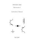
88
Hands-on electronics
R2
R1
Vin
~
I2
−
op amp
I1
+
Vout
Fig. 7.2. Op amp inverting-amplifier circuit. Note the negative feedback resulting from
the resistor that connects the output to the inverting input. Op amps are almost always
used with negative feedback.
We shall see next that these approximations lead to a very simple way
of analyzing op amp circuits.
7.1.3 Gain of inverting and noninverting amplifiers
Fig. 7.2 shows an op amp configured as an inverting amplifier. The
key principle at work in this circuit is negative feedback. The idea is
that a fraction of the output signal is applied at the inverting input.
Since the gain of the op amp is large and the noninverting input is grounded,
any nonzero voltage at the inverting input will cause a large output
voltage of the opposite sign. If you think about it, you will see that the
only stable situation that can result is that the voltage difference between
the inverting and noninverting inputs is zero. In other words, the op
amp will do whatever is necessary to zero the voltage difference at its
inputs.
Once this principle is grasped, it is easy to compute the gain of the op
amp inverting amplifier. Assuming the input currents of the op amp are
zero, all the current flowing in through R1 must flow out through R2 , i.e.
I2 = I1 . Assuming that the open-loop voltage gain (i.e. that without any
feedback) of the op amp is infinite, the voltage difference at the op amp’s
inputs must be zero. Applying Ohm’s law to R1 and R2 , and designating
the voltage at the inverting input as V− ,
V− = Vin − I1 R1 = 0
⇒ I1 = −
Vin
R1
(7.1)
(7.2)