1
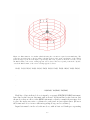
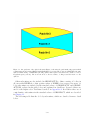
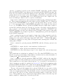
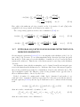
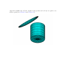
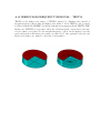
both sides of these elements, with a finite thickness to separate the two sides. The disadvantage of this approach is that, as a general rule, the size of the panels must be comparable
to the thickness, and thus a very large number of small panels may be required to achieve
accurate results. The second approach is to reduce the thickness to zero, and represent the
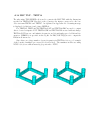
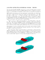
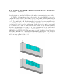
corresponding elements of the body by special ‘dipole panels’. This approach is analogous
to the thin-wing approximation in lifting-surface theory [21]. WAMIT permits the user
to specify a set of dipole panels, as described in Section 6.3. This option facilitates the
analysis of bodies with damper plates, strakes, and similar thin elements, without the need
to use very large numbers panels or to artificially increase the thickness.
6.1
THE GEOMETRIC DATA FILE
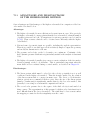
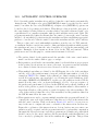
In the low-order method the wetted surface of a body is represented by an ensemble of
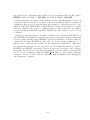
connected four-sided facets, or panels. The Geometric Data File contains a description
of this discretized surface, including the body length scale, gravity, symmetry indices, the
total number of panels specified, and for each panel the Cartesian coordinates x, y, z of
its four vertices. A panel degenerates to a triangle when the coordinates of two vertices
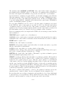
coincide. The order in which the panels are defined in the file is unimportant, but each
panel must be described completely by a set of 12 real numbers (three Cartesian coordinates
for each vertex) which are listed consecutively, with a line break between the last vertex of
each panel and the first vertex of the next. The value of gravity serves to define the units
of length, which apply to the body length scale, panel offsets, and to all related parameters
in the other input files. The coordinate system x, y, z in which the panels are defined is
referred to as the body coordinate system. The only restrictions on the body coordinate
system are that it is a right-handed Cartesian system and that the z−axis is vertical and
positive upward.
The name of the GDF file can be any legal filename accepted by the operating system,
with a maximum length of 16 ASCII characters, followed by the extension ‘.gdf’.
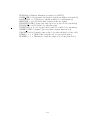
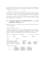
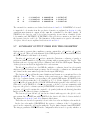
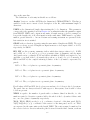
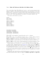
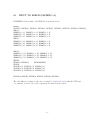
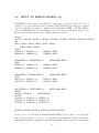
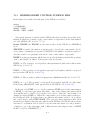
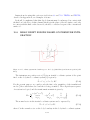
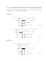
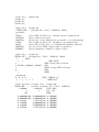
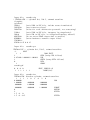
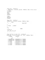
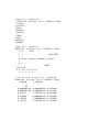
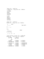
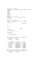
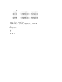
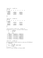
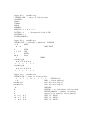
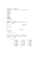
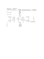
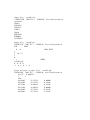
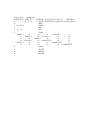
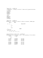
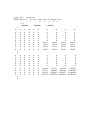
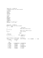
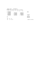
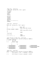
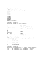
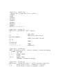
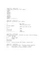
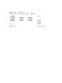
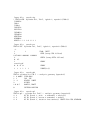
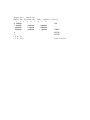
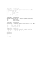
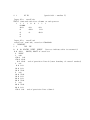
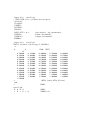
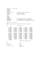
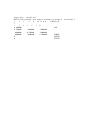
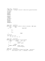
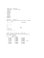
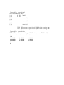
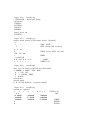
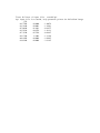
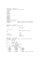
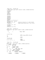
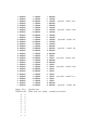
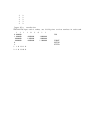
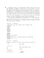
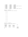
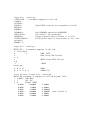
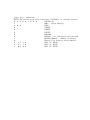
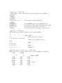
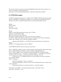
The data in the GDF file can be input in the following form:
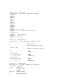
header
ULEN GRAV
ISX ISY
NPAN
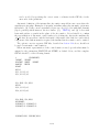
X1(1) Y1(1) Z1(1) X2(1) Y2(1) Z2(1) X3(1) Y3(1) Z3(1) X4(1) Y4(1) Z4(1)
6–2