1
A.24 MOTIONS OF A HINGED VESSEL – TEST24
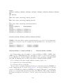
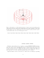
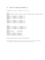
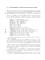
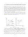
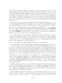
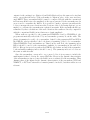
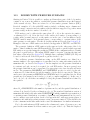
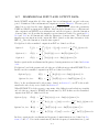
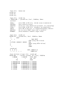
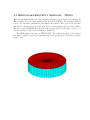
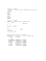
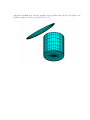
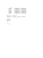
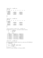
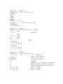
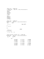
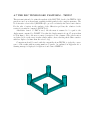
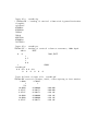
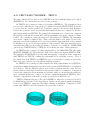
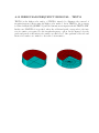
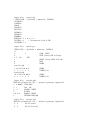
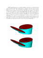
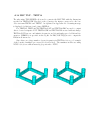
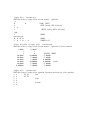
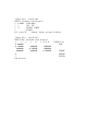
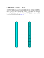
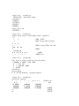
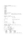
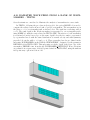
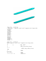
The subroutine CCYLHSP (IGDEF=-32) is used to generate a horizontal circular cylinder,
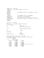
with spheroidal ends, as shown below. The dimensions are specified in TEST24.GDF. Two
planes of symmetry are specified. The cylinder is subdivided into five segments, to permit
the analysis of a vessel with transverse hinges between the segments. Half of the middle
segment and two others are in the domain x > 0. Four patches are required for these three
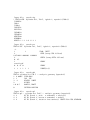
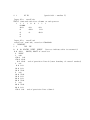
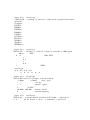
elements plus the spheroidal end. The total number of segments, specified in TEST24.GDF,
is used to read the x-coordinates of the boundaries between adjacent segments and also the
end of the vessel. The total number of segments is equal to seven, including five cylinders
plus two spheroids. Only the boundaries with coordinates x>0 are included in the last line
of the GDF file, since ISX=1.
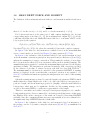
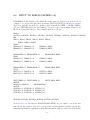
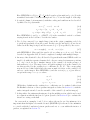
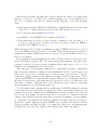
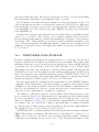
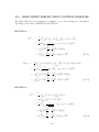
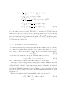
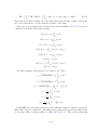
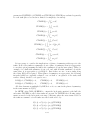
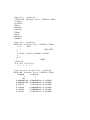
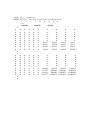
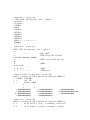
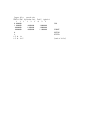
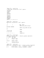
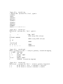
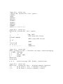
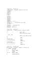
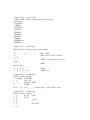
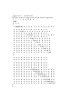
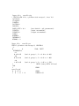
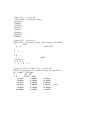
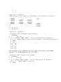
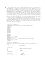
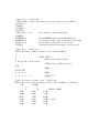
The generalized modes which represent the deflection of the hinges are defined in the
subroutine HINGE MODES in the DLL file NEWMODES.F, designated by the parameter
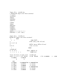
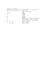
IGENMDS=22 in TEST24.CFG. This subroutine reads the appropriate input data from
the file test24 xhinge.dat, as described in Section 9.3. This input file specifies the symmetry
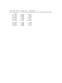
index ISX=1, number of segments, and the x-coordinates of the hinges. The last cylinder
and the spheroidal end are considered to be rigidly joined. Thus there are five ‘active’
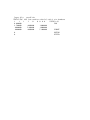
segments corresponding to the parameter NSEG in the file, and NEWMDS=4 is assigned
in the TEST24.POT file.
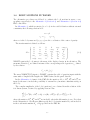
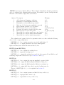
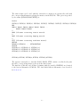
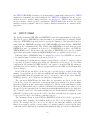
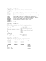
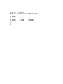
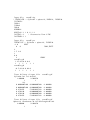
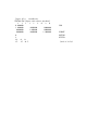
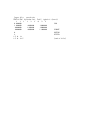
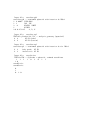
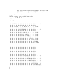
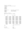
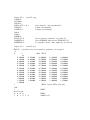
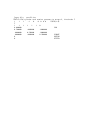
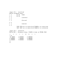
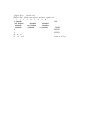
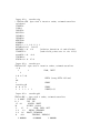
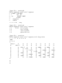
In the TEST24.FRC file, the 10×10 matrix of inertia coefficients is specified. No
external damping or stiffness matrices are input, corresponding to the situation where the
hinges are ideal without friction or other mechanical constraints.
Further information can be found in the headers and comments of the subroutines
which are used to generate the geometry and to represent the hinge modes.
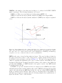
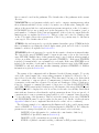
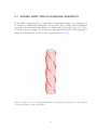
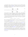
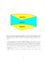
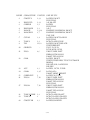
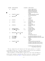
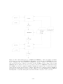
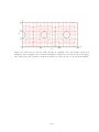
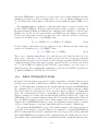
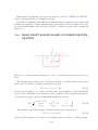
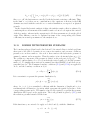
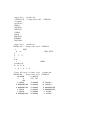
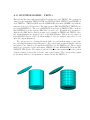
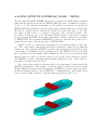
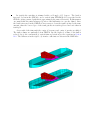
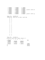
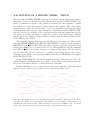
Figure A.2: Generalized modes used for the hinged barge with four hinges. The modes on the left are
‘tent functions’, suitable for use when ISX=0. When ISX=1 each mode must be either symmetric or
antisymmetric, as shown in the right column. The latter modes are used for TEST24. The conventional
rigid-body modes in heave and pitch represent the nonzero vertical motions at the two ends.