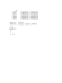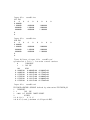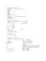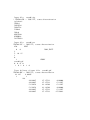
1
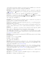
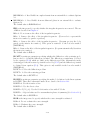
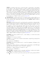
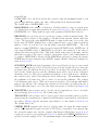
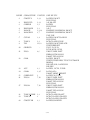
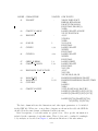
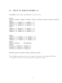
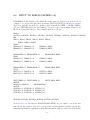
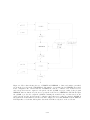
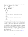
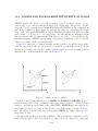
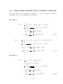
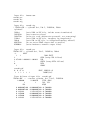
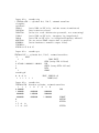
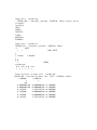
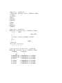
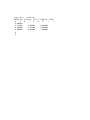
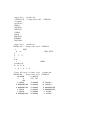
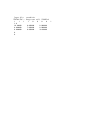
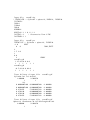
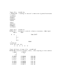
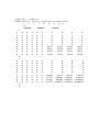
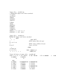
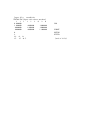
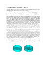
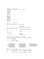
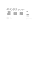
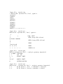
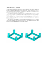
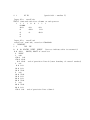
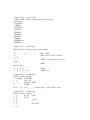
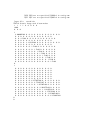
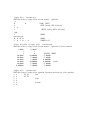
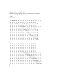
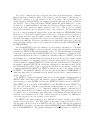
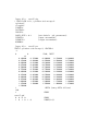
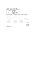
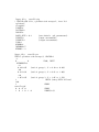
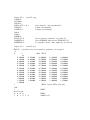
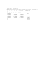
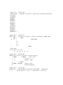
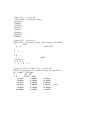
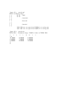
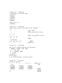
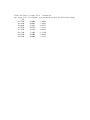
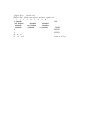
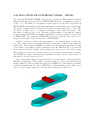
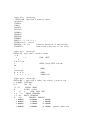
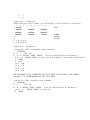
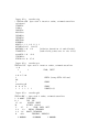
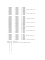
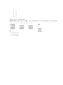
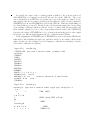
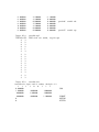
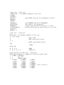
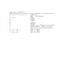
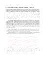
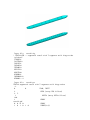
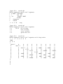
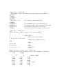
in Figure 6.1. The precise format of each coordinate is unimportant, as long as there
is at least one blank space between coordinates, and the coordinates of the four vertices
representing a panel are listed sequentially.
There are two situations when panels lie on the free surface, and thus all four vertices
are on the free surface: (1) the discretization of a structure which has zero draft over
part or all of its submerged surface, and (2) the discretization of the interior free surface
for the irregular frequency removal as described in Chapter 10. For the first case, where
the panels are part of the physical surface, the panel vertices must be numbered in the
counter-clockwise direction when the panel is viewed from the fluid domain as in the case
of submerged panels. For the second case, where the panel is interior to the body and
non physical, the vertices must be numbered in the clockwise direction when the panel is
viewed from inside the structure (or in the counter-clockwise direction when the panel is
viewed from above the free surface). Details of the discretization of the interior free surface
are provided in Chapter 10.
Although the panels on the free surface are legitimate in these two special cases, a
warning message is displayed by WAMIT when it detects panels with zero draft, which
have four vertices on the free surface. This is to provide a warning to users for a possible
error in the discretization other than the above two exceptional cases. The run continues
in this case, without interruption. An error message is displayed with an interruption of
the run when the panels have only three vertices on the free surface, unless two adjacent
vertices are coincident. (The latter provision permits the analysis of a triangular panel
with one side in the free surface.)
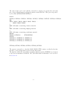
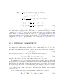
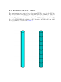
The three Cartesian coordinates of four vertices must always be input for each panel, in
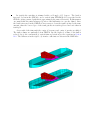
a sequence of twelve real numbers. Triangles are represented by allowing the coordinates
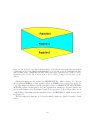
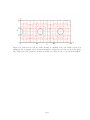
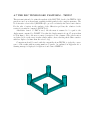
of two adjacent vertices to coincide, as in the center bottom panels shown in Figure 6.1.
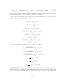
Two adjacent vertices are defined to be coincident if their included side has a length less
than ULEN × 10−6 . An error return results if the computed area of any panel is less than
ULEN2 × 10−10 .
The input vertices of a panel do not need to be co-planar. WAMIT internally defines
planar panels that are a best fit to four vertices not lying on a plane. However it is advisable
to discretize the body so that the input vertices defining each panel lie close to a plane,
in order to achieve good accuracy in the computed velocity potentials. An error message
is printed if a panel has two intersecting sides. A warning message is printed if a panel is
‘convex’ (the included angle between two adjacent sides exceeds 180 degrees).
The origin of the body coordinate system may be on, above or below the free surface.
The vertical distance of the origin from the free surface is specified in the Potential Control
File. The same body-system is also used to define the forces, moments, and body motions.
(See Chapter 5 regarding the change in reference of phase relations when walls are present.)
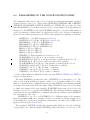
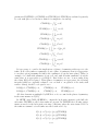
Only the wetted surface of the body should be paneled, and then only half or a quarter
of it if there exist one or two planes of symmetry respectively. This also applies to bodies
mounted on the sea bottom or on one or two vertical walls. The number of panels NPAN
refers to the number used to discretize a quarter, half or the whole body wetted surface if
two, one or no planes of symmetry are present respectively.
6–5