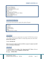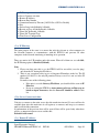
1
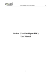
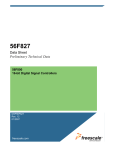
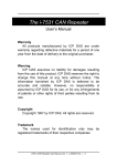
USER MANUAL
ETHERNET IO UNIT - Model ETH IO 2.0
Sparr Electronics Ltd.
No. 43, YMS Complex, HMT Main Road, Mathikere,
Bangalore - 560054, INDIA.
Phone: +91-80-23602836, +91-80-23606308
Fax: +91-80-23608346
E-mail: [email protected]
Web: http://www.sparrl.com
ETHERNET I/O UNIT ETH IO 2.0
CONTENTS
1. Introduction……………………………………………………………………………………………………….3
1.1. About Ethernet IO unit (ETH IO) – Overview ………………………………………….3
2. Features …………………………………………………………………..………………………………………..3
3. Application …………………………………………………………………………………………………………4
4. ETH IO 2.0- product contains……………………………………………………………………………….4
5. Board Specification……………………………………………………………………………………………..4
5.1. Indicators (LED’s)……………………………………………………………………………………..7
6. Connection and Configuration…………………………………………………………………………….8
6. 1. Connections……………………………………………………………………………………………8
6. 2. Programming through Web browser……………………………………………………11
6. 3. Programming through Telnet…………………………………………….…………………13
6. 4. Programming through Hyper Terminal………………………..………………………14
6.4.1. A. Network Configuration………………………………………………………..16
6.4.1. B. Serial Configuration RS232.…………………………………..................17
6.4.1. C. Server Configuration ………………………………………......................18
6.4.1. D. Load Factory Default.……………………………………….....................22
6.4.1. E. Change Configuration Password………………………………………….22
6.4.1. F. Save and Exit………………………………………………………………………..22
6.4.1. G. Exit………………………………………………………………………………………22
6.4.1. H. To upload New Firmware…………………………………………………….23
6.4.1. I. Enable Boot Message…………………………………………………………….23
6.4.1. J. Slave Configuration…………………………………………......................23
6.4.1. K. Serial Configuration RS 485………………………………………………….25
7. Factory Default Values...………………………………………………………….............................27
8. Troubleshooting ………………………………………………………………………………………………….28
9. Contact and Support…………………………………………………………………………………………….29
Figure1……………………………………………………………………………….......5
Figure2……………………………………………………………………………………..6
Figure3……………………………………………………………………………………..6
Figure4…………………………………………………………………………………..12
Figure5…………………………………………………………………………………..12
Figure6…………………………………………………………………………………..13
Figure7…………………………………………………………………………………..14
Figure8…………………………………………………………………………………..15
.
Sparr Electronics Limited
SEL/MKTG/Manual/ETH IO 2.0
REV:01
05/11/2014
Page 2
ETHERNET I/O UNIT ETH IO 2.0
1 Introduction
1.1 About ETH IO- 2.0 – Overview:
The ETH IO unit facilitates continuous monitoring of the Analog Inputs, Digital Inputs,
Status of Relays and also the parameters of the Slave units connected using RS 485
Interface to it using MODBUS protocol.
Each ETH IO unit supports up to 8 Analog Inputs, 8 Digital Inputs, 8 Potential free Relay
contacts, a query based response unit on the RS232 bus and a RS485 port to connect to a
maximum number of 6 slave units.
All the information about the status of various Inputs and the condition of the different
units connected to it from different interfaces will be sent to the centralized Server using
the RJ45 LAN interface.
2 Features
•
One RS 232 Serial interface is for establishing connectivity with the unit to be
monitored and is also used for configuring the unit.
•
One RS 485 Serial interface is for connecting to one or more RS 485 devices
using MODBUS protocol.
•
One RJ45 connector, for LAN network interface, used for communicating with
the server and also for the configuration of the unit through Telnet or by using
web browser.
•
Supports 8 digital inputs (ex. - closing and opening of doors, alarm conditions
etc.) for monitoring their status. With voltage range 0-24 V DC.
•
Supports 8 analog inputs (ex. – temperature monitoring, pressure monitoring etc.)
for monitoring their status.
•
Supports 8 relay outputs (ex. – switching of supply etc.) for controlling of various
devices connected to it.
•
Works with 12 V DC 1 Amp Power supply.
•
Capability to update the time from a Time Server.
Sparr Electronics Limited
SEL/MKTG/Manual/ETH IO 2.0
REV:01
05/11/2014
Page 3
ETHERNET I/O UNIT ETH IO 2.0
•
Capability to configure different types of RS 485 slaves units for data gathering.
3 Applications
Some of the applications where ETH IO could be used are
Remote ATM Management
Remote Mobile Tower Management
Remote Equipment Management
Building Management Systems – BMS
Remote Data Logging
Industrial Control etc
4 ETH IO-2.0 Product Contains
The unit when shipped has the following contents
1. Ethernet IO unit model ETH IO-2.0
2. Power Adaptor and
3. User Guide
5 Hardware Components
The Hardware component of ETH IO 2.0 unit is shown in the diagram as well as
described in the table below:
Sparr Electronics Limited
SEL/MKTG/Manual/ETH IO 2.0
REV:01
05/11/2014
Page 4
ETHERNET I/O UNIT ETH IO 2.0
Figure.1: Top view of the unit
Sparr Electronics Limited
SEL/MKTG/Manual/ETH IO 2.0
REV:01
05/11/2014
Page 5
ETHERNET I/O UNIT ETH IO 2.0
RS 485
8 Digital Inputs
Figure2: Digital Input side view
8 Analog Inputs
RJ45
LAN
RS232
Serial I/F
Figure3: Analog input side view.
Sparr Electronics Limited
SEL/MKTG/Manual/ETH IO 2.0
REV:01
05/11/2014
Page 6
ETHERNET I/O UNIT ETH IO 2.0
Interface
Description
RS-232 Serial 9 pin RS 232 Serial interface, used for serial communication as well as for
the configuration of the Ethernet IO unit. Supports maximum speed of
interface
115200 bps with various data parameters.
RS-485 Serial Serial interface for establishing the connection with other units over
MODBUS protocol. Supports maximum speed of 115200 bps with various
interface
data parameters.
10 Base-T or 100 Base-TX RJ45 Ethernet port which supports up to 100
RJ-45
Mbps speed for connection to Local Area Network (LAN) through Hub or
interface
Switch.
It is also used for communicating with the Server and also for the
configuring of the ETH IO 2.0 unit using Telnet or by web browser.
12 V DC, 1 Amp power with fuse and reverse polarity protection. Use the
Power
power adapter provided along with the unit or supply power from know
good source.
Power ON Red LED glows when power is supplied to the Ethernet IO unit.
Inputs
Digital
Analog
Pin No. 1 & 11 are Vcc(+5V Pin No. 1 is Vcc(+5V DC) and pin No. 10
DC) and pin No. 10 and 20 is for GND connection
are GND.
No. of inputs
8
No. of inputs 8
Input voltage
0-24V
DC
Relay outputs No. of outputs
Relay contacts
Relay contact rating
Input
Voltage
8
0-12 V for input pin 1-7. 0100 V for input pin 8 only.
Normally Open, Normally Close and
Common
1A at 230V AC or 2A at 24V DC
5.1. Indicators (LED’s):
Ethernet IO unit has many LED’s indications to indicate the status of power, device
connectivity, Inputs (Digital) and Outputs (Relays).
The following table gives a brief explanation of these LED’s.
Sparr Electronics Limited
SEL/MKTG/Manual/ETH IO 2.0
REV:01
05/11/2014
Page 7
ETHERNET I/O UNIT ETH IO 2.0
LED
Power
indication
Color
RED
Device
ready
status
YELLOW
Digital
inputs
RED
Relay
Outputs
RED
Function
The Red LED glows when 12V DC Power supply is plugged
in to the power socket and remains ON till the Power is
available to the unit.
When the power is “ON” and LAN is not connected, it will
blink for 12.5 seconds and waits for “Enter” Character from
serial port for getting in to Configuration mode.
After 12.5 second it will stop blinking and glow.
Red and Yellow both LED’s glowing status shows that the
ETH IO-2.0 is ready to use.
Glowing indicated that “HIGH” condition is applied to the
corresponding digital input.
Not glowing indicated that “LOW” condition is applied to the
corresponding digital input.
LED’s of respective Relays glows when the common relay is
switched from NC to NO
6 Connection and Configuration
6.1. Connections:
Proper connection for different devices should be made for the desired functioning of the
unit.
• RS232 Connection: This port should be connected for Computer for Initial
Configuration of the unit and later could be connected to the Device or
Equipment which needs to be monitored.
• RS485 Connection: The 1st pin is TRx+ and 2nd pin is TRx- and these two should
be connected to the TRx+ and TRx- outputs of the RS 485 device to be
monitored accordingly. You can connect up to a maximum of 6 devices
supporting RS 485 with MODBUS Protocol.
• RJ45 LAN connection: Connect the RJ 45 Jack using appropriate cable to either
a computer or to Switch / Hub port of your Local Area Network. This interface is
used for both configuration of the using Web Browser or using Telnet from a
computer connected to your LAN.
Sparr Electronics Limited
SEL/MKTG/Manual/ETH IO 2.0
REV:01
05/11/2014
Page 8
ETHERNET I/O UNIT ETH IO 2.0
•
Digital and Analog Input connections: The ETH IO has capability to monitor
various parameters based on the Inputs provided to the unit. Please ensure that the
inputs are connected as per the pin out details provided below;
Input
Digital
Analog
•
Pin description
Pin No. 1 & 11 – Vcc (5 V DC), Pin no. 10 & 20 – Ground. [these Vcc
and GND are for tri state contacts]
Input 1 – pin no. 2 (+ve) & 3 (-ve).
Input 2 – pin no. 4 (+ve) & 5 (-ve).
Input 3 – pin no. 6 (+ve) & 7 (-ve).
Input 4 – pin no. 8 (+ve) & 9 (-ve).
Input 5 – pin no. 12 (+ve) & 13 (-ve). Input 6 – pin no. 14 (+ve) & 15 (ve).
Input 7 – pin no. 16 (+ve) & 17 (-ve). Input 8 – pin no. 18 (+ve) & 19 (ve).
Pin no. 1 – Vcc (5 V DC), Pin no. 10 – Ground
Pin no. 2 – Input 1. Pin no. 3 – Input 2. Pin no. 4 – Input 3.
Pin no. 5 – Input 4. Pin no. 6 – Input 5. Pin no. 7 – Input 6.
Pin no. 8 – Input 7. Pin no. 9 – Input 8.
Relay outputs: The unit has 8 Relay outputs each with 3 output points Common, Normally Open (NO) & Normally Closed (NC) totaling to 24 pins.
Relay 1: pin no. 1 – NO, pin no. 2 – NC and pin no. 3 – Common.
Relay 2: pin no. 4 – NO, pin no. 5 – NC and pin no. 6 – Common.
Relay 3: pin no. 7 – NO, pin no. 8 – NC and pin no. 9 – Common.
Relay 4: pin no. 10 – NO, pin no. 11 – NC and pin no. 12 – Common.
Relay 5: pin no. 13 – NO, pin no. 14 – NC and pin no. 15 – Common.
Relay 6: pin no. 16 – NO, pin no. 17 – NC and pin no. 18 – Common.
Relay 7: pin no. 19 – NO, pin no. 20 – NC and pin no. 21 – Common.
Relay 8: pin no. 22 – NO, pin no. 23 – NC and pin no. 24 – Common.
Http Post format for Relays:
Status of the relays will be changed through HTTP post. There are two formats of
posting HTTP post through any medium, for relays. 8 Relay Status are also stored
in flash to reflect on next Power ON. By Loading default all Relay status can be
reset to 0.
Sparr Electronics Limited
SEL/MKTG/Manual/ETH IO 2.0
REV:01
05/11/2014
Page 9
ETHERNET I/O UNIT ETH IO 2.0
To switch ON or OFF the relay using HTTP Poster, command is as follows.
URL: is http://<IP Address of ETH I/O>/relay.html
Content of the body is:
Relay:
$11111111% - 8 bit data represents ON or OFF status of the relay.1 For ON
$END%
and 0 For OFF.LSB presents 8th relay and MSB presents 1st relay.
Click on the POST button.
Example: to switch ON all relays, http command is as shown below.
IF the poster is not there in your browser. It can be added from the settings,
Extensions and Get more extensions option. Select Chrome poster, which will be
added to right side of browser’s tool bar
To set the events:
1. $Relay#ON or OFF#T HH:mm:SS%
URL: is http://<IP Address of ETH I/O>/event.html
Content of the body is:
Event:
$4#ON#T 15:34:00% - 4 is the number of relay. it can be 1 to 8, ON for ON
$END%
switching relay and OFF for switching OFF relay. Time
in 23 hours format.
This command will switch ON the relay at 15:34:00 Hours.
Sparr Electronics Limited
SEL/MKTG/Manual/ETH IO 2.0
REV:01
05/11/2014
Page 10
ETHERNET I/O UNIT ETH IO 2.0
2. $Relay#ON/OFF#T HH:mm:SS#T HH:mm:SS%/r/n
Example:
URL: is http://<IP Address of ETH I/O>/event.html
Content of the body is:
Event:
$4#ON#T 15:34:00#T 14:15:00% - 4 is the number of relay. it can be 1 to 8, ON
ON $END%
for switching relay and OFF for switching OFF
relay. Time in 23 hours format.
This command will switch ON the 4th relay at 15:34:00 Hours and 14:15:00.
NOTE:
o Maximum bytes for single post: 300 bytes
o Maximum length of a single line: 100.
o Number of string for one event (Either ON or OFF in a single relay):
10.
o If 10 strings have been used for the single event and one wants to
write more strings then the default value should be loaded to the unit.
This will empty the flash where relay status is saved.
o If the maximum length limit or maximum byte limit or both are
crossed then the unit will not accept that command and it will show an
error message.
o TO GET THE CONFIGURED EVENTS:
Give a get command to RTU thorough HTTP:
GET<space>/event.html<space>
In the similar way these relay status can also be controlled by the status of the
digital and analog inputs.
Therefore, according to the digital and analog inputs the status of the relay will
change. To configure this, Http post has to have the following pattern:
$Relay#ON/OFF#T HH:mm:SS#Dn H/L#An G/LCOUNT%
Example:
$8#OFF#T 10:10:10#D1 H#A8 G2000%
$7#ON#T 10:10:10#D3 L#A3 L100%
Here: H – for high digital input.
L- for low digital input.
G- Greater than the analog input count.
L- Lower than the analog input count.
Sparr Electronics Limited
SEL/MKTG/Manual/ETH IO 2.0
REV:01
05/11/2014
Page 11
ETHERNET I/O UNIT ETH IO 2.0
Note: Count in the analog input will be according to the voltage applied to the
input. Maximum count is 4095, and it will be for the maximum allowed
voltage to that pin.
This 4095 will be distributed in the allowed voltage range. So for pin number
8 input 100 V will be for count 4095 and in other pins it will be for 12 V.
•
Once you are through with connecting all the required devices, connect the power
to the unit using the 12V DC power adaptor supplied along with the unit to the
Power Jack. Do ensure that the Power ON indicator become RED indicating
proper Power.
•
If you are planning to configure the unit using computer connected to the LAN,
you may proceed as per details provided in point 6.1.
• If you are planning to configure the unit using Serial interface then remove the
LAN connection and connect the RS232 serial port to a computer running a
terminal emulation program before powering on the unit.
To configure the device for monitoring (digital inputs, analog inputs, RS232 side, RS 485
side) and controlling (Relay status), the following methods can be used.
•
•
•
Through Web browser.
Through Telnet.
Through Hyper terminal.
6.2. Programming through Web browser:
In order to program ETH IO 2.0 using web browser, open a new web browser window in
your computer from program like Internet Explorer, Mozilla Firefox, and Google Chrome
etc. Enter ‘http://192.168.0.154” or the correct IP Address of the unit in the browser
address field and press the ‘Enter’ key. Enter the Password when prompted. Default
password is 77277. Change the parameters of the unit like IP Number, Subnet Mask, and
Gateway etc to meet the requirements of your Network as per your requirement.
Please note that only Network Configuration of the unit can be programmed using
the web browser.
For example: If the IP Number of the ETH IO 2.0 is 192.168.0.254 then you have to enter
http://192.168.0.254 in the web browser address field and press ‘Enter’ Key.
Sparr Electronics Limited
SEL/MKTG/Manual/ETH IO 2.0
REV:01
05/11/2014
Page 12
ETHERNET I/O UNIT ETH IO 2.0
Please ensure that your computer is having the IP number in the same range as that
of ETH IO or else change the same.
After changing the parameter value in any of the browsed page, you need to click on
‘Update’ button in the same page and ensure to press ‘Save & Reboot’ button. You can
also set the unit to its default values by clicking on ‘Load default’ from any page and then
click on save & Reboot.
Figure4: ETH IO LOG-IN page in browser
Default login password is 77277. When you login it will display MAC Address,
Firmware version, and Product Model and Boot loader details of the unit.
Figure5: ETH IO Home page in browser
Sparr Electronics Limited
SEL/MKTG/Manual/ETH IO 2.0
REV:01
05/11/2014
Page 13
ETHERNET I/O UNIT ETH IO 2.0
User can proceed to configure the unit by clicking on CONFIGURE or Next option in the
home page. Using this page you can configure IP address, subnet mask, gateway,
Network Interface and DHCP. All these parameters are explained in detail later in the
manual.
Figure6: ETH IO Configure page in browser
To configure other parameters one has to use either Serial RS232 port using
terminal programs like Hyper terminal or using TELNET connection from any
computer connected to the LAN.
6.3. Programming through Telnet:
Before configuring the unit, ensure that ETH IO is connected to the LAN & configured
properly by performing the Ping test from the command prompt of your computer.
C>Ping<space><IP address><space><-t>
If you are receiving proper ping response, then the unit IP is properly set and responding.
You may proceed to configure the unit. If you do not receive proper ping response either
the IP provided for pinging is different from the IP configured or the LAN cable is not
inserted properly to the unit.
Sparr Electronics Limited
SEL/MKTG/Manual/ETH IO 2.0
REV:01
05/11/2014
Page 14
ETHERNET I/O UNIT ETH IO 2.0
ETH IO-2.0 can also be programmed through Telnet program available in Windows.
Open the Telnet program by typing Telnet in Start Run Open and select ‘Connect as
Remote System’ from the Connect menu.
Enter the correct IP Address and the Port number of the ETH IO unit e.g. 192.168.0.254.
The reserved Port number in ETH IO for configuration of the unit through Telnet is 7353.
Click on ‘Connect’ and enter the Password when prompted. Default password is 77277.
Figure7: Connect through Telnet
You can directly enter the following command in run window: Telnet<space><IP
address><space><7353>
Change the parameters as per your choice. For detailed description on parameters of ETH
IO, see later section.
The telnet command and options screen will look same under Windows 2000 and
XP where one will use > open 192.168.0.254 7353 after issuing Telnet command in
the Run. You can also use programs like Hyper Terminal or Putty if the operating
system does not support Telnet or enabled.
6.4. Configuration through Hyper Terminal:
1). Use any Communication Program like Hyper Terminal, XTalk, and Mirror etc to
configure ETH IO-2 through RS 232 Serial Interface. The Serial port settings should be
set to 9600 bps, 8 data bits, No Parity, 1 Stop bit with Flow control option selected as
none. Select appropriate Communication (COM) port through which the ETH IO is
connected.
2) For entering the Configuration Mode, remove the RJ45 LAN Jack, if connected, and
power ON the unit. The following Message in the Hyper Terminal will be displayed
“Network Error, Press Enter for Configuration...Waiting 12.5 Sec....
Sparr Electronics Limited
SEL/MKTG/Manual/ETH IO 2.0
REV:01
05/11/2014
Page 15
ETHERNET I/O UNIT ETH IO 2.0
Press Enter Key to proceed with the Configuration.
Figure8: RS 232 serial interface port.
3). Once the ETH IO senses the Enter key, it will send the following string, which will
appear on Screen:
Enter configuration password:
Enter the default Password, which is 77277.
(If the password entered is wrong, then the ETH IO will prompt you to re-enter Correct
Password for three times. If all the three attempts fail then you will have to follow step 2
in getting the option to enter a password again. If you are still not successful, please do
call us for resetting of Password with Master Password from Factory).
4) After entering the correct password a window having following option will appear on
the hyper terminal.
Enter the choice, for example ‘a’ for entering the Network configuration mode, and
configure the ETH IO. Note that the Options / Choices are Case Sensitive. Refer the
last Section of this manual for various factory default values options and the
functionality.
Network Error, Press Enter for Configuration...Waiting 12.5 Sec....
Entering Configuration Mode
Enter Configuration Password: *****
Sparr ETH I/O 2.0 Configuration F/W Version 1.01 3271
MAC Address: 00-17-85-0A-00-01
a>.Network Configuration
Sparr Electronics Limited
SEL/MKTG/Manual/ETH IO 2.0
REV:01
05/11/2014
Page 16
ETHERNET I/O UNIT ETH IO 2.0
b>.Serial Configuration RS232
c>.Server Configuration
d>.Load Factory Defaults
e>.Change Configuration Password
f>.Save and Exit
g>.Exit
h>.To Upload New Firmware
i>.Enable Boot Messages 0=Disable 1=Enable
j>.Slave Configuration
k>.Serial Configuration RS485
Enter Selection:|
(A). Network Configuration:
If ‘a’ has been selected from above options, these options will appear:
a>.IP Address
b>.Netmask
c>.Gateway
d>.DNS IP Address
e>.Network Interface
f>.Exit
g>.DHCP 0=Disable 1=Enable
(A.a). IP Address:
The IP address must be set to a unique value in the network. The ETH IO will not connect
to the network if the assigned IP address is already being used by some other device.
Default is 192.168.0.254.
Example:-192.168.0.250
Please do set the IP number to 0.0.0.0, for ETH IO to acquire IP number from DHCP
Server in the Network automatically.
(A.b). Netmask:
A netmask defines the number of bits taken from the IP address that are
assigned for the host section. Default is 255.255.255.0
Example: - 255.255.255.0
Sparr Electronics Limited
SEL/MKTG/Manual/ETH IO 2.0
REV:01
05/11/2014
Page 17
ETHERNET I/O UNIT ETH IO 2.0
(A.c). Gateway:
The Gateway or Router allows communication to other LAN segments. The gateway
address should be the IP address of the router connected to the same LAN segment. The
gateway address must be within the local network address range. There is no default
value.
Example: - 192.168.0.XXX
Note: Gateway has to be configured to get faster response and no delay in http post
commands.
(A.d) Network Interface:
Provided option for choice of the Network operating speed
DEFAULT it is 100mbps.
(A.e). EXIT:
Use this option to exit and come back to the previous selection menu.
(A.f). DHCP:
If this option is enabled and a DHCP server exists on the network, it will provide the unit
with an IP address, gateway address, and subnet mask when the unit boots up.
Default setting is ‘Disable’.
(B) Serial Configuration RS232:
After selecting ‘b’ in serial configuration RS232, configuration will be opened with these
parameters:
a>.Baud Rate
b>.Data Parameters
c>.Flow Control
d>.Character Wait Timeout [00 - 254 msec]
e>.Exit
(B.a). Baud rate:
The speed or baud rate selected for the unit should match with the Serial port of the
device connected for proper Serial data transfer. Set the correct baud rate with option “a”
Sparr Electronics Limited
SEL/MKTG/Manual/ETH IO 2.0
REV:01
05/11/2014
Page 18
ETHERNET I/O UNIT ETH IO 2.0
to “j” for valid baud rates of 300,600,1200, 2400(Default), 4800, 9600,
19200,38400,57600 and 115200 bps.
(B.b). Data Parameter:
There are Ten options available for Data parameter settings with choices from “a” to “j”
for various Data bits, Parity and Stop bit selections.
(a) N (No Parity), 8( Data bit), 1(Stop bit) (default)
(b) E (Even Parity), 7(Data bit), 1(Stop bit)
(c) O (Odd Parity), 7 (Data Bits), 1(Stop Bit)
(d) E (Even Parity), 8(Data bit), 1(Stop bit)
(e) O (Odd Parity), 8(Data bit), 1(Stop bit
(f) N (No Parity), 8( Data bit), 2 (Stop bit)
(g) E (Even Parity), 7(Data bit), 2(Stop bits)
(h) O (Odd Parity), 7(Data bit), 2(Stop bits)
(i) M (Mark Parity), 8(Data bit), 1(Stop bit) and
(j) S (Space Parity), 8(Data bit), 1(Stop bit).
(B.c). Flow Control:
Flow control will be essential for handshaking with the Serial device, for stopping serial
data input/output to avoid character loss. Supported options are NONE for No Flow
control, XON/XOFF for Software Flow control and RTS/CTS for Hardware Flow
control.
Default None.
It is highly recommended to use Flow control for higher Serial speed applications.
(B.d). Character Wait Timeout:
Character wait time out defines how long the ETH IO should wait before sending
accumulated serial characters to network. Serial data arrives at ETH IO, which is
packetized and sent through the LAN after this period. Set this to smaller value for
immediate transfer.
Default is 0 Milliseconds. You can set this up to 254 milliseconds.
(C). Server Configuration:
After configuring ‘a’ and ‘b’ options, you may proceed with configuring Server
Configuration.
Sparr Electronics Limited
SEL/MKTG/Manual/ETH IO 2.0
REV:01
05/11/2014
Page 19
ETHERNET I/O UNIT ETH IO 2.0
a>.IP Filtering
b>.Server Connect wait time
c>.Remote IP Address
d>.Remote Port Number
e>.Connection Inactivity Timeout [1-65534 Sec, 65535 to Disable]
f>.Exit
g>.Defeat Long Ack 0=Disable 1=Enable
h>.Restart on Loss of Link 0=Disable 1=Enable
i>.Telnet IAC 0=Disable 1=Enable
j>.Telnet IAC Terminal Type
k>.Time Server Configuration
(C.a). IP Filtering:
The main purpose of the same is to ensure that only the relevant or select computers in
the Network connects or communicates with the ETH IO and prevents all other
computers in the Network interfering or intruding in its operation.
There are entries for 5 IP numbers under this menu. When all of them are set to 0.0.0.0,
the IP Filtering option is Disabled (Default).
Note:
1. Please note that once this is set, the ETH IO will be accessible (even for ping)
only from the PC having this IP address.
2. There is one exception to this in case of forgotten IP numbers in the list. The IP
number 192.168.0.1 is the only IP permitted always even if it is not set in the IP
Filter table.
Do make a note of the following points:
• If the unit is set with Gateway IP address, you should add the same in IP
Filter list.
• If you are setting the ETH IO to Auto connect to Server on Power-up or
based on input characters, then the Server IP should be added to this
list.
(C.b). Server Connect wait time:
Unit tries to connect to the main server after this much time interval. If server will not be
available then after this much time it will again try to connect, and keep try to connect
until it will find the connection.
No information of the previous data will be posted; Data will be posted only when there
will be a connection between server and the unit.
Default it is 60 second.
(C.c). Remote IP address:
Sparr Electronics Limited
SEL/MKTG/Manual/ETH IO 2.0
REV:01
05/11/2014
Page 20
ETHERNET I/O UNIT ETH IO 2.0
When the start mode is set to Auto start (automatic connection) or based on Input
Character Mode, ETH IO makes a connection to this IP address on the network. This IP
address should be within the Network IP Range. Default Setting is 000.000.000.000.
(C.d). Remote port number:
The remote TCP port number must be set for automatic connections and for connection
based on Input Character Mode. This parameter defines the port number on the target
host to which a TCP connection is attempted. This works in conjunction with Remote IP
Address. Default Setting is 0000.
(C.e). Connection Inactivity Timeout:
Use this parameter to set inactivity time out. The connection is dropped if there is no
activity on the serial or LAN side after the set time expires. The range of selection is from
01 to 65535 Seconds. Default 300 (Three hundred Seconds).
(C.f). Defeat Long Ack:
User can disable and Enabled delayed ACK
Default Setting is ‘Enable’.
(C.g). Restart on Loss of Link:
As the name specifies this option is used to set the ETH IO to be restarted when the
network connectivity gets lost.
Default Setting is ‘Enable’.
(C.h). Telnet IAC:
If support for IAC compliant Telnet character set is required, then this option should be
enabled.
Default value is ‘Disable’.
(C.i). Telnet IAC Terminal Type:
If support for IAC compliant Terminal character set is required, then this option should
be selected appropriately.
Default: - VT100.
(C.j). Time Server Configuration:
This function is used for obtaining the time from you Network Time Server.
Sparr Electronics Limited
SEL/MKTG/Manual/ETH IO 2.0
REV:01
05/11/2014
Page 21
ETHERNET I/O UNIT ETH IO 2.0
a>.Set Time
b>.Update time from Time Server 0=Disable 1=Enable
c>.Exit
(C.j.a).Set time:
The unit Time can be set as per the following format.
24 hrs FORMAT: YY-MM-DD HH:MM:SS
(C.j.b).Update time from server:
This function gives unit the capability to update time from server after a specific timeout.
Default: ‘Enable’.
When it is enabled the following options are available for configuration:
a>.Time Server IP
b>.Time Server Port
c>.Time Format
d>.Time Offset
(1): Time Server IP:
This is the IP address of the server from which, unit will update time and date.
Default: 000.000.000.000
(2): Time server port:
Port number of the server gives more information to the unit about the server, to which it
ha to connect.
Default: 13
(3): Time format:
Format of the time, which is to be sent, is configurable. User can configure the desired
time format. It should be according to the time server configured earlier.
If a mismatch occur between the time format configured and the time format of the timeserver then time will not be update.
Sparr Electronics Limited
SEL/MKTG/Manual/ETH IO 2.0
REV:01
05/11/2014
Page 22
ETHERNET I/O UNIT ETH IO 2.0
Default: HH:mm:SS PM MM:DD:YYYY
(4). Time Offset:
If user wants to use different standard of time from the one it is getting from the server
then user has to either add or deduce some value from that time to get exact time
according to him. This time (Which has to be either added or deduced) is time offset.
If time has to be deduced then put a –ve sign in front of format. It is used to convert time
to different time standards (GMT, UST, and IST).
Ex.-: -05:30
For adding use the normal format without any sign.
Default: 0.0.0
Format: HH:MM:SS
(D). Load Factory Defaults:
Use this option to program the factory default values for all the parameters of the
ETH IO.
Refer Default values in the last section of this manual.
(E). Change Configuration Password:
Select this option to change the password required for entering in to Configuration Mode
for making any changes to the Settings. Default password is 77277. This password is
needed for programming through Serial and Telnet. This will take only alphabets [A-Z, az], digits [0-9] and will not allow any symbols. It must have minimum 3 characters. It
will allow maximum 9 characters.
(F). Save and Exit:
To save the programmed parameters, select this option from the main menu. ETH IO will
take some time to save the data, which have been configured and programmed. Once the
new values are stored, ETH IO will automatically exit from the programming
(configuration) mode and will go to Data Connection mode ready for communication or
to setup mode, if LAN cable is not connected.
All the new parameters will be stored permanently after this save and exit selection.
(G). Exit:
After selection of this option, the configuration mode will be over and if any changes
have been made during configuration, those will not be saved.
Therefore, if configuration is to be saved always select save and exit.
Sparr Electronics Limited
SEL/MKTG/Manual/ETH IO 2.0
REV:01
05/11/2014
Page 23
ETHERNET I/O UNIT ETH IO 2.0
(H). To Upload New Firmware:
Select this option to read the instructions to upload a new firmware. Uploading new
firmware may change the functionality of the ETH IO unit.
(I). Enable Boot Messages:
Use this option to enable display of initial booting sequence messages of ETH IO, like
Firmware version and MAC Address. If DHCP option is enabled, this will display the
network parameters also.
Default Setting is ‘Disable’.
(J). Slave Configuration:
This configuration is for the communication of ETH IO with the units connected through
Modbus RS485 interface.
a>.MODBUS Configuration
b>.Http Post Interval [1 to 720 minutes]
c>.Configure UNIT ID
d>.Remote Data Path
e>.Configure Server address
f>.Configure UPS Query
g>.Exit
(J.a). MODBUS Configuration:
In the MODBUS configuration, the various slave units will be configured to send their
response to the server. Based on the below mentioned parameters, these slaves will be
configured.
Maximum 6 Modbus slave units can be configured to send their response to server.
In addition to this, maximum 7 packets, 7th packet having the status of Relay,
Digital and Analog data and 6 packets for the 6 slaves can be sent at a time to the
server.
a>.SLAVE1:1,3,265,30
b>.SLAVE2:2,3,100,50
c>.SLAVE3:3,3,100,30
d>.SLAVE4:4,3,100,30
e>.SLAVE5:5,3,100,30
Sparr Electronics Limited
SEL/MKTG/Manual/ETH IO 2.0
REV:01
05/11/2014
Page 24
ETHERNET I/O UNIT ETH IO 2.0
f>.SLAVE6:6,3,100,30
g>.Exit
Slave devices details have to be configured in the following fashion:
Slave ID, Function ID, Reg. starting address, No. of Reg. to read, MODBUS file
path
Slave ID
Function
ID
Descriptio
n
A unique ID
is provided
to
each
slave unit to
identify it.
Range
1-254
Reg.
starting
address
It defines This sets the
which
starting
reading
address
of
operation the register
will
be from where
performed reading
of
:
the
slave
3 – Read registers, will
holding
be started.
Reg.
4 – Read
input
register
3 or 4
0-9999
Default
1, 3, 4, 5, 6
respectively
from slave 2
to 6. 67 for
slave 1.
3 for slave
3 to 6.
4 for slave
1
and
slaves 2.
265
(for
slave 3) and
100 (slaves 4
to 6)
0 for slaves
1&2.
No. of Reg. to Modbus
read
path
1 for slave 1 -----and 2 for
slave 2 and 30
for slaves 3 to
6.
file
It defines the
number
of
registers have
to be read
from the slave
units.
It defines from
which
path
packet will be
sent to the
server, when it
is null packet
will be sent to
the
default
location.
30 maximum
------
(J.b). Http Post Interval:
HTTP post will be triggered at every program interval. It will post the data of all the
MODBUS Slaves that are configured in the ETH IO and the data from the connected
devices (Relay Status, Digital & Analog Input condition and Serial Port response).
HTTP post will also be used to set the relay status with the use of port number 80 (Not
configurable).
Therefore, this time interval defines after how much time DATA from the entire unit will
be posted to the Master server.
Sparr Electronics Limited
SEL/MKTG/Manual/ETH IO 2.0
REV:01
05/11/2014
Page 25
ETHERNET I/O UNIT ETH IO 2.0
Default: 1 minute
Range: 1 min -720 minutes.
(J.c). Configure UNIT ID:
This is a string of characters to provide a unique name to the unit. Maximum 10
characters can be assigned as ID to the unit. Minimum 1 character is required; it can be
numeric, alphanumeric or any other special character.
Example: 1Q@w
Default: 0123456789.
(J.d). Remote data path:
This is a path for sending a packet to the configured server. This path is for sending the
packet having the information of Digital, Analog and Relay status.
Default: NULL.
(J.e). Configure Server address:
HTTP post will be delivered to this configured server address. Provide the server exact
server details to where the details have to be sent for proper data collection.
Default: tomcat.apache.org/rmm/reading.
(J.f). Configure UPS Query:
This option helps you to input the query string which needs to be sent to the Device
connected to the RS 232 Serial port of the ETH IO. The response to this string of
command from the Device will be sent to the Server as part of the HTTP post.
Default: Q1 0x0d
(K). Serial Configuration RS485:
This option provides the configuration required for communication with MODBUS
Slaves devices which are connected to the RS485 interface of the ETH IO unit.
Sparr Electronics Limited
SEL/MKTG/Manual/ETH IO 2.0
REV:01
05/11/2014
Page 26
ETHERNET I/O UNIT ETH IO 2.0
The Baud rate and data parameters specified here are for communication with devices
connected to RS485 interface which is different from the setting of RS232 port
configured earlier.
a>.Baud Rate
b>.Data Parameters
c>.Flow Control
d>.Character Wait Timeout [00 - 254 msec]
e>.Exit
(K.a). Baud Rate:
The option remains similar to that of RS 232 Port here but the Default value is 9600:
a>. 300
b>. 600
c>. 1200
d>. 2400
e>. 4800
f>. 9600
g>. 19200
h>. 38400
i>. 57600
j>. 115200
Default: f.
(K.b). DATA Parameter:
The options remain similar to that of RS 232 Port here but the Default value is E81:
a>. N81
b>. E71
c>. O71
d>. E81
e>. O81
f>. N82
g>. E72
h>. O72
i>. M81
j>. S81
Default: d.
(K.c). Flow Control:
The options remain similar to that of RS 232 Port with Default value of NONE.
Sparr Electronics Limited
SEL/MKTG/Manual/ETH IO 2.0
REV:01
05/11/2014
Page 27
ETHERNET I/O UNIT ETH IO 2.0
(K.d). Character wait Timeout:
Character wait time out defines how long the ETH IO should wait before sending
accumulated serial characters to network. Set this to smaller value for immediate transfer.
It can be set up to a period of 254 milliseconds.
Default: 10
7 Factory Default values
Parameter
Default value
Password
77277
IP Address
192.168.0.254
Netmask
255.255.255.0
Gateway
Nil
DNS IP Address
Nil
Network Interface
100 Mbps Full duplex
DHCP
Disable
Baud rate for RS232
2400
Data Parameters for RS232
N-8-1
Flow control
None
Serial Interface
RS-232 & RS485 (Modbus)
Character wait timeout for RS232 and 0 millisecond
RS485
Inter-character Delay
0 Sec
Connection status reporting
Disable
Connection inactivity time out
300 sec
XON XOFF Pass through
Disable
IP Filtering
000.000.000.000
Remote IP Address
000.000.000.000
Remote port number
0000
Baud rate for RS485
9600
Data Parameters for RS485
E81
Sparr Electronics Limited
SEL/MKTG/Manual/ETH IO 2.0
REV:01
05/11/2014
Page 28
ETHERNET I/O UNIT ETH IO 2.0
Update Time Server
Enable
Time format
HH:mm:SS PM MM:DD:YYYY
Time server IP address
0.0.0.0
Time Offset
0:0:0 (HH:MM:SS)
Number of Characters to Send
254
Connection Inactivity timeout
300 Seconds
Configure Unit ID
0123456789
MODBUS file path
NULL
Http post Interval
1 min.
Defeat Long Ack
Enable
Restart on Loss of Link
Enable
Enable Boot Messages
Disable
Configure server address
Tomcat.apache.org/rmm/reading.
Configure UPS query
Q1 0xod.
Telnet IAC
Disable
Telnet IAC Terminal
VT100
After Configuration all required parameters, save and exit from the configuration mode.
Unit will restart and starts sending the data packet to the configured server in the
following format.
Server side received packet is as shown below.
POST /rmm/reading HTTP/1.1
HOST: tomcat.apache.org
Content-Type: application/octet-stream
Content-Length: 118
$0123456789%ID:255#FW:22.08#RTU_D<DD:00000001,AD:05.135&00.000&00.000&00.000&00.000
&00.000&00.000&000.00,RS:00000001>
Sparr Electronics Limited
SEL/MKTG/Manual/ETH IO 2.0
REV:01
05/11/2014
Page 29
ETHERNET I/O UNIT ETH IO 2.0
From the packet “0123456789” is the unit ID. “255” is the fixed device
ID to identify that received data packet is of device inputs. FW:2-2.08 is
the firmware version of the device.
DD (00000001,here LSB is Digital input 1 and MSB is Digital input 8)
shows status of Digital input, the bit 1 represents the presence of digital
input and 0 shows the absence of digital input.
AD shows Analog input voltages of 8 channels (from the above output
05.135 is the Analog channel 1), check this for different voltages.
RS:00000001 shows the relay status. 0 for relay is in OFF condition and 1
for relay is in ON condition. LSB represents relay1 and MSB represents
relay 8.
8 Troubleshooting
This section describes commonly encountered problems, associated symptoms, and
suggested troubleshooting actions. A general piece of advice: if user unable to proceed
any further, despite the guidelines given through the manual, he should contact his
supplier or the company. This will assist in a quick response to the problems. However,
there is a rare chance that one might encounter a problem that cannot be solved.
PROBLEM
CHECK
Power LED is not glowing?
Check whether the power adaptor is of the
rating mentioned in the above sections.
Not able to connect to LAN?
Check the LAN cable, when you connect the
LAN cable to ETH IO YELLOW LED should
glow.
Check the IP Address and Port Number
programmed.
Slave Response is not receiving?
1. Check for TRx+ and TRx- connection in RS
485, and make sure correct data parameter and
flow control is used.
2. Check the configuration for the MODBUS
section, and make sure correct server address
and the slave configuration format is used.
Sparr Electronics Limited
SEL/MKTG/Manual/ETH IO 2.0
REV:01
05/11/2014
Page 30
ETHERNET I/O UNIT ETH IO 2.0
RS 232 side
responding?
unit
is
not
1. Check the RS 232 cable connection, and
make sure correct data parameter and flow
control is used.
2. Check whether the configured query is
correct or not.
Digital inputs response is not
correct?
Check whether the input is tri state or not. If it
is tri state then use the Vcc and GND pins
available in the digital input side.
Also check the +ve and –ve pins are connected
to the correct respective inputs.
9. Contact and Support:
Sparr Electronics Ltd.,
No.43, YMS Complex,
HMT Main Road, Mathikere,
Bangalore - 560 054, INDIA.
Phone: +91- 80 - 2360 2836
+91- 80 - 2360 6308
Fax: +91- 80 - 2360 8346
Technical Support at +91-80-23602836
WEB: www.sparrl.com
For Product Information: [email protected]
For Support: [email protected]
For Sales: [email protected]
Sparr Electronics Limited
SEL/MKTG/Manual/ETH IO 2.0
REV:01
05/11/2014
Page 31