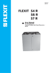
1
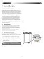
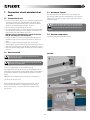
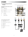
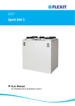
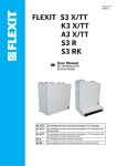
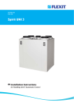
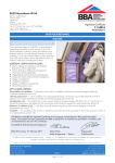
102608E-01
2009-10
Flexit SPIRIT K2 R
User manual and
installation instructions
Air handling unit with kitchen hood
Contents
User instructions
1
2
3
4
Functional Description
1.1 Heating element
1.2 Operation of kitchen hood
Cleaning/Maintenance
Maintenance table
Troubleshooting
4
4
4
5, 6, 7
8
9
Installation instructions
5
6
7
8
9
10
11
12
13
14
15
Installation/Preliminaries
5.1 Inspection/Maintenance
5.2 Space Required
5.3 Location requirements
5.4 Recommended sound attenuation for wall-mounting
I nstallation of Flexit SPIRIT K2 R
6.1 Installing the volume hood
Connection of unit and electrical work
7.1 Connection of unit
7.2 Electrical work
7.3 Automatic Control
7.4 External components
Sizes/Physical Dimensions
8.1 Dimensioned sketch
General Drawings and System Drawings
Capacity and sound data
10.1 Capacity diagram, sound data, specifications - K2 R AC
10.2 Capacity diagram, sound data, specifications - K2 R EC
Technical data
Adjusting the Kitchen Hood
12.1 Forced Ventilation
Adjustment Curves
13.1 Forced ventilation
Final checks/first use
14.1 Final Checks
14.2 First use
EC Declaration of Conformity
10
10
10
10
11
12
12
13
13
13
13
13
14
14
15
16
16
17
18
19
19
20
20
21
21
21
22
Our products are subject to continuous development and we therefore reserve the right to make changes.
We also disclaim liability for any printing errors that may occur.
2
!
Important Safety Instructions:
It is the installer's responsibility to carry out a full safety and function assessment of the appliance
To reduce the risk of fire, electric shock or injury, read all the safety instructions and warning texts before
using the appliance.
• This unit is only designed for ventilation air in buildings.
• It must not be used to extract combustible or flammable gases.
• Remove the power plug before commencing any service and maintenance work.
• Before opening the door, current to the unit must be turned off and the fans must have had time to stop (min. 3 mins.).
• The unit contains heating element which must not be touched when it is hot.
• The unit must not be operated without the filters being in place.
• Do not cook substances which could catch fire under the ventilator.
• Do not leave a saucepan or frying pan containing oil or grease unsupervised.
• Follow the instructions in the user manual.
To maintain good indoor air quality, comply with regulations and to avoid condensation damage the unit must never be stopped
apart from during service/maintenance or in connection with an accident.
Symbols Used
These products bear a number of symbols used for
labelling the
and user
6 actual product and in installation
5
documentation.
4
3
2
HIGH VOLTAGE
D
DANGER! DO NOT TOUCH
14,0
SAFETY SWITCH
C
35,0
!
CAUTION When a text bears this symbol, it
means that personal injury or serious damage to
the equipment may result if the instructions are
not followed.
NB! When a text bears this symbol, damage to
equipment or a poor utilisation ratio may result if
instructions are not followed.
B
Type:
Material:
EXAMPLE OF NIPPLE LOCATION
(shown as right-hand model)
A
Description
3
6
Opaque
Glossy vinyl
According to IEC/EN 60335-1 Colour:
White
Adhesiv:
Note that the product is not designed
for operation byPermanent
person with impaired
physical, motor or mental abilities. The product must also not be used by
persons who lack experience or knowledge, unless they have received guidance or instructions in operating the product safely by a person responsible
Projection
Date
Drawn
Scale
for safety.
24.03.2009
leif
Approved
Status
2:1
5
4
3
Etikett sikkerhetsbryter
Project
G2-1A
Stocknumber
102732
2
Replace
For user
1 Functional Description
See page 15 for component description.
Cold outdoor air passes through one half of the rotor
(HR-R), while warm extract air passes through the other half,
without the two mixing. Using this principle, a large proportion
of the heat in the extract air is transferred to the supply air the heat store principle (see system sketches). If the outdoor
temperature is extremely low, a thermostat-controlled
heating element (EB1) also ensures that the supply air has
the desired temperature. This supply air is passed via ducts
and valves to living rooms and bedrooms. The extract air
is extracted either from the same room or via door gaps/
overflow gratings to toilets and wet rooms. The used air is
passed via a duct system back to the unit, gives off its heat
and is expelled from the building via a roof cowl, combi-box
or wall grating.
When there is no need for heat recovery (for example in the
summer), the rotor stops.
1.1 Heating element
The heating element is protected against overheating by
the thermostat (F20), which switches off at 60°C. As an
additional safety measure, the thermostat (F10) switches
off at 85°C. Thermostat F10 needs to be reset manually by
pressing the reset button.
6
You will find the thermostat by opening the unit doors
(located directly over the heating element).
D
5
6
4
5
3
4
2
3
1
2
Fig. 1
D
1.2 Operation of kitchen hood
A - Knob for damper and for forced ventilation
B - Pushbutton for light
When cooking, open the damper by turning damper switch A.
B (1:1)
1) Turn the knob to level 1. The damper will beC half open.
C
2) Turn the knob to level 2. The damper will be fully open.
3) Turn the knob to level 3 and the unit will increase the air
volume to speed 3 (forced ventilation).
4) You will need to turn the damper back manually (when
cooking is finished).
B
B (1:1)
B
A
B
B
This is purely a ventilation system and not a
heating system. The home must be heated in the
normal manner.
B
Date
18.02.2009
Status
A
A
6
5
4
5
4
4
3
Scale
leif
Date
Drawn
Approved
18.02.2009
leif
Project
Description
Stocknumber
Project
Stocknumber
Projection
Replaces:
Scale
1:5
Replaced by:
Replac
G2-1A
3
1:5
Approved
Status
Description
6
Projection
Drawn
351600
G2-1A
2
2
1
For user
2 Cleaning/Maintenance
Fans:
The fans must be cleaned once a year. Clean the fan
blades with a grease solvent on a cloth - or with brush and
compressed air if possible. NB! Do not use water.
Dismantle the fan as follows: Open the doors as instructed.
EC fan: Release the screw at the front of the fan. Pull out the
electric quick-release contact for the motor. The fan can
now be pulled carefully down and out of the unit.
AC fan: Pull the fan out half way. Pull out the contact behind
the fan. The fan can now be pulled out.
Before opening the door of the heat recovery
! unit or carrying out maintenance on the kitchen
hood: switch off the heat, let the fans continue for three
minutes to remove hot air, disconnect power from the
unit and wait 2 minutes before opening the doors.
!
Remember first to remove the safety lock at the
top of the door.
Filters: To preserve a healthy indoor air quality, it is important to
change filters when they are dirty. Dirty filters lead to:
Increased air resistance in the filter – less air in
! the home – risk of bacterial growth in the filter
– in the worst case scenario, the system can be
damaged.
safety lock
!
How often the filters need to be changed depends on the
degree of contamination of the air where they are installed.
In general, the filters need to be changed once a year,
preferably in the autumn (after the pollen season). In areas
with a lot of dust and contamination, the filters should be
changed in the spring and autumn. The supply air filter and
extract air filter consist of a compact filter (F7). These are
pushed into place.
It is recommended that you order a filter subscription to
ensure full benefit from the system and the cheapest prices.
Remember that the door is heavy (10 kg) when
lifting it off the unit.
When changing the filter, check that the whole unit
is working normally.
2
1
Rotor: As the unit has filters with a high impermeability class
installed, it is not usually necessary to clean the rotor. If
for various reasons it should still be necessary, dust can
be removed with a soft brush. Further cleaning is possible
if you remove the rotor, spray it with fat-soluble detergent
and then blow it clean from the opposite side. Distance
approximately 60mm and max. pressure 8,0 bar. Ensure that
the motor is not exposed to water during cleaning. Ensure
that all seals around the rotor are intact and tight.
3
External cleaning:
Many kitchen surface cleaners contain chemicals that
may damage the product’s plastic components. Therefore
use a soft cloth moistened with warm water and a neutral
detergent to clean the outside of the product.
Important! Do not use abrasive cleaners or scouring
powder, as they will damage the colour. Products that give
stainless steel an anti-fingerprint coating must not be used
either.
Fig. 2
1. Hold the door by its upper edge, which has a recessed
grip.
2. Pull the door to release it from its catch.
3. Change your grip and lift the door off. NB! The door
weighs 10 kg.
5
6
6
Do not use detergent that is harmful to
5
aluminium or the environment.
5
5
4
Mounting of door:
4
4
3
3
3
2
2
2
1
Fig. 3
2
1
C
C
1. Lower the front edge of the door into the leading edge
C (of1 : 2 )
the unit.
2. The guide pins on the door must pass through the base of
the unit.
3. Push the top edge of the door to lock it.
C
3
C (1:2)
C (1:2)
Date
Date
12.02.2009
6
5
5
5
4
4
4
Approved
Status
Approved
Description
Description
Description
Project
Stocknumber
3
6
Projection
Repl
Replaces:
ProjectStocknumber
Stocknumber
3
Scale
Scale
leif
Status
Project
6
Drawn
leif Projection
Date 12.02.2009
Drawn
Projection
DrawnStatus
Approved Scale
12.02.2009
leif
3
2
2
2
Replaces:
Replaced
351
351600_dør
1
009
For user
Kitchen hood:
Wipe the volume hood with a damp cloth and detergent.
The filter must be cleaned roughly twice a month with normal
use. Dismount the filter (see figs. 4 and 5) and place it in hot
2 liquid. The filter cassette can also
1 be
water with washing-up
washed in the dishwasher. Several times a year the volume
hood should be cleaned internally. Wipe it internally with a
damp cloth and detergent. Replace the filter cassette and
press it up so that it fixes to the snap locks.
To change the fluorescent tube, remove the lamp glass
by pressing the snap locks in the direction of the arrow,
Fig. 6.
The fluorescent tube can now be accessed for
replacement.
The risk of fire increases if the volume hood is not cleaned as
often as specified.
6
3
D
International Philips
ILCOS code
designation
Osram
designation
Light
D
source
FSD-11-G23
DULUX-S
Power
11W
11W
Earth
G23
G23 2-pin
5
PL-S 2-pin
4
11W
3
G23 2-pin
Fig. 6
Fig. 4
C
4
C
3
2
1
B
D
2
3
Date
Drawn
Status
Approved
19.02.2009
A
Projec
leif
Description
Project
G2-1A
Stocknumber
Fig. 5
6
5
4
3
B
C
Drawn
leif
Projection
Scal e
Approved
A
Replaces:
er
2
Replaced by:
351600
1
B
7
For user
3 Maintenance table
Component
Filters
Interval
Filters should be changed at least once a year. You are advised to change them twice a year.
6-12 months
Before and after the pollen season. Check that the filter seal is completely tight.
Fans
Fans should be cleaned at least once a year to maintain fan efficiency.
12 months
Heat exchanger Check that the surfaces are clean. Check that the sealing strips lie in against the heat exchanger. 12 months
Make sure that rotor driving belt is in good condition and well adjusted.
12 months
Kitchen hood
Wash the grease filter. Check that the damper is clean and closes fully.
2 weeks
Seals
Check that the seals in the unit are intact.
12 months
Valves
To be cleaned at least once a year.
12 months
Air intake
Check that no leaves and other items are caught in the grille.
12 months
Roof cowl
If the unit has a roof cowl, this must be checked for leaves and the like.
12 months
Also check that the drain slots are open.
Ducts
Check that the ducts are clean.
10 years
8
For user
4 Troubleshooting
In the case of a power cut, the unit will automatically return to normal operation (user's settings)
when starting up again.
The unit has a safety switch which cuts off
power when the door is removed.
Type of fault:
Remedial action:
Cold draughts
Check which supply temperature has been selected. See operating panel.
Check that the rotor is rotating.
Check that heating comes on.
Needs new extract filter.
Fans not working
Check that the power to the unit is connected.
Check that the overheating thermostat has not cut out.
Reset by pressing the button. Also needs correcting on the automatic control panel.
Check that the unit has not been set in stop position.
Low air volume
Check the speed the unit is set to.
Check that the filters fit tightly.
Check the intake grille.
For other types of fault which close down the
control panel/manual terminal,see separate instructions for the automatic control system.
If none of this helps, please contact your supplier for service. Please state the model designation and serial number (on the rating plate
inside the unit/open door).
9
For fitter
Installation Instructions
5Installation/Preliminaries
5.3 Location requirements
The unit has been designed for location in the kitchen over
the cooker as it contains an integrated kitchen hood. The
unit is available in left or right versions
(exhaust air nipple to the left or right), depending on what is
the most favourable in relation to the duct location.
See separate documentation for installation of ducts, valves,
etc.
The unit is designed for indoor installation.
5.1 Inspection/Maintenance
The unit must be installed with space for service and
maintenance such as filter replacement and cleaning the
fans and recovery system.
The control cable with plug for automatic control on top of
the unit must be easily accessible.
5.2 Space Required
Type
A
B
C
K2 R
335 mm
2 x 2 mm
215-380 mm
A: Space in front of unit
B: Space at side of unit
C: Space above unit
These are minimum requirements and only take service
needs into account. National statutory requirements for
electrical safety may deviate from this. Check which rules
apply in your country.
B=2mm
B=2mm
596mm
596mm
Cover on top of unit
(optional extra)
C=215-380mm
C=215-380mm
Fig. 7
Filter
Filter
A=335mm
70mm
(volume hood)
(filter)
700mm
(unit)
A=335mm
845mm
10
B=2mm B=2mm
For fitter
5.4 Recommended sound attenuation for
wall-mounting
For wall mounting, the (included) wall bracket fixed to the unit
is used.
The unit must not be placed on a wall with rooms on the
other side which are sensitive to noise. The wall must be
sound-insulated. If necessary, use double plasterboards on
the wall.
Interrupted studs must be used.
min 600 mm
steinull
gips
Min. req. 450mm
Recommended
500mm*
min 500(650)
mm
720 mm
40 mm
spikerslag
*min. req. 650mm for gas cookers
11
For fitter
6Installation of Flexit SPIRIT K2 R
Fig. 10
B=2mm
B=2mm
596 mm
Flexit SPIRIT K2 R is designed for installation in the kitchen
above the cooker, see Fig. 11. The unit is supplied in left and
right-hand versions depending on what suits duct locations
best (Chap. 5.1).
The unit must be wall-hung from a mounting bracket (Fig. 8)
at the top using the enclosed screws. It must also be screwed
to the wall at the bottom edge of the unit. Remove 2 plastic
plugs to access the mounting holes. For secure mounting, it is
necessary to use extra nailing strips (noggins). The location
of these is shown in Fig. 8.
NB! The wall must have good sound insulation, see Chap. 6.4.
The wall must be completely flat behind the ventilation unit.
If the kitchen hood area is tiled, a suitable liner plate must be
mounted behind the unit. The distance between the bottom
of the grease filter and the cooker should be at least 50 cm
for electric cookers and 65 cm for gas cookers. For the
external dimensions of the unit, see the dimensioned drawing
in Chap. 5.1.
6.1Installing the volume hood
Fig. 11
rockwool
Fig. 8
steinull
min 600 mm
gypsum
gips
fixing, top edge
Recommended
min500mm*
500(650) mm
fixing lower edge
Fig. 9
A
1
1
33
*min. req. 650mm for gas cookers
2
2
1. Mount the two sides.
2. Attach the two angles.
3. Fix the glass profile.
12
Min. req. 450mm
720 mm
40 mm
studs
spikerslag
For fitter
7 Connection of unit and electrical
work
7.3 Automatic Control
The control pack is included in the unit package. The
low-voltage cable must be laid between the unit and the
switch unit. See separate manual for automatic control
included in pack.
7.1 Connection of unit
• Ensure that the ducts arrive at the right muff coupling. See
the marking on the unit (top/bottom and behind door).
The symbols are explained on page 3 and the location is
shown in the dimensioned drawing in Chap. 5.
• Pull the duct insulation well up to the unit.
• To avoid condensation, it is very important for the outdoor
air duct and the exhaust air duct to have insulation and a
plastic muff pulled right down to the unit.
NB! Use tape to seal the plastic sleeve to the unit
but do not compress the insulation.
• Lay the outdoor air duct with a slight incline towards the
outdoor air cap so that any water that enters drains out
again.
• If there is a short distance between the unit and the
exhaust point, sound insulation must be installed to ensure
that the requirements for the outdoor sound level are met.
• Ducts must have good sound insulation, particularly above
the unit.
The low-voltage cable must be laid minimum
30 cm from the 230 V cable and in the case of
chased mounting be laid in 20 mm electrical
piping.
7.4External components
See wiring diagram enclosed with unit.
7.2Electrical work
Service
All electrical work must be carried out by authorised personnel.
1
The unit must be installed with a separate earth
leakage circuit breaker.
The unit is suppied with a 1.8 m cable with plug.
The cable leaves the top of the unit and is connected to a
230V 50 Hz single-phase earthed power point located within
a convenient distance. The plug must be used as a service
switch.
NB! Make sure the power point for the unit is not boxed in.
See Chap. 13 for fuse sizes.
A low-voltage cable (with connector) leaves the unit for
use on the control panel. It is important to retain easy
access to this plug - in case of any fault or when replacing the unit.
2
13
For fitter
8 Sizes/Physical Dimensions
8.1 Dimensioned sketch Flexit SPIRIT K2 R
(Shown as left-hand model)
(Shown as right-hand model)
371
371
84
229
229
129
129
84
227
227
514
514
14
For fitter
9 General Drawings and System
Drawings
(Shown as left-hand model. The right-hand version is a mirror image.)
Outdoor Supply Extract Exhaust
air
air
air
air
General Diagram (Rotary Wheel-type Heat
Exchanger)
1 (FI2)
Extract filter F 7
2 (FI1)
3 (EB1)
Supply air filter F 7
Heating element
4 (F10-20) Overheating thermostat (heating) (Reset)
5 (M1)
9
Control unit
10
Kitchen hood
11 Adjustment switch
12
Damper adjustment
2
1
8
6 (M2)
Extract air fan
7 (HR-R) Rotary wheel-type heat exchanger
Rotor motor
4
7
Supply air fan
8 (M4)
3
6
5
12
11
9
10
utdoor O
air
SupplyExtract
air
air
Exhaust
air
System drawing (electric battery)
B1
Supply air temperature sensor
EB1 Heating element
F10 Overheating thermostat, manual reset
F20 Overheating thermostat, automatic reset
FI1
Supply air filter
FI2 Extract air filter
M1 Supply air fan
M2 Extract air fan
HR-R Rotary wheel-type heat exchanger
M4 Rotor motor
K
Kitchen hood
DA4 Damper
B1
EB1
FI1
FI2
F10
F20
M4
HR-R
M2
M1
DA4
K
15
For fitter
10 Capacity and sound data
10.1 Capacity diagram, sound data, specifications - K2 R AC
Supply air side (with F7 filter)
20
40
80
60
400
80
300
60
Power consumption in Watt
Contact resistance (Pa)
l/s 0
230V
200
100
Pa
40
190V
170V
150V
120V
105V
85V
60V
60V
0
85V
120V
105V
230V
190V
170V
150V
60dB(A)
55dB(A)
50dB(A)
20
70dB(A)
65dB(A)
m3/h
0
Yellow field: SFP < 1.0 per fan
0 W
200
100 m 3 /h - Pressure correction
Air flow rate,
factor
300
Extract air side (with F7 filter)
20
40
80
60
400
80
300
60
230V
200
190V
170V
150V
120V
105V
85V
60V
100
m3/h
40
120V
105V
230V
190V
170V
150V
85V
55dB(A)
60V
50dB(A)
45dB(A)
Pa 0
0
Power consumption in Watt
Contact resistance (Pa)
l/s 0
20
64dB(A)
60dB(A)
0 W
200
100
Air flow rate,
m 3 /h - Pressure correction
factor
Sound data is given at sound power level LwA in the capacity diagrams
and is corrected with the table below for the various octave bands.
Radiated noise produces Lw in the various octave bands and total
LwA. This is read directly from the supply air table.
Yellow field: SFP < 1.0 per fan
300
Data for supply air is measured in accordance with ISO 5136,
"In-duct method".
Radiated noise is measured in accordance with ISO 9614-2.
Bruel & Kjær measuring equipment, type 2260.
Correction factor for
Air capacity at various capacity settings in Volt.
Supply air fan power consumption at various capacity settings.
Sound power level LwA, cf. correction table.
Hz
63 125 250 500 1000 2000 4000 8000 LwA
Supply air 3
2 -2
-5
-5
-6
-13
-29
Extract air 18 14
1
-12
-14
-28 -37
-43
Radiated -46 -39 -29 -36 -40
-44 -54
-58 -33,5
16
For fitter
10.2Capacity diagram, sound data, specifications - K2 R EC
Supply air side (with F7 filter)
20
40
80
60
400
80
300
60
200
100%
40
100%
80%
100
Pa
0
60%
40% 40%
80%
20
60%
65dB(A)
55dB(A) 60dB(A)
Power consumption in Watt
Contact resistance (Pa)
l/s 0
Yellow field: SFP < 1.0 per fan
70dB(A)
0 W
m3/h
0
200
100
Air flow rate, m 3 /h - Pressure correction factor
300
Extract air side (with F7 filter)
20
40
400
80
300
60
200
40
100%
100%
80%
100
60%
40%
Pa
0
m3/h
0
80%
20
60%
40%
63dB(A)
60dB(A)
55dB(A)
0 W
45dB(A)50dB(A)
Air flow rate, m 3 /h - Pressure correction factor
100
200
Sound data is given at sound power level LwA in the capacity diagrams
and is corrected with the table below for the various octave bands.
Radiated noise produces Lw in the various octave bands and total
LwA. This is read directly from the supply air table.
Yellow field: SFP < 1.0 per fan
300
Data for supply air is measured in accordance with ISO 5136,
"In-duct method".
Radiated noise is measured in accordance with ISO 9614-2.
Bruel & Kjær measuring equipment, type 2260.
Correction factor for Lw
Hz
Supply air
Extract air
Radiated
80
60
Power consumption in Watt
Contact resistance (Pa)
l/s 0
Air capacity at various capacity settings in %
Supply air fan power consumption at various capacity settings.
Sound power level LwA, cf. correction table.
63 125 250 500 1000 2000 4000 8000 LwA
3
2 -2
-5
-5
-6
-13
-29
18 14
1
-12
-14
-28 -37
-43
-41 -35 -33 -39 -40
-49 -50
-60 -33,5
17
For fitter
11 Technical data
11.1Technical data Flexit SPIRIT K2 R
Rated voltage
Fuse size
Rated current, total
AC
230 V/50 Hz
10 A
3.85 A
EC
230 V/50 Hz
10 A
4.0 A
Rated power, total
900 W
930 W
Rated power, electric batteries
700 W
700 W
Output fans
2 x 60 W
2 x 76 W
Fan type
B-wheel
F-wheel
Fan motor control
Max. fan speed
Automatic control standard
Filter type (SUP/EXTR)
Transformer
2,500 RPM
CS 50
F7/F7
0-10 V
1,970 RPM
CS 50
F7/F7
SUP filter dimensions (WxHxD)
130x335x50 mm
130x335x50 mm
EXTR filter dimensions (WxHxD)
Weight
Duct connection
Duct connection kitchen fan
Height
Width
Depth
130x335x50 mm
130x335x50 mm
56 kg
56 kg
Dia. 125 mm (sleeve) Dia. 125 mm (sleeve)
700 mm*
598 mm
510 mm**
700 mm*
598 mm
510 mm**
* without volume hood and duct connection, see Chap. 5
** see Chap. 5
18
For fitter
B (1:1)
12 Adjusting the Kitchen Hood
If basic ventilation is desired via the kitchen hood, the
damper from the factory must be replaced. Replace it with a
damper with adjustment options. This is not supplied with the
unit.
C
12.1 Forced Ventilation
The unit has 4 forced ventilation options:
1. (Switch on front of unit.) This gives a half-open damper
which will increase the air volume passing through the hood.
B
2. Turn the knob to position 2. This gives a fully open
damper which will allow even more air through the kitchen
hood.
3. Turn the knob to position 3. This will give a fully-open
damper which will allow even more air through the kitchen
hood, in that the fans go to speed 3.
4. The air volume through the unit can also be increased by
setting the fans to speed 3 via the control panel (external
panel). See separate instructions.
The damper needs closing again manually. There is no timer
in the damper. Closed in position O.
the unit throughProjection
the kitchen hood does not
Date The air entering
Drawn
Scale
pass through the rotary heat exchanger (by-pass).
18.02.2009
Status
leif
1:5
Approved
A
Replaces:
Description
Project
G2-1A
Replaced by:
351600
Stocknumber
2
1
19
For fitter
13 Adjustment Curves
13.1 Forced ventilation Flexit SPIRIT K2 R
Max. air volume through kitchen hood in case of forced air volume
Measurements have been taken at 2/3 pressure in the
extract air duct and 1/3 pressure in the exhaust air duct
before opening the damper.
20
For fitter
14 Final checks/first use
14.1 First use
14.1 Final Checks
• Check that the control panel has been connected.
• Plug the unit into the mains supply.
• The unit will now start.
• The unit will automatically perform a start-up procedure
lasting approx. 2 min.
• After the start-up procedure the unit will follow the settings
entered on the control panel.
• If it is wished to check or alter the settings, this can be
done from the control panel.
(See separate documentation for automatic control.)
Check that:
• The duct insulation is in accordance with the manual
and the technical documents. It is very important the
ducts from the unit are also effectively insulated so that
no condensation forms on or in the ducts. It is especially
important to check this if the ducts are to be boxed in.
• Ducts are connected to the right nipples – check against
the unit drawings below.
• Adjustments have been made in accordance with the
manual and project planning documents (documentation
of ventilation data).
• The unit operates normally at all stages.
• Heating switches in.
• The unit has filters for both outdoor air and extract air.
• Tumble dryers must not be connected to the unit.
The installer may be held liable for any incorrect
or defective installation.
Flexit SPIRIT K2 R, Left-hand model
Flexit SPIRIT K2 R, Right-hand model
21
For fitter
15EC Declaration of Conformity
This declaration confirms that the products meet the
requirements in the following Council Directives and
standards:
89/336/EEC Electromagnetic Compatibility (EMC)
73/23/EEC Low-voltage Directive (LVD)
98/37/EEC Machine Directive (Safety)
Manufacturer:
Ørje, Norway
FLEXIT AS, Televeien 15, 1870
Type:
Ventilation unit
K2 R
Conforms to following standards:
Safety standard
EN 60335-1:2002
EMF standard:
EN 50366:2003
EMC standard:
EN 55014-1.2000
EN 61000-3-2:2000
EN 61000-3-3:1995
EN 55014-2:2:1997
The product has been CE-marked: 2009
FLEXIT AS 07.05.2009
Frank Petersen
CEO
The right to give notice of lack of conformity applies to this product in
accordance with the existing terms of sale, provided that the product is used
and maintained correctly. Filters are consumables.
The symbol on the product shows that this product must not be
treated as household waste. It must be taken to a reception station
for recycling of electric and electronic equipment.
By ensuring the correct disposal of the equipment, you will contribute
to preventing the negative consequences for the environment and
health that incorrect handling may entail. For further information
on recycling of this product, please contact your local authority, your refuse
collection company or the company from which you purchased it.
Notice of lack of conformity as a result of incorrect or defective installation must
be submitted to the installation company responsible. The right to give notice of
lack of conformity may lapse if the system is used incorrectly or maintenance is
grossly neglected.
22
23
Flexit AS, Televeien 15, 1870 Ørje, Norway
www.flexit.com