1
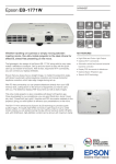
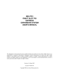
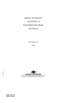
600-2703
PCI EXPRESS
EXPANSION SYSTEM
USER’S MANUAL
The information in this document has been carefully checked and is believed to be entirely reliable. However, no
responsibility is assumed for inaccuracies. Furthermore, Cyclone Microsystems, Inc. reserves the right to make
changes to any products herein to improve reliability, function, or design. Cyclone Microsystems, Inc. neither
assumes any liability arising out of the application or use of any product or circuit described herein, nor does it
convey any license under its right or the rights of others.
Revision 1.1, April 2007
Cyclone P/N 800-2703
Copyright 2006 by Cyclone Microsystems, Inc.
CONTENTS
CHAPTER 1
1.1
INTRODUCTION ..............................................................................................................................1-1
1.2
SPECIFICATIONS............................................................................................................................1-3
1.3
STANDARDS ...................................................................................................................................1-3
CHAPTER 2
2.1
THEORY OF OPERATION ..............................................................................................................2-1
CHAPTER 3
3.1
600-2703 CHASSIS..........................................................................................................................3-1
3.2
POWER CONSIDERATIONS...........................................................................................................3-1
CHAPTER 4
4.1
SYSTEM POWER UP ......................................................................................................................4-1
4.2
SEATING OF CARDS ......................................................................................................................4-1
4.3
LINK INDICATION - LED DEFINITION PCIe-408 ............................................................................4-1
4.4
LINK INDICATION - LED DEFINITION PCIe-403 ............................................................................4-2
4.5
LINK INDICATION - LED DEFINITION PCIe-412 ............................................................................4-2
CHAPTER 5
5.1
PHYSICAL CONFIGURATION.........................................................................................................5-1
CHAPTER 6
6.1
i
REFERENCE MANUALS .................................................................................................................6-1
600-2703 PCI Express Expansion System User’s Manual
Revision 1.1, April 2007
CHAPTER 1
INTRODUCTION
1.1
INTRODUCTION
The Cyclone Microsystems’ 2703 PCI Express Expansion System is a PCI Express (PCIe) expansion
system that allows the user to add up to thirteen PCI Express and two PCI-X add-in cards. Most PCs
contain few PCI Express slots making them poorly suited for embedded systems requiring a wealth of
different I/O boards and co-processor resources.
The 2703 PCI Express Expansion Systems permits system developers to use powerful and costeffective PCs as a foundation for a robust embedded system. The thirteen PCI Express slots are
organized as five x8 slots and eight x4 slots. All expansion slots accommodate full length and full eight
cards and are cooled by four 50 CFM fans. A 550 watt supply powers the rack mounted expansion
chassis.
The Expansion System supports 20 Gb/s bi-directional traffic to and from the host system and utilizes
non-blocking PCI Express switches for excellent peer-to-peer I/O bandwidth. For PCs with modern
BIOSs, the 2703 Expansion System is recognized by the host system upon boot-up, requires no
hardware specific drivers, and is entirely host operating system agnostic.
The 600-2703 system is composed from three elements: a PCI Express Host Bus Cable Adapter, an
Expansion System Cable and an Expansion Chassis. Our PCIe-408 Host Cable Bus Cable Adapter card
is inserted into a host computer’s PCIe slot. PCIe expansion cable links the PCI host with the expansion
chassis. The expansion chassis is populated with two boards, a PCIe-403 SHB Expansion Cable
Adapter which is inserted in to the PCIe-412 Switched Backplane.
In an alternate configuration, (600-2602), the PCIe-412 and rack-mount chassis can be populated with a
PICMG 1.3 System Host Board and function as a stand-alone embedded system.
PCI Express is a high performance, general purpose I/O inter-connect defined for a wide variety of
computing and communication platforms. Key PCI attributes, such as its usage model, load-store architecture, and software interfaces are maintained, whereas its parallel bus implementation is replaced by a
serial interface. PCI Express take advantage of recent advances in point-to-point inter-connects, Switchbased technology, and packetized protocol to deliver new levels of performance.
600-2703 PCI Express Expansion System User’s Manual
Revision 1.1, April 2007
1-1
INTRODUCTION
Figure 1-1. 600-2703 Block Diagram
1-2
600-2703 PCI Express Expansion System User’s Manual
Revision 1.1, April 2007
INTRODUCTION
1.2
SPECIFICATIONS
The specifications in table 1-1detail the 600-2703 expansion system chassis including the PCIe-412
expansion backplane, the PCIe-403 PICMG 1.3 slot cable adapter and the 500W power supply. The
chassis also includes four 50 CFM fans.
Table 1-1. Specifications
Physical
Electrical
Environmental
1.3
Height
6.969 inches
Width
17 inches
Depth
26.256 inches
Other
19 inch rack mountable
Voltage
90 ~ 263 VAC full range
Frequency
47 ~ 63 Hz.
Input Current
8.0 A for 115 CVAC, 4.0 A for 230
VAC.
Inrush Current
65 A max. for 115 VAC, 125 A
max. for 230 VAC.
Fuse
8.0 A at 250 VAC
Operating Temperature
0 to 40 Degrees Celsius
Relative Humidity
0% to 95% (non-condensing)
Storage Temperature
-20 to 70 Degrees Celsius
STANDARDS
PCI Express Base Specification Revision 1.1
PCI Express Card Electro Mechanical Specification 1.1
PCI Express External Cabling Specification 1.0
PICMG SHB Express Revision 1.0
600-2703 PCI Express Expansion System User’s Manual
Revision 1.1, April 2007
1-3
CHAPTER 2
THEORY OF OPERATION
2.1
THEORY OF OPERATION
The basic PCI Express Link consists of dual unidirectional differential links, implemented as a transmit
pair and a receive pair. The signaling rate for PCI Express is 2.5 Gigabits/second/Lane/direction. A
link supports at least one Lane.
The PCI Express link from the PCIe-408 over the cable to the PCIe-403 is an eight lane (x8) link. The
PCIe-412 provides six x8 slots and eight four lane (x4) slots. Note that in the installed chassis, 6002703, there are only 5 available x8 slots due to one slot being obstructed by the power entry module for
the chassis. Each slot can accommodate either single lane (x1), x4 or x8 add-in cards. In the case where
a x8 add-in card is installed into a x4 slot, only the first four lanes on the add-in card will be utilized.
This situation is termed “down-shifting”. Per the PCI Express Specification, down-shifting is only
allowed in this case. All slot connectors on the PCIe-412 are mechanically x8 with the x4 slots leaving
the upper four lanes not connected. Up-plugging, i.e., plugging a smaller link card into a larger link
connector, is fully allowed.
Once the PCIe-408 is installed into the host PC, the cable connected to the PCIe403, the chassis is
plugged into an AC power outlet and any desired add-in cards are installed, the system is ready to be
turned on. A number of things happen at this point. First, the PCI Express links are initialized. This is
a purely hardware initialization where each PCI Express link is set up following a negotiation of lane
widths by the two ends of each link. No firmware or operating system software is involved. Once the
links are initialized or “trained”, there are LED indicators on each of three Cyclone Microsystems’
cards that indicate both the links that are trained and the individual lanes. A detailed explanation of the
LEDs follows later in this manual.
One essential requirement for system initialization is the ability of the Host system’s BIOS to be able to
enumerate the many bridges inherent in a complex PCI Express design. The links from the PCIe-408
through the PCIe-403 to the PCIe-412 are created with PCI Express Switches. Each link looks like a
PCI-to-PCI bridge to the Host’s BIOS. The number of bridges can add up quickly. Older BIOS may
not have the ability to handle the number of bridges. Make sure that the BIOS on the host computer has
the latest updated BIOS. If required, contact the host system’s manufacturer to make sure that the BIOS
used can handle the large number of bridges that it will see in the system.
600-2703 PCI Express Expansion System User’s Manual
Revision 1.1, April 2007
2-1
CHAPTER 3
EXPANSION SYSTEM OPERATION
3.1
600-2703 CHASSIS
The PCIe-412 is installed into is a 20 slot rack mountable chassis. The chassis provides access to five x8
PCI Express slots, eight x4 PCI Express slots and two PCI-X slots. All slots can accommodate standard
height and full length PCI Express and PCI-X add-in cards. The chassis also contains three drive bays
that may be used by the user to install anything for their particular application. There are several ATX
four pin peripheral power connectors available from the power supply.
The chassis contains a 500W power supply. Tables 3-1 through 3-5 show the power consumption for the
Cyclone Microsystems boards and the power supplied to the PCI Express and PCI-X slots. However,
the power supply is not designed to supply maximum power to each slot and it is up to the user to
determine if total load of their add-in cards is acceptable. Note that the PCIe-408 is installed in and
powered by the host supply. After subtracting the PCIe-403 and PCIe-412 board, there is 451.2W of
power remaining for all add-in cards. Table 3-6 shows the amount of current per supply rail that is
available. Again, note that the maximum currents listed exceed the power available. Taking into consideration the maximum power that can be supplied to a particular slot, the current available per supply rail
and the total power available to the system, one can determine the number of add-in cards that can be
installed into the 600-2703. Additionally, if the user installs any peripheral devices into the available
drive bays and utilizes power from the peripheral power connectors, this power would also have to be
subtracted from the total power available.
As an example, if a user had identical PCI Express cards that draw 2.0A of +3.3V and 1.4A of +12V,
that would be a total of 23.4W. The power draw for the card is below 25W, the PCI Express Specification for the maximum power for a add-in card, so this board may be used in the PCIe-412. In this
case, all thirteen available PCI Express slots can be filled, since the +3.3V draw would be 26A and the
+12V draw would be 18.2A and the total power draw would be 304W. However, if one would like to
add a PCI-X board to this configuration, there would be 147W available, but only 1.8A of +3.3V
available.
3.2
POWER CONSIDERATIONS
Table 3-1. PCIe- 412 Power Requirements
Voltage
Current Typical
Current Maximum
+3.3V
1.2 Amps
1.4 Amps
+5V
5.4 Amps
6.9 Amps
+12V
0.02 Amps
0.04 Amps
Table 3-2. PCIe- 403 Power Requirements
Voltage
Current Typical
Current Maximum
+3.3V
0.61 Amps
0.72 Amps
+12V
0.43 Amps
0.57 Amps
600-2703 PCI Express Expansion System User’s Manual
Revision 1.1, April 2007
3-1
EXPANSION SYSTEM OPERATION
Table 3-3. PCIe- 408 Power Requirements
Voltage
Current Typical
Current Maximum
+3.3V
0.32 Amps
0.37 Amps
+12V
0.25 Amps
0.35 Amps
Table 3-4. Power Supplied Per PCIe Slot
Voltage
Current Maximum
Voltage Tolerance
+3.3V
3.0 Amps
+/- 9%
+12V
2.1 Amps
+/- 8%
* Required by the PCI Express Card Electromechanical Specification Revision 1.0a. Note that the total
power for each PCIe shall not exceed 25W.
Table 3-5. Power Supplied Per PCI Slot
Voltage
Current Maximum
Voltage Tolerance
+3.3V
7.6 Amps
+/- 0.3V
+5V
5.0 Amps
+/- 5%
+12V
0.5 Amps
+/- 5%
-12V
0.1 Amps
+/- 10%
Table 3-6. Power Available for All Add-in Cards
Voltage
Current Maximum
+3.3V
27.8 Amps
+5V
10.0 Amps
+12V
31.4 Amps
-12V
1.0 Amps
Airflow in the 600-2703 chassis is provided by four 50 CFM fans located across the rear of the board
installation area.
3-2
600-2703 PCI Express Expansion System User’s Manual
Revision 1.1, April 2007
CHAPTER 4
SYSTEM POWER UP
4.1
SYSTEM POWER UP
The host PC with the PCIe-408 installed controls power-up for the entire system. The PCI Express cable
should be connected between the PCIe-408 and the PCIe-403, which is installed into the PCIe-412, and
the 600-2703 power cord should be connected to the chassis and plugged in to a power socket. There is
a power button on the front of the 600-2703 Expansion Chassis but if is not connected and serves no
practical purpose in this application. When the host PC is powered on, a signal is sent over the PCI
Express cable to turn on the 600-2703. If the chassis does not power up, make sure that all cards are
seated properly, the chassis is plugged in and the PCI Express cable is connected properly. There are
only two LEDs on the front of the expansion chassis that have meaning. The PWR LED indicates that
the chassis is powered. The FANC2 LED indicates that the fans are running.
4.2
SEATING OF CARDS
Unlike standard PC applications, the 2703 Expansion Systems has a narrow lower gate that precisely
engages the lower end of the PCI Express Add-In board’s face panel. The purpose is to insure correct
electrical connectoring mating of up-plugged boards. Failure to accurately mate the lower end of the
face panel with the chassis lower gate will lead to the board not being recognized by the host.
4.3
LINK INDICATION - LED DEFINITION PCIE-408
There are many LED indicators on all three of the printed circuit boards (PCBs) that tell the user the
status of all links and individual lanes. Also, see Figure 5-4. The PCIe-408 has two banks of eight
LEDs. These LEDs are located on the top side or component side of the PCB. Each LED corresponds to
one lane of that particular link. One bank is labeled “UP LN 0” (upstream) and the other bank is labeled
“DWN LN 0” (downstream).
The eight upstream LEDs give the state of the link from the PC host that the PCIe-408 is installed into
to the PCIe-408. If the PCIe-408 is installed into a x8 of x16 slot, then all eight of the upstream LEDs
should be on. Since the PCIe-408 upstream port is an x8 link, only eight lanes of a x16 slot will be used.
If less than the eight LEDs are on, there is a problem with the link between the PC host and the
PCIe408. If the PCIe-408 is installed into a x4 PCIe slot (down-shifting), then only the first four LEDs
will be on and the link is trained at x4. If none of the upstream LEDs are on, turn off the host PC and
make sure that the PCIe-408 is properly seated into the PCIe connector.
The eight downstream LEDs indicate the status of the link connecting the PCIe-408 to the PCIe-403 via
the PCI Express cable. If the PCIe-408 is installed into an x8 or a x16 slot and the eight upstream LEDs
are on, the PCIe-408 is connected via the PCIe cable to the PCIe-403, all eight of the downstream LEDs
should be on. If the PCIe-408 is installed into a x4 slot, there still should be all eight downstream LEDs
on. If less than eight LEDs are on, check to make sure that the cable is properly connected to each
board. Also, make sure that the PCIe-403 is properly seated into the PCIe-412.
600-2703 PCI Express Expansion System User’s Manual
Revision 1.1, April 2007
4-1
SYSTEM POWER UP
4.4
LINK INDICATION - LED DEFINITION PCIE-403
The PCIe-403 has four groups of LEDs. The group of eight LEDs labeled “CABLE” is the upstream
link to the PCIe-408 see Figure 5-3. The groups of eight LEDs labeled “A0” and “A2” are downstream
links to PCI Express switches that drive slots 7 through 13 and slots 0 through 6, respectively. The
group of four LEDs labeled “B0” is the downstream link to the PCI Express to PCI-X bridge. Note that
all of the above LEDs should be on at all times. If any of the LEDs are not lit, there is a hardware
problem between the PCIe-403 and the PCIe-412.
4.5
LINK INDICATION - LED DEFINITION PCIE-412
The PCIe-412 has several sets of surface mount located on the top side of the PCB see Figure 5-2. The
LEDs are arranged in groups of either eight of four LEDs. As with the above boards, each LED
corresponds to an individual lane within that particular link. The are twenty one groups of LEDs and
their definition is shown in Table 4-1. Additionally, there are fourteen individual LEDs. These LEDs are
labeled PWR0 through PWR13. These LEDs are illuminated and simply indicate when an add-in card
is installed and powered in the corresponding slot. All of the LEDs labeled “UP” or “DOWN”, the
LEDs between the PCIe-403 and the PCIe-412 and between the PCI Express switches, should be on at
all times. If they are not on make sure that the PCIe-403 is seated properly into the PCIe-412. The slot
LEDs indicate the active lanes to the corresponding add-in card. If no add-in card is installed into a
particular slot, the LEDs for that slot will be off. If a x1 or x4 add-in card is installed into a x8 slot, only
1 (position 0) or 4 LEDs (LEDs 0 through 3) respectively, will be on. Similarly, x1 add-in cards
installed into x4 slots should only have the first LED on. Add-in cards that are down-shifted, x8 cards in
x4 slots, should have all four of the lane indicator LEDs on.
4-2
600-2703 PCI Express Expansion System User’s Manual
Revision 1.1, April 2007
SYSTEM POWER UP
LED LABEL
Table 4-1. PCIe-412 LED Banks
LED FUNCTION
SLOT0 0->3
Slot 0 is a four lane port
SLOT1 0->3
Slot 1 is a four lane port
SLOT2 0->3
Slot 2 is a four lane port
SLOT3 0->3
Slot 3 is a four lane port
SLOT4 0->7
Slot 4 is an eight lane port
SLOT5 0->7
Slot 5 is an eight lane port
SLOT6 0->7
Slot 6 is an eight lane port
SLOT7 0->7
Slot 7 is an eight lane port
SLOT8 0->7
Slot 8 is an eight lane port
SLOT9 0->3
Slot 9 is a four lane port
SLOT10 0->3
Slot 10 is a four lane port
SLOT11 0->3
Slot 11 is a four lane port
SLOT12 0->3
Slot 12 is a four lane port
SLOT13 0->7
Slot 13 is an eight lane port
UP A0 0->7
x8 link from the PCIe-403 to the PCIe-412 (U12)
UP 0 0->
x8 link between PCIe switches, U17 to U16
DOWN 0 0->7
x8 link between PCIe switches, U16 to U17
UP A2 0->7
x8 link between PCIe-403 to the PCIe-412 (U16)
UP B0 0->3
x4 link between the PCIe-403 and PCIe-to-PCI-X bridge
UP 1 0->7
x8 link between PCIe switches, U11 to U12
DOWN 1 0->7
x8 link between PCIe switches, U12 to U11
600-2703 PCI Express Expansion System User’s Manual
Revision 1.1 April 2007
4-3
CHAPTER 5
PHYSICAL CONFIGURATION
5.1
PHYSICAL CONFIGURATION
Figure 5-1. PCIe-412 Physical Configuration
Figure 5-1 is a physical diagram (not to scale) of the PCIe-412 adapter, showing the location designators
of jumpers, connectors, and major ICs. Refer to this figure when component locations are referenced in
the manual text.
600-2703 PCI Express Expansion System User’s Manual
Revision 1.1, April 2007
5-1
PHYSICAL CONFIGURATION
Figure 5-2. PCIe-412 LED Definition
5-2
600-2703 PCI Express Expansion System User’s Manual
Revision 1.1, April 2007
PHYSICAL CONFIGURATION
Figure 5-3. PCIe-403 LED Definition
DWN_LN7
DWN_LNO
UP_LN0
UP_LN7
Figure 5-4. PCIe-408 LED Definition
600-2703 PCI Express Expansion System User’s Manual
Revision 1.0 April 2007
5-3
PHYSICAL CONFIGURATION
Figure 5-5. 600-2703 Chassis Drawing
Figure 5-6. 600-2703 Chassis
5-4
600-2703 PCI Express Expansion System User’s Manual
Revision 1.1, April 2007
CHAPTER 6
REFERENCE
6.1
REFERENCE MANUALS
PEX 8532 Versatile PCI Express Switch Data Book Version 1.1
PEX 8114 ExpressLane PCI Express-to-PCI/PCI-X Bridge Data Book Version 1.0
PLX Technology, Inc.
Sunnyvale, CA
(800) 759-3735
www.plxtech.com
PCI Express Base Specification Revision 1.0a
PCI Express Card Electromechanical Specification Revision 1.0a
PCI Express External Cabling Specification Revision 0.7
PCI Local Bus Specification Revision 2.2
PCI-X Addendum Revision 1.0
PCI Special Interest Group (PCISIG)
5440 SW Westgate Dr., #217 Portland OR 97221
(503) 291-2569
(503) 297-1090 (Fax)
www.pcisig.org
System Host Board PCI Express Specification PICMG 1.3 Revision 1.0
PCI Industrial Computer Manufacturers Group (PICMG)
5401 Edgewater Place, #600 Wakefield MA 01880
(781) 246-9318
(781) 224-1239 (Fax)
www.picmg.org
600-2703 PCI Express Expansion System User’s Manual
Revision 1.1, Aprily 2007
6-1