1
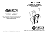
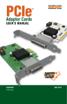
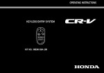
600-2706
PCI EXPRESS
EXPANSION SYSTEM
USER’S MANUAL
The information in this document has been carefully checked and is believed to be entirely reliable. However, no
responsibility is assumed for inaccuracies. Furthermore, Cyclone Microsystems, Inc. reserves the right to make
changes to any products herein to improve reliability, function, or design. Cyclone Microsystems, Inc. neither
assumes any liability arising out of the application or use of any product or circuit described herein, nor does it
convey any license under its right or the rights of others.
Revision 2.0, August 2009
Cyclone P/N 800-2706
Copyright 2009 by Cyclone Microsystems, Inc.
CONTENTS
CHAPTER 1
1.1
INTRODUCTION ..............................................................................................................................1-1
1.2
SPECIFICATIONS............................................................................................................................1-3
1.3
STANDARDS ...................................................................................................................................1-3
1.4
ORDERING INFORMATION ............................................................................................................1-3
CHAPTER 2
2.1
THEORY OF OPERATION ..............................................................................................................2-1
CHAPTER 3
3.1
600-2706 CHASSIS..........................................................................................................................3-1
3.2
POWER CONSIDERATIONS...........................................................................................................3-1
CHAPTER 4
4.1
SYSTEM POWER UP ......................................................................................................................4-1
4.2
SEATING OF CARDS ......................................................................................................................4-1
4.3
LINK INDICATION - LED DEFINITION PCIe-426 ............................................................................4-1
4.3.1 De-Emphasis .......................................................................................................................4-1
4.4
LINK INDICATION - LED DEFINITION PCIe-417 ............................................................................4-1
CHAPTER 5
5.1
PHYSICAL CONFIGURATION.........................................................................................................5-1
CHAPTER 6
6.1
i
REFERENCE MANUALS .................................................................................................................6-1
600-2706 PCI Express Expansion System User’s Manual
Revision 2.0, August 2009
CONTENTS
LIST OF FIGURES
Figure 1-1.
600-2706 Block Diagram .....................................................................................................1-1
Figure 5-1.
PCIe-417 Physical Configuration.........................................................................................5-1
Figure 5-2
PCIe-426 Physical Configuration.........................................................................................5-2
Figure 5-3
600-2706 Chassis Drawing .................................................................................................5-3
Figure 5-6
600-2706 Chassis................................................................................................................5-3
LIST OF TABLES
Table 1-1.
Table 3-1.
Table 3-2
Table 3-3
ii
Specifications ......................................................................................................................1-3
PCIe-417 Power Requirements...........................................................................................3-1
PCIe-426 Power Requirements...........................................................................................3-1
Power Supplied Per PCIe Slot.............................................................................................3-1
600-2706 PCI Express Expansion System User’s Manual
Revision 2.0, August 2009
CHAPTER 1
INTRODUCTION
1.1
INTRODUCTION
The Cyclone Microsystems’ 2706 PCI Express Expansion System is a PCI Express (PCIe) expansion
system that allows the user to add up to four PCI Express add-in-cards. Most PCs contain few PCI
Express slots making them poorly suited for embedded systems requiring many different I/O boards and
co-processor resources.
The 2706 PCI Express Expansion System permits system developers to use powerful and cost-effective
PCs as a foundation for a robust embedded system. The four PCI Express slots are organized as one x16
slot, one x8 slot and two x4 slots. All expansion slots accommodate full length and full height cards and
are cooled by one 120 CFM and two 59 CFM fans. A 650 watt supply powers the rack mounted
expansion chassis.
The Expansion System supports 40 Gb/s bi-directional traffic to and from the host system. The system
utilizes repeaters and non-blocking PCI Express switches for excellent peer-to-peer I/O bandwidth. For
PCs with modern BIOSs, the 2706 Expansion System is recognized by the host system upon boot-up,
requires no hardware specific drivers, and is entirely host operating system agnostic.
The 600-2706 system is composed of three elements: a PCI Express Host Bus Cable Adapter, an
Expansion System Cable and an Expansion Chassis. The PCIe-426 Host Bus Cable Adapter card is to
be inserted into a host computer’s x16 PCIe slot. The x16 PCIe expansion cable links the PCI host with
the expansion chassis. The expansion chassis is populated with the PCIe-417 Switched Backplane.
PCI Express is a high performance, general purpose I/O inter-connect defined for a wide variety of
computing and communication platforms. Key PCI attributes, such as its usage model, load-store architecture, and software interfaces are maintained, whereas its parallel bus implementation is replaced by a
serial interface. PCI Express take advantage of recent advances in point-to-point inter-connects, Switchbased technology, and packetized protocol to deliver new levels of performance.
600-2706 PCI Express Expansion System User’s Manual
Revision 2.0, August 2009
1-1
INTRODUCTION
PCIe-426
PCI-E 401
x16
Host PCI Express
System
Repeater
PCI-to-PCI
Bridge Link
PCI-Express x16
64-bit CompactPCI Bus
x16 PCI ExpressCable
PCIe-417 Expansion System
PCI-Express x16 Cable Interface
“D”
PCI-Express x16 Slot
“C”
PCI-Express x16 Slot
“B”
PCI-Express x8 Slot
“A”
PCI-Express x8 Slot
x16
x8
PCI-Express
Switch
x4
x4
Figure 1-1. 600-2706 Block Diagram
1-2
600-2706 PCI Express Expansion System User’s Manual
Revision 2.0, August 2009
INTRODUCTION
1.2
SPECIFICATIONS
The specifications in Table 1-1 detail the 600-2706 Expansion System chassis including the PCIe-417
expansion backplane and the 450W power supply. The chassis also includes one 120 CFM and two 59
CFM fans.
Table 1-1. Specifications
Physical
Electrical
Environmental
1.3
Height
7 inches
Width
17 inches
Depth
22 inches
Other
19 inch rack mountable
Voltage
115/230 VAC switch select
Frequency
60Hz/50Hz.
Input Current
9.0 A for 115 CVAC, 5.0 A for 230
VAC.
Inrush Current
60 A max. for 115 VAC
Operating Temperature
0 to 50 Degrees Celsius
Relative Humidity
0% to 95% (non-condensing)
Storage Temperature
-20 to 70 Degrees Celsius
STANDARDS
PCI Express Base Specification Revision 2.0
PCI Express Card Electro Mechanical Specification 2.0
PCI Express External Cabling Specification 2.0
1.4
ORDERING INFORMATION
The expansion system is avaliable with one or three meter cables and standard or low profile panels on
the Host Bus Adaptor (PCIe-426).
600-2706 PCI Express Expansion System User’s Manual
Revision 2.0, August 2009
1-3
INTRODUCTION
Cyclone Part Numbers
1-4
600-2706-3SH
Expansion System with 3 meter cable and standard
height panel
600-2706-1SH
Expansion System with 1 meter cable and standard
height panel
600-2706-3LP
Expansion System with 3 meter cable and low profile
panel
600-2706-1LP
Expansion System with 1 meter cable and low profile
panel
600-2706 PCI Express Expansion System User’s Manual
Revision 2.0, August 2009
CHAPTER 2
THEORY OF OPERATION
2.1
THEORY OF OPERATION
The basic PCI Express link consists of dual unidirectional differential links, implemented as a transmit
pair and a receive pair. The signaling rate for PCI Express is 2.5 Gigabits/second/Lane/direction. A link
supports at least one lane.
The PCI Express link from the PCIe-426 over the cable to the PCIe-417 is a sixteen lane (x16) link. The
PCIe-417 provides one x16 slot (slot D), one x8 slot (slot C) and two x4 slots (slots A and B). Slots D
and C are populated mechanically with x16 connectors; the upper eight lanes of slot C are not
connected. Slots A and B are populated mechanically with x8 connectors; the upper four lanes are not
connected. All slots can accommodate either single lane (x1), x4 or x8 add-in cards. Slots C and D can
additionally accommodate x16 cards. In the case where a x8 add-in card is installed into a x4 slot, only
the first four lanes on the add-in card will be utilized. This situation is termed “down-shifting”. Per the
PCI Express Specification, down-shifting is only allowed in this case. Although not expressly
permitted by the PCI Express Specification, slot C accommodates “down-shifting” a x16 card into x8
slot. Plugging a smaller link card into a larger link connector, is fully allowed.
Once the PCIe-426 is installed into the host PC, the cable connected to the PCIe-417, the chassis
plugged into an AC power outlet and any desired add-in cards are installed, the system is ready to be
turned on. When the host is turned on, a signal from the PCIe-426 will turn on the PCIe-417 chassis. A
number of things happen at this point. First, the PCI Express links are initialized. This is a purely
hardware initialization where each PCI Express link is set up following a negotiation of lane widths by
the two ends of each link. No firmware or operating system software is involved. Once the links are
initialized or “trained”, there are LED indicators on each of the Cyclone Microsystems’ cards that
indicate the links are trained. A detailed explanation of the LEDs follows later in this manual.
One essential requirement for system initialization is the ability of the host system’s BIOS to be able to
enumerate the many bridges inherent in a complex PCI Express design. The links from the PCIe-426 to
the PCIe-417 are created with PCI Express Switches. Each link looks like a PCI-to-PCI bridge to the
Host’s BIOS. The number of bridges can add up quickly. Older BIOS may not have the ability to handle
the number of bridges. Make sure that the BIOS on the host computer has the latest updated BIOS. If
required, contact the host system’s manufacturer to make sure that the BIOS used can handle the large
number of bridges that it will see in the system.
600-2706 PCI Express Expansion System User’s Manual
Revision 2.0, August 2008
2-1
CHAPTER 3
EXPANSION SYSTEM OPERATION
3.1
600-2706 CHASSIS
The PCIe-417 is installed into an eight slot rack mountable chassis. The chassis provides access to all
four PCI Express slots. All slots can accommodate standard height and full length PCI Express add-in
cards. The chassis also contains three drive bays that may be used by the user to install peripheral
devices for their particular application. There are several ATX four pin peripheral power connectors
available from the power supply.
The chassis contains a 650W power supply. Tables 3-1 through 3-3 show the power consumption for the
Cyclone Microsystems boards and the power supplied to the PCI Express slots. Note that the PCIe-426
is installed in and powered by the host supply. Consequently, the PCIe-426 should not be included as a
component of the Expansion Chassis power budget. In a fully populated system, with each PCI Express
add-in card drawing 25W, there is an additional 70W of +5V and 100W of +12V available for use via
the peripheral power connectors.
3.2
POWER CONSIDERATIONS
Table 3-1. PCIe- 417 Power Requirements
Voltage
Current Typical
Current Maximum
+3.3V
0.33 Amps
0.40 Amps
+5V
1.03 Amps
1.56 Amps
+12V
0.02 Amps
0.04 Amps
Table 3-2. PCIe- 426 Power Requirements
Voltage
Current Typical
Current Maximum
+3.3V
1.09 Amps
1.60 Amps
+12V
0 Amps
0 Amps
* The PCIe-426 does not use +12V
Table 3-3. Power Supplied Per PCIe Slot
Voltage
Current Maximum
Voltage Tolerance
+3.3V
3.0 Amps
+/- 9%
+12V
2.1 Amps
+/- 8%
* Required by the PCI Express Card Electromechanical Specification Revision 1.0a. Note that the total
power for each PCIe shall not exceed 25W.
Airflow in the 600-2706 chassis is provided by one 120 CFM located at the front of the chassis and two
59 CFM fans located at the rear of the chassis.
600-2706 PCI Express Expansion System User’s Manual
Revision 2.0, August 2009
3-1
CHAPTER 4
SYSTEM POWER UP
4.1
SYSTEM POWER UP
The host PC with the PCIe-426 installed controls power-up for the entire system. The PCI Express cable
should be connected between the PCIe-426 and the PCIe-417 and the 600-2706 power cord should be
connected to the chassis and plugged in to a power socket. There is a power button on the front of the
600-2706 Expansion Chassis, however, it is not connected and serves no practical purpose in this application. When the host PC is powered on, a signal is sent over the PCI Express cable to turn on the 6002706. If the chassis does not power up, make sure that all cards are seated properly, the chassis is
plugged in and the PCI Express cable is connected properly. There is only one LED on the front of the
expansion chassis that has meaning. The green LED indicates that the chassis is powered.
4.2
SEATING OF CARDS
Unlike standard PC applications, the 2706 Expansion Systems has a narrow lower gate that precisely
engages the lower end of the PCI Express Add-In board’s face panel. The purpose is to insure correct
electrical connectoring mating of up-plugged boards. Failure to accurately mate the lower end of the
face panel with the chassis, lower gate will lead to the board not being recognized by the host.
4.3
LINK INDICATION - LED DEFINITION PCIe-426
The bottom (or left) LED on the front panel is the "Cable Present Detect" LED. This LED reflects the
status of the "CPRSNT#" signal in the PCIe Expansion Cable. When the LED is ON, it is indicating that
the "CPRSNT#" signal is asserted. The PCIe-417 chassis asserts "CPRSNT#" to indicate that it is
present, the cable is connected and power is good. If this LED is OFF, there may be a problem with
+3.3V power in the expansion chassis or the PCIe Expansion Cable is not connected properly.
The top (or right) LED on the panel is "Expansion System Signal Detect". The LED is on when the
PCIe-426 Detects a Signal on Lanes 0-3 of the PCIe cable. The LED is on indicates normal operation. If
the LED is not on, there is something wrong with the cable or the expansion system is not operating
properly.
4.3.1
De-Emphasis
The transceiver silcon used on the PCIe-426 has eight steps of programmable de-emphasis. Cyclone
Microsystems has determined is the best setting for both 1m and 3m PCIe cables shipped with Cyclone
PCIe Expansion systems. The PCIe-426 has a DIP switch that is factory set for de-emphasis. Users
should not change the de-emphasis setting unless they have the proper test equipment to verify their
results. Users change de-emphasis at their own peril.
4.4
LINK INDICATION - LED DEFINITION PCIe-417
The PCIe-417 has ten green LEDs to indicate the link status of each slot and the cable. Each slot and the
cable has two, redundant, LED link status indicators. If the LEDs are on, the Physical Layer of the link
for the associated port has trained to at least x1 width.
600-2706 PCI Express Expansion System User’s Manual
Revision 2.0, August 2009
4-1
SYSTEM POWER UP
Five surface mount LEDs, one for each slot and one for the cable are arranged in a row in the corner of
the board where the cable enters, see Figure 5-2. The LEDs are labeled SLOT A through SLOT D and
CABLE.
Four surface mount LED are placed adjacent to each slot. The LEDs are placed just off axis to the
bottom side of an installed board so as not to be obscured by components on the board. The LEDs are
labeled SLOT A through SLOT D.
The last LED is seen through the back panel next to the PCI Express connector to indicate that the link
between the PCIe-417 and the PCIe-426 has trained.
4-2
600-2706 PCI Express Expansion System User’s Manual
Revision 2.0, August 2009
CHAPTER 5
PHYSICAL CONFIGURATION
5.1
PHYSICAL CONFIGURATION
Figure 5-1. PCIe-417 Physical Configuration
Figure 5-1 is a physical diagram (not to scale) of the PCIe-417 backplane, showing the location
designators of jumpers, connectors, and major ICs. Refer to this figure when component locations are
referenced in the manual text.
600-2706 PCI Express Expansion System User’s Manual
Revision 2.0, August 2009
5-1
PHYSICAL CONFIGURATION
Figure 5-2. PCIe-426 Physical Configuration
5-2
600-2706 PCI Express Expansion System User’s Manual
Revision 2.0, August 2008
PHYSICAL CONFIGURATION
Figure 5-3. 600-2706 Chassis Drawing
Figure 5-4. 600-2706 Chassis
600-2706 PCI Express Expansion System User’s Manual
Revision 2.0 August 2009
5-3
CHAPTER 6
REFERENCE
6.1
REFERENCE MANUALS
PEX 8548 Versatile PCI Express Switch Data Book Version 0.95
PLX Technology, Inc.
Sunnyvale, CA
(800) 759-3735
www.plxtech.com
PCI Express Base Specification Revision 2.0
PCI Express Card Electromechanical Specification Revision 2.0
PCI Express External Cabling Specification Revision 2.0
PCI Special Interest Group (PCISIG)
5440 SW Westgate Dr., #217 Portland OR 97221
(503) 291-2569
(503) 297-1090 (Fax)
www.pcisig.org
600-2706 PCI Express Expansion System User’s Manual
Revision 2.0, August 2009
6-1