1
Application
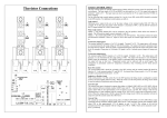
Twelve Pulse Connections
•
•
•
•
•
•
•
•
•
Power Supplies
Half and Fully controlled Rectifiers
AC Motor Control
DC Motor Control
Soft Starters
Heater Controllers
Induction Generator
AC Voltage Regulation
Three Phase Transformer Control
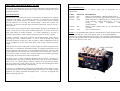
Additional Firing boards can be configured to
trigger paralleled SCR’s for very high current
applications or to provide a twelve pulse driver for
smooth DC control
Key Features
Thyristors require a high initial gate current pulse
and comparatively wide sustaining pulses to ensure
reliable firing, particularly at small phase control
angles. The FC36M provides the following firing
specifications
• Gate Drive: Picket Fence with a PRF of 25Khz
an initial firing pulse of; 8 volts open circuit. 800 mA
into 1 Ohm, and sustaining pulses 400mA into 1 Ohm
per output. The sustaining pulses are 20 uS Wide.
• High output initial triggering pulses
• Gate isolation to 3500 V rms.
• Adjustable Soft start and soft start times
• Selectable hard start and hard stop
• 50/60 Hz operation auto selection
• Remote Logic input for control in noisy environment 524 V dc
• Two analogue control inputs 0-5 V dc and 4-20mA
• Current control input 0-100 mV
• Over-current limit trip (Latching)
• Adjustable ramp control 0-30 seconds
• Pre-selectable or automatic Phase Angle to Burst Fire
control
• Switchable Phase reversal
• Selectable Inductive or Resistive load setting
• Selectable timing delay for use as a twelve pulse driver
• High immunity to mains voltage distortions
• Complete with integral phasing and supply transformer.
OPERATING INSTRUCTIONS
APPLICATIONS
The firing circuit responds to voltage or milliamp current signals to produce six 60° spaced high current
thyristor gate pulses. Additional boards can be configured for high current parallel gating of additional
thyristors and for twelve pulse converters (rectifiers).
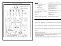
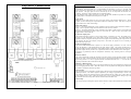
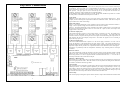
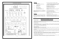
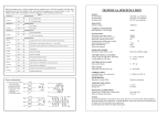
CONNECTIONS
The Gate and Cathode outputs have 6.3mm blade terminals. All other connections are made with captive
screw and leaf terminal blocks. 0.25mm header connections are provided to connect firing boards for
paralleled thyristor drive or 12 pulse configuration.
Note: - J1 Jumper reverses pulse transformer outputs.
LED INDICATION
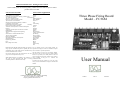
Three LED’s are used for status and fault indication. The LED1 (green) is situated in the centre of the board
and illuminates when the 5 volts dc supply is present.
When SW2 position No 2 is ON, LED 2 (red) will illuminate when the LIMIT input has reached the level set
by (I SET)
LED 2 and LED 3 (orange) will alternately flash on a 1 second timebase when the LIMIT input exceeded the
value set by VR1 (I TRIP). The FC36M will shut down and will stay latched in this statue until the
microprocessor is powered down or reset.
Under normal conditions LED 3 is used to indicate the output status. In phase Angle mode, when the
control signal is increased, so does the brightness of LED 3. In Burst Fire mode LED 3 will pulse on a one
second timebase with a variable mark space (on-off) ratio determined by the control signal.
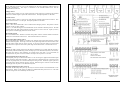
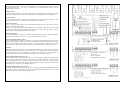
ANALOGUE CONTROL INPUTS
For the following analogue control options the 6 way DIL switch (SW2) should have position No.1 switched
to the ON position. For additional control options see table A on page 6 of this manual.
10
3