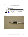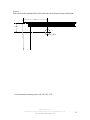
1
User’s Manual
For the
SHORE POWER CONNECTION MONITOR
MODEL 9151
Table of Contents:
Product Description .................................................................................................... 3
Installation................................................................................................................... 4
Optional Remote Alarm Installation........................................................................... 7
Operator Test .............................................................................................................. 8
Alarms......................................................................................................................... 9
Figures....................................................................................................................... 10
Shurite Marine Systems
Telephone (203) 481-5721 • Facsimile (203) 481-8937 • [email protected]
www.primetechnology.com
2
Product Description
The shore power connection monitor or ShIP constantly monitors the temperature of the
on-board shore power inlet contacts and the wiring to it. When an overheated condition is
detected the monitor will disconnect power to the vessel from shore power and sound an
audible alarm to notify ships personnel. Ship’s personnel can then determine what action
to take to prevent further damage to the vessel.
The shore power connection monitor provides the following features:
•
The temperature monitor periodically performs a self-test and advances the green
TEMPERATURE SCANNING LEDs to notify personnel the unit is operating
correctly.
•
A green SHORE POWER LED indicates shore power is present.
•
A red REVERSE POLARITY LED indicates a reverse polarity input power
connection.
•
A yellow OVER TEMPERATURE LED indicates an over temperature condition
exists on the shore power connection.
•
The audible alarm can be manually silenced from the front panel.
•
A remote alarm connection with a single set of normally open and normally
closed contacts.
•
If an overheated condition occurs, the audible alarm will sound for a maximum of
five (5) minutes and then turn off to avoid a prolonged disturbance to neighboring
vessels. The red ALARM TRIPPED LED will remain on until the user actively
resets the unit.
•
Depressing the TEST push button will perform a built in test which will simulate
an over temperature condition and trip the circuit breaker.
Shurite Marine Systems
Telephone (203) 481-5721 • Facsimile (203) 481-8937 • [email protected]
www.primetechnology.com
3
Installation
Warning – Hazardous voltages may be present, a licensed electrician should perform
the shore power connection monitor installation.
________________________________________________________________________
1. Disconnect all shore power from the vessel and turn off all on board generators.
2. Determine the location for mounting the enclosure. This location must be on a
vertical wall. This device has not been approved as an ignition protection device.
It must not be located in an area where flammable fuels are present.
See ABYC E-11 AC and DC Electrical Systems on Boats section 11.5.1.3 for
recommended spaces.
The enclosure should be mounted between the shore power inlet connector and
the AC power distribution panel somewhere along the AC power cable path.
3. ABYC E-11 AC and DC Electrical Systems on Boats section 11.12.2.9.3. states:
“ If the location of the main shore power disconnect circuit breaker is in excess of
10 feet (three meters) from the shore power inlet or the electrical attachment
point of a permanently installed shore power cord, additional fuses or circuit
breakers shall be provided within 10 feet (three meters) of the inlet or attachment
point to the electrical system of the boat. Measurement is made along the
conductors.”
Mounting the ShIP enclosure within 10’ of the inlet connector will satisfy this
requirement.
4. The enclosure has two internal terminal blocks for the AC power cable, spaced
five (5) inches apart (See figure 1). This will allow the installer to cut the existing
AC power cable, strip the cable wires, and connect the enclosure in series with the
cut cable. Installing the enclosure in this manner will eliminate the time and
expense of running a new AC power cable from either the shore power inlet
connector and the enclosure, or the AC power distribution panel and the
enclosure.
If this is physically not possible, the installer must make a decision whether it is
more economical to run a new AC power cable from the enclosure to the AC
distribution panel or to the shore power inlet connector.
5. Remove the four plastic screws from the monitor enclosure and carefully lift off
the front panel. (See figure 1) There are three signal connectors that can be
removed from the printed circuit board by squeezing the locking tabs on the
Shurite Marine Systems
Telephone (203) 481-5721 • Facsimile (203) 481-8937 • [email protected]
www.primetechnology.com
4
connector and pulling on the connector. During installation, it is not necessary to
completely detach the front panel by disconnecting the power wires, provided
caution is used so as not to apply unnecessary pressure on it.
6. Included in the Hardware Kit are two types of cable glands, one for a round AC
power cable and one for a rectangular AC power cable. Determine which type of
AC power cable is used on the vessel and install one on the left hand side of the
enclosure and one on the right. There are two different size locknuts also supplied
in the Hardware Kit, use the locking nuts to securely fasten the cable glands to the
enclosure.
7. Install the ShIP enclosure on a vertical bulkhead. Fasten the box using four screws
in the corner holes (See black arrows in Fig. 1) under the front panel screws to
prevent the box from coming off the bulkhead while under way.
8. The ShIP receives power from the shore power connection made to the marina.
The ShIP enclosure may be mounted on either the port or starboard side of the
vessel; either forward or aft of the shore power inlet connector. The power cable
from the shore power inlet connector may enter either on the left side or right side
of the enclosure. It is important to connect the ShIP internal AC wiring to the
proper terminal block (left or right) to maintain power to the ShIP if the circuit
breaker is tripped. The ShIP comes pre-wired from the factory for a right hand
power entry. That is, the power from the shore enters the right hand side of the
enclosure.
In the case where the power enters the left hand side the installer must remove the
black wire on the right hand terminal block labeled LINE and remove the black
wire on the left hand terminal block labeled LOAD. Then connect the black wire
labeled LINE to the left hand terminal block and connect the black wire labeled
LOAD to the right hand terminal block.
9. Route the AC power cable through the cable clamp on the left hand side of the
enclosure to the left hand terminal block and connect the hot black wire to the
open terminal block connection across from the black wire, neutral white wire to
the open terminal block connection across from the white wire, and ground green
wire green to the open terminal block connection across from the green wire.
Route the AC power cable through the cable clamp on the right hand side of the
enclosure to the right hand terminal block and connect the wires to the open
terminal block connections as above.
Tighten both cable gland-clamping nuts to strain relief the AC power cables on
both sides on the enclosure.
Make sure all screws on the terminal blocks are tight.
Shurite Marine Systems
Telephone (203) 481-5721 • Facsimile (203) 481-8937 • [email protected]
www.primetechnology.com
5
10. Clean out any strands of wire remaining in the enclosure after installing wires.
11. Locate and remove the shore power inlet connector and disconnect the existing
vessel’s AC power cable from the inlet connector. Inspect the shore power inlet
connector for signs of corrosion, melted plastic, or discolored terminals caused by
overheating. Replace the inlet connector if it has been damaged. Inspect the wires
of the vessel’s AC power cable for signs of melted insulation or discolored wire
due to overheating. The wires may have to be cut back and stripped or replaced
before proceeding.
12. Position one of the sensors 3/8” from the stripped edge of the hot black wire of
the AC cable (see figure 2) and hold it there. Slide the shrink tubing supplied in
the Hardware Kit over the sensor and the wire. Use a heat gun to shrink the tubing
evenly over the sensor and wire (see figure 3). The sensor assembly should be
firmly fastened to the wire. Use a tywrap to secure the wires of the sensor to the
wire to prevent breaking the sensor wires while handling the AC wires.
13. Repeat the previous step for the neutral white wire of the AC cable using the other
sensor.
14. Reconnect the wires to the shore power inlet connector; hot black wire to black
terminal, neutral white wire to white terminal, and ground green wire to green
terminal. Reinstall the shore power inlet connector.
15. Route the other end of the sensor signal cable to the ShIP enclosure location. Feed
the sensor cable through the small cable clamp on the left hand side of the
enclosure. Cut the sensor cable 2” to 3” longer than it takes to reach J2 on the
PCB (shown by the white arrow in figure 1). Strip the ends of the red and black
pair and insert them into J2 positions 1 and 2 and tighten the screws; polarity
doesn’t matter. Strip the ends of the white and black pair and insert them into J2
positions 3 and 4 and tighten the screws.
16. Clean out any strands of wire remaining in the enclosure after installing wires.
17. Reconnect the three front panel signal connectors to the printed circuit board,
replace the front cover and tighten the four plastic screws.
18. Reconnect the shore power to the vessel. On the shore power monitor front panel
the green shore power LED should be on and the green temperature scanning
LEDs in the shape of a wave should sequentially turn on. (If the green shore
power LED is not on, disconnect the shore power and check the connections made
in the previous steps.)
19. This concludes the installation.
Shurite Marine Systems
Telephone (203) 481-5721 • Facsimile (203) 481-8937 • [email protected]
www.primetechnology.com
6
Optional Remote Alarm Installation
The ShIP 110 provides a normally open and normally closed relay contact for an isolated
remote alarm feature. These contacts are rated for 115 VAC at 10 Amps. The installer
needs only to wire in the remote alarm to either J5-1 & J5-2 for a normally closed alarm
or J5-1 & J5-3 for a normally open alarm. The ShIP will energize the remote alarm relay
changing the condition of the contact closures for an alarm condition. Note: Hardware is
provided for an alarm cable diameter between 0.20” to 0.32”. If the remote alarm cable is
of a different size the installer must provide a suitable water resistant cable gland
otherwise the warrantee will be void.
Warning – Hazardous voltages may be present, a licensed electrician should perform
the shore power connection remote alarm installation.
________________________________________________________________________
1. Disconnect all shore power from the vessel and turn off all on board generators.
2. Drill an 11/16” hole on the right hand side of the enclosure using figure 4 as a
guide.
3. Install the 3/8” cable gland and locking nut provided in the Hardware Kit. This
cable gland will accept and seal a 0.20” to 0.32” diameter cable.
4. Feed the remote alarm cable through the cable gland and cut the sensor cable 2 to
3” longer than it takes to reach J5 on the printed circuit board. Strip the ends of
the remote alarm cable and insert them into J5 positions 1 and 2 for a normally
closed alarm or J5-1 & J5-3 for a normally open alarm and tighten the screws.
5. Clean out any strands of wire remaining in the enclosure after installing wires.
6. Tighten the cable gland-clamping nut to strain relief the remote alarm cable.
7. Reconnect the shore power to the vessel.
8. Perform the Operator Test described in the next section to test the remote alarm.
Shurite Marine Systems
Telephone (203) 481-5721 • Facsimile (203) 481-8937 • [email protected]
www.primetechnology.com
7
Operator Test
Warning – To prevent damage to air conditioning compressors and other equipment
the operator should wait a few minutes before turning the breaker back on. Read the
air conditioner users manual for recommended times.
________________________________________________________________________
A simple test can be performed to check for proper operation of the monitor. The
operator should press and hold the TEST push button for at least 2 seconds. The circuit
breaker will trip, and the audible alarm and the red ALARM TRIPPED LED will stay on
as long as the push button is depressed. Releasing the push button will turn off the
audible alarm and the green TEMPERATURE SCANNING LEDs will resume scanning
indicating the monitor has resumed checking for an over temperature condition. The
operator must manually reset the circuit breaker.
Shurite Marine Systems
Telephone (203) 481-5721 • Facsimile (203) 481-8937 • [email protected]
www.primetechnology.com
8
Alarms
If an actual alarm occurs or upon returning to the vessel the monitor is in an alarm
condition, the red ALARM TRIPPED LED is on and the main switch is tripped, the
following steps are recommended:
1. MUTE the audible alarm (if necessary), depress and hold the mute button for at
least 2 seconds.
2. Turn off the shore power at the dock and check the following:
•
Check the shore power inlet connector for corrosion and loose connections
and repair if necessary.
•
Check the shore power connector from the marina for corrosion and loose
connections, and repair if necessary.
•
If the yellow OVER TEMPERATURE LED is still on, the inlet connector
is too hot and must be allowed to cool before the alarm can be cleared.
•
After the problem is corrected depress and hold the ALARM CLEAR
push button for at least 2 seconds, and manually reset the circuit breaker.
If only the red ALARM TRIPPED LED is on and the scanning LEDs are not scanning
the monitor has detected a circuit problem and must be serviced to ensure proper
operation. It could be one of the following.
• Sensor cable open
• Sensor cable short
• Circuit failure on the PCB
If only the main switch is tripped there is an overload condition somewhere on the vessel.
Shurite Marine Systems
Telephone (203) 481-5721 • Facsimile (203) 481-8937 • [email protected]
www.primetechnology.com
9
Figures
Figure 1
Shore power connector monitor box with front panel removed.
Shurite Marine Systems
Telephone (203) 481-5721 • Facsimile (203) 481-8937 • [email protected]
www.primetechnology.com
10
Figure 2
Temperature Sensor Assembly
Thermistor
Tywrap
Current Carrying
C d t
3/8 "
Shrink Tubing
Figure 3
Shurite Marine Systems
Telephone (203) 481-5721 • Facsimile (203) 481-8937 • [email protected]
www.primetechnology.com
11
Figure 4
Drill a hole on the right hand side of the enclosure for the Remote Alarm cable gland.
2.25"
1.125"
.6875"
For claims under warranty please call (203) 481-5721.
Shurite Marine Systems
Telephone (203) 481-5721 • Facsimile (203) 481-8937 • [email protected]
www.primetechnology.com
12