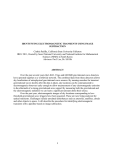
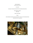
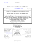
1
University of Glasgow, IREU 2014 Alyssa Conway The properties of very thin silica fibers for use in precision
measurement experiments.
Alyssa Conway
Department of Physics, Lake Forest College, 555 N. Sheridan Rd, Lake Forest IL, 60093,
USA.
Summary
To directly detect gravitational waves using ground-based interferometers,
enormous experimental efforts to minimize noise are underway. Suspension thermal
noise, the main noise source for low frequencies, can be minimized using multi-staged
pendulum suspension systems of quasi-monolithic fused silica. Such fibers of 380 to 400
micrometer diameters have been pulled at the University of Glasgow using a 120 W, 10.6
micrometer wavelength CO2 laser fused silica fiber pulling machine, and similar fibers
have been used in GEO600 and aLIGO. Work is in the early stages at the University of
Glasgow to create a micro fiber puller, which would create one to twenty micrometer
diameter fused silica fibers with lengths from five to fifty millimeter pulled from one to
two millimeter fused silica stock using a similar CO2 laser setup. These ultra thin fibers
could be used in small prototypes like the 10 m prototype at AEI to test and minimize
shot noise and radiation pressure noise. The author wrote the LabVIEW control programs
for the motorized stages that will pull the silica in the new machine, and machining and
assembly of the micro fiber puller are ongoing.
1 University of Glasgow, IREU 2014 Alyssa Conway I. INTRODUCTION
Gravitational waves, as predicted by Albert Einstein’s Theory of General
Relativity in 1916, are ripples in the curvature of spacetime. Although gravitational
waves have been indirectly detected, present research focuses on direct detection.
Sources for direct detection include violent astronomical phenomena, binary star systems,
and black holes. Currently, ground-based interferometry is an important branch in direct
detection attempts, with great experimental difficulties arising from the small amplitude
change to be detected at very low frequencies amongst many noise sources. In order to
reduce seismic noise and isolate mirrors in interferometers, multi-staged pendulum
suspension systems are used. Then, thermal noise from the suspension becomes the
primary noise source at low (5-50 Hz) frequencies, as shown in Figure 1.
Figure 1: GEO600 theoretical noise sources (via Cumming Thesis, Figure 1.8, pg 25)
2 University of Glasgow, IREU 2014 Alyssa Conway As a result, producing low thermal noise suspensions is an important subfield in
current gravitational wave research. The lowest loss, and lowest thermal noise, is
achieved if the entire system is monolithic; that is if the system were made out of the
same piece of material - the suspension, the mirror, and the connections between them.
One low loss, high dilution material that has been used in quasi-monolithic suspension
systems for GEO600 and aLIGO is silica. Present research in this paper focuses on
reliably producing fused silica suspension fibers for use in precision measurement
experiments. Previous efforts have used hydrogen-oxygen flames to pull silica fibers;
however, particulates introduced from byproducts of this method can introduce defects
into the surface of the fiber and increase noise. In addition, uneven heating can induce
cracks in the silica, which further increase thermal noise. Thus, this method has
been replaced by the use of a CO2 laser for more even, reliable heating with a better
system of feedback from the use of a laser.
The Institute for Gravitational Research (IGR) at the University of Glasgow in
Scotland developed, created, and tested a CO2 laser fused silica fiber pulling machine
capable of creating fibers that meet strength, thermal noise, and dimensional tolerance
requirements for aLIGO generation gravitational wave detector mirror suspensions
(Heptonstall, et al). The resulting fibers are 380 micrometers in diameter at their thinnest
central section (Heptonstall, et al). Figure 2 shows similar fibers with diameters of 400
micrometers from the draft by Cumming, et al. Current efforts focus on creating a microfiber pulling machine that will produce fibers one to twenty micrometers in diameter.
3 University of Glasgow, IREU 2014 Alyssa Conway Figure 2: Advanced LIGO fiber end pulled from 3 mm stock (Cumming, A. et al. Draft,
Figure 2).
II. MOTIVATION
The CO2 laser micro pulling machine currently in development at the University
of Glasgow in Scotland aims to produce thin silica fibers from one to twenty microns in
diameter. These thin fibers can be used in experiments investigating quantum noise
sensitivities, like the AEI or the small interferometer in Glasgow; these thin fibers have
industrial applications as well.
A. AEI & IGR
Further increasing sensitivities of interferometric techniques is clearly a large
focus among current research. Several interferometric prototype facilities exist with aims
to further increase these sensitivities by exploring noise sources at detection extremes.
For instance, the Albert Einstein Institute in Hannover, Germany is currently
constructing the AEI 10 m prototype interferometer facility. This prototype aims to,
among other things, explore the extremes of shot noise and radiation pressure noise (as
4 University of Glasgow, IREU 2014 Alyssa Conway shown in Figure 3) for future improvements to larger interferometer facilities and
techniques. The AEI prototype will use 100 g test masses with multi-staged pendulum
suspensions in a 10 m arm Michelson interferometer. The lowest stage for the small, 50
mm diameter interferometer mirrors will employ a monolithic suspension of 20
micrometer diameter, thin fused silica fibers (Westphal, et al).
Figure 3: Noise spectrum of AEI 10 m prototype. Photon shot noise dominates for
frequencies greater than or equal to 200 Hz, while quantum radiation pressure noise dominates
for frequencies below 200 Hz (via Westphal, et al. Figure 5).
Another small prototype exists in the IGR at the University of Glasgow in
Scotland that also aims to reduce quantum noise. This interferometer will use one-gram
mirrors suspended on one-micron thin silica fibers.
B. Industrial applications
5 University of Glasgow, IREU 2014 Alyssa Conway Many industries that require reliable, low loss, thermally stable optical fibers can
also use the silica fibers pulled from the new machine and the new pulling techniques
utilized. One such application would be in oil or gas sensing (OFS).
III. SETUP & DESIGN
A. CO2 laser fused silica fiber puller
The Institute for Gravitational Research (IGR) at the University of Glasgow in
Scotland developed, created, and tested a CO2 laser-based fused silica fiber pulling
machine capable of creating fibers that meet strength, thermal noise, and dimensional
tolerance requirements for aLIGO generation gravitational wave detector mirror
suspensions (Heptonstall, et al). The resulting fibers are 380 micrometers in diameter at
their thinnest central section (Heptonstall, et al).
The machine employs a 120 W CO2 laser that produces infrared radiation at a
wavelength of 10.6 micrometers, which is directed with a Zinc-Selenium telescope, two
gold-coated conical mirrors, and a rotating 45-degree gold mirror to focus at a fixed point
along the silica fiber. A meter-tall, double leadscrew tower, on which two carriages run,
is mounted vertically. Each carriage is driven independently by a DC servo motor that is
controlled by a LabVIEW control program (Cumming Thesis, 76). The silica fiber is
clamped to one fixed end below, and to a moving clamp on the upper moving carriage;
the bottom conical mirror is also fixed, while the upper conical mirror is mounted on the
lower moving carriage. The fiber pulling machine and a close-up of the mirrors directing
the laser are diagramed in Figures 4 and 5 from the paper by Heptonstall, et al; a
photograph of the original laser setup from the same paper is also included as Figure 6. A
6 University of Glasgow, IREU 2014 Alyssa Conway more recent (between 2008 and 2014) photograph of the fiber puller at the University of
Glasgow is also included in Figures 7.
Figure 4: SOLIDWORKS rendering of the fiber pulling machine in cylindrical fiber
configuration (via Heptonstall, et al. Figure 4).
7 University of Glasgow, IREU 2014 Alyssa Conway Figure 5: SOLIDWORKS rendered drawing of the laser beam delivery for cylindrical
fiber production (via Heptonstall, et al. Figure 5).
8 University of Glasgow, IREU 2014 Alyssa Conway Figure 6: Photograph of fiber puller optical setup. CO2 laser delivered through articulated
arm, ZnSe output telescope, and a pair of mirror galvanometers (via Heptonstall, et al. Figure 9).
9 University of Glasgow, IREU 2014 Alyssa Conway Figure 7: Photograph of fiber puller at the University of Glasgow (courtesy of Dr Alan
Cumming and Russell Jones).
When pulling a cylindrically shaped fiber, the lower carriage with the upper
conical mirror can move up slowly to focus the laser and heat different positions on the
10 University of Glasgow, IREU 2014 Alyssa Conway silica fiber as the upper carriage pulls the upper end of the silica fiber up. This pulling
process is viewable in action via the attached video, courtesy of Dr Alan Cumming and
the University of Glasgow.
B. Micro-puller plans
The micro-puller is currently in development. The general setup will be similar to
that of the puller discussed in section III.A, but the new machine will pull one to twenty
micrometer diameter thin fibers.
The machine will employ a 120 W CO2 laser with wavelength 10.6 micrometers.
The laser will be directed by the same optical arrangement described in section III.A,
except instead of a rotating 45-degree gold mirror, a stationary 45-degree gold coated
cone will be used to direct the beam to the gold-coated conical mirrors, which will
ultimately focus the beam at a point on the silica fiber.
Instead of two carriages mounted on the same double leadscrew tower, two
separate stages will be mounted as shown in Figure 8. The Newport IMS-400LM stage
has a range of 400 mm, a maximum velocity of 500 mm/s, and a maximum acceleration
of 26 000 mm/s², and is driven by a three-phase synchronous iron core linear motor. The
ThorLabs MTS50-Z8 motorized translation stage has a range of 50 mm, a maximum
velocity of 2.4 mm/s, and a maximum acceleration of 4.5 mm/s², and runs using a dual
set of linear rails with continuously recirculating ball bearings. The motion of the
Newport and ThorLabs stages are controlled by a LabVIEW program written by the
author; additional information on the program is provided in section V. Clamps will be
11 University of Glasgow, IREU 2014 Alyssa Conway mounted on each stage, attaching one end of the silica fiber to each stage, while the
conical mirrors remain stationary.
Figure 8: CAD rendering of micro fiber pulling machine, courtesy of Dr Liam Cunningham and
Russell Jones.
The speed of the pull with this setup will be much greater than that of the previous
fiber puller, and the starting silica stock will be smaller to produce even thinner, shorter
fibers. As a result, moving the mirrors to redirect the beam along different positions on
the silica stock may not be necessary, hence the conical mirrors are currently drawn as
stationary in the most recent diagrams (Figures 9 and 10). In addition, contrary to initial
12 University of Glasgow, IREU 2014 Alyssa Conway plans, the Newport stage must be mounted horizontally according to the manufacturer.
Consequently, a new model of the machine was created that is essentially the previous
model rotated on its side so that the Newport stage can run horizontally; all of the
diagrams (Figures 8, 9, and 10) included here are from the most recent (as of August
2014) CAD renderings from Dr Liam Cunningham. Again, because the pull will be fairly
quick, concerns over gravity’s influence causing any drooping in the fiber are minimal at
this time. Furthermore, if the Newport stage is moving quickly enough, and the lower
motor (Thorlabs) stage moves so slowly in comparison, the Thorlabs stage may even
remain stationary during the pull; (the option to move each stage independently is
available in the current control program).
Figure 9: CAD rendering of micro fiber pulling machine, courtesy of Dr Liam
Cunningham and Russell Jones.
13 University of Glasgow, IREU 2014 Alyssa Conway Figure 10: CAD rendering of micro fiber pulling machine, courtesy of Dr Liam
Cunningham and Russell Jones.
IV. EQUIPMENT
A. Newport
A.1
Connection
The Newport IMS-400LM motorized stage is controlled by the Newport XPS-
DRV02 Driver, which interfaces with the subVIs used from Newport-built libraries
(grouped into the folder called XPS-Q8) that have been loaded into this version of
LabVIEW. The connections among LabVIEW, the XPS controller, and the stage require
the IP Address (currently 192.168.0.254), the Group Name (Group1), and the Positioner
Name (Group1.Pos). The Newport Connect & Initialize & Home subvi shows the
14 University of Glasgow, IREU 2014 Alyssa Conway required sequence necessary to connect the stage and enable the ready state (see also,
State diagram of the XPS controller on page 68 of XPS User’s Manual or Figure 11
here), from which the desired motion states can be entered.
Figure 11: State diagram of the XPS controller (XPS User’s Manual, pg 68).
A.2
Motion
The Newport stage can move by position, either from the current position to the
desired destination (absolute move) or by a defined increment (relative move), all
following the SGamma set parameters as explained in the next section (XPS User’s
Manual, 79). Or, the Newport stage can undergo jog motion, which is defined by velocity
15 University of Glasgow, IREU 2014 Alyssa Conway and acceleration (which can be changed during motion), and for which the end of motion
is defined by setting the velocity to zero (XPS User’s Manual, 83).
The IMS-400LM travels along positions from -200 mm to 200 mm at velocities
from -500 mm/s to 500 mm/s (excluding 0 mm/s) with accelerations from 0.0001 mm/s²
to 26000 mm/s². There are hardware limit switches built into the stage that prevent it
from moving past its range regardless of the software controls in place.
A.3
Motion profiler
In order to reduce mechanical resonance caused by abrupt changes in the moving
system, the XPS controller uses an SGamma motion profile (as the example in Figure 12
shows) instead of a classical trapezoidal velocity profile (XPS User’s Manual, 71). Each
positioner has an associated motion/trajectory profiler and a PID corrector (XPS User’s
Manual, 169-170); in this case,
Stage: IMS400LM
Driver: XPS-DRV02
MotorDriverInterface: AnalogAcceleration
CorrectorType: PIDFFAcceleration.
16 University of Glasgow, IREU 2014 Alyssa Conway Figure 12: SGamma motion profile for maximum velocity 0.8 units/s, maximum acceleration 12
units/s2, minimum jerk time 0.004 s, maximum jerk time 0.04 s.
A.3.1 Tuning
While operating the stage within its recommended software limits (maximum
speed with no load = 500 mm/s, maximum acceleration with no load = 26 mm/s²), the
standard Newport settings for the PID parameters in the stage initialization (stage.ini)
files should work adequately. If performance optimization is still necessary, or if
following errors are detected, the user can automatically or manually tune the PID
parameters using LabVIEW or the online XPS interface.
Instructions for tuning are on pages 177-179 in the XPS User’s Manual. To access
the PID parameters individually through LabVIEW subVIs, follow palettes XPS-Q8 ->
17 University of Glasgow, IREU 2014 Alyssa Conway Positioner -> Positioner Corrector PIDFF Acceleration Set. Alternatively, the stages.ini
file can be accessed directly through the online XPS interface.
Once connected online (see the Quick Start Guide for connection instructions),
enter the IP address of the connection (presently, 192.168.0.254) for the url, and enter or
select Administrator for the Name, Password, and Rights fields. Select STAGE from the
top menu, then Modify from the submenu, then select IMS400LM@XPS-DRV02, and
press Modify. Change the necessary parameters, press Save and then Reboot; after about
20 seconds the XPS driver should have beeped twice if it correctly reset. Alternatively,
select TUNING from the top menu, then select Group1.Pos from the dropdown menu to
temporarily set corrector parameters or use the automatic tuning.
A.3.2 Recommended default SGamma settings
Velocity = 5.000 000 E+2 units/sec = 500.000 mm/s
Acceleration = 2.600 000 E+4 units/sec/sec = 26 000.000 mm/s/s
Minimum Jerk Time = 4.000 000 E-2 seconds = 0.040 000 00 s
Maximum Jerk Time = 4.000 000 E-2 seconds = 0.040 000 00 s
B. ThorLabs
B.1
Connection
The ThorLabs MTS50-Z8 motorized stage is controlled by the ThorLabs APT-DC
Servo Controller, TDC001, which interfaces with the ActiveX plugin in LabVIEW such
that property nodes control the motion and settings of the stage. The connection requires
the serial numbers for the stage (417192) and the controller (83823439).
18 University of Glasgow, IREU 2014 B.2
Alyssa Conway Motion
The ThorLabs stage moves according to a trapezoidal motion profile for which
the user sets minimum and maximum velocities and the acceleration. The stage can move
by position, either from the current position to the desired destination (absolute move) or
by a defined increment (relative move). Or, the stage can undergo jog motion, for which a
signal is sent to the stage to initiate motion that is controlled by the motion profile and the
extrema parameters set by the user, until another signal is sent to stop the stage.
The ThorLabs stage travels along positions -1.000 mm to 49.000 mm at velocities
in range from 0 mm/s to 2.4 mm/s, and accelerations from 0.0001 mm/s² to 4.500 mm/s².
The stage can travel in either direction, which is set by a switch (not by entering negative
speeds, which will return an error). The ThorLabs stage has hardware limit switches that
stop the motion from continuing past the range limits regardless of the software settings.
V. DUAL MOTOR CONTROL PROGRAM
The control program was written using National Instruments LabVIEW 2013 SP1
(64-bit). LabVIEW is a data-flow oriented, C++ programming language with a graphical
interface especially useful for connecting and controlling machinery. The program code
is created on the block diagram, which includes subVIs (methods) and control structures
(loops, conditionals) that have inputs and outputs wired together like an electrical circuit
that executes according to what data is available (Cumming Thesis, 224). The user
interacts with the front panel, which includes controls (buttons, number inputs) and
indicators (number outputs, graphs, flashing lights).
19 University of Glasgow, IREU 2014 Alyssa Conway The VI control program, called Short Fiber Puller Acceleration & Time File
Summer 2014, controls the movement of the Newport and ThorLabs stages, and contains
enough flexibility to someday include control of the laser as well. Figure 13 below shows
the general progression of the block diagram: First, both stages are connected and select
controls are made visible on the front panel. Then the VI runs in a state machine format
until the user or an error ends the VI, and the stages disconnect. More specifically, Figure
14 shows the different paths that can be taken in the state machine; the user can choose
once the stages are connected whether to control only one of the stages or to control both
simultaneously. In addition, Figure 15 shows the block diagram in its default Idle state,
and Figure 16 shows the front panel for user interface. Additional screen captures of the
other states are included in Appendix A, along with a list of all the subVIs necessary for
the VI to run.
Figure 13: Dual motor control block diagram schematic.
20 University of Glasgow, IREU 2014 Alyssa Conway Figure 14: Progression of states in dual motor control program, schematic diagram; can be
chosen for Newport stage only, for ThorLabs stage only, or for both stages simultaneously once
connected.
21 University of Glasgow, IREU 2014 Alyssa Conway Figure 15: Block diagram of micro fiber dual motor control program in its default Idle state.
22 University of Glasgow, IREU 2014 Alyssa Conway Figure 16: Front panel of micro fiber dual motor control program.
A. Newport jog control
A.1 File entry
The VI prompts the user for a pulling file, which should include the velocity,
acceleration, and time parameters to control the movement of the Newport stage only; by
extension, the cumulative amount of time the Newport stage moves is approximately the
same amount of time the ThorLabs stage moves, although its movement and speed are set
separately.
The pulling file should be a text file with three columns:
1st=Velocity (mm/s), 2nd=Acceleration (mm/s²), 3rd=Time (ms).
23 University of Glasgow, IREU 2014 Alyssa Conway Text files should have only numbers and be tab delimited (copy and paste from
excel works fine).
For corresponding rows (indices), the Newport stage will move at the constant
velocity for the corresponding time, and will accelerate from the previous velocity to
reach the new velocity using the corresponding acceleration.
For example, consider two rows from some file (labeled for convenience),
(Vel) (Accl)
(Time)
300
2500
2000
(row 5)
400
5000
1000
(row 6)
When executing row 6, the Newport stage will accelerate at 5000 mm/s² from an
initial velocity 300 mm/s to reach the velocity of 400 mm/s, which should take about
timeacc = (vf-v0)/a = 20 ms. Then the stage will move at the constant velocity 400 mm/s
for timevel = 1000 ms. As a result, the stage will move approximately x = vf*timevel +
0.5*a*timeacc^2 = 400*1 + 0.5*5000*0.02^2 = 400 mm + 1 mm = 401 mm.
This example, however, would move the Newport stage beyond its 400 mm
range. Thus, the Check File state checks that any such errors are caught, and does not
allow the user to initiate jog mode until the file and current parameters of the stage will
not cause errors (see section V.C for more on error checking).
A.2 Distance calculation
24 University of Glasgow, IREU 2014 Alyssa Conway It is important to note that this distance calculation only agrees with the actual
distance travelled by the Newport stage on the order of one millimeter. However, the
repeatability of the stage under identical settings (for each parameter and pulling set) is
on the order of tens of microns. In other words, for each pulling file or parameter set, the
stage travels consistently to the same ending position within about 0.04 mm. In summary,
motion is repeatable to an accuracy of approximately 1 mm, and to a precision of about
0.04 mm.
A.3 Stop considerations in file entry
In order to stop the Newport stage immediately or as close to the desired
time/distance as possible, the user should include zero as the last velocity in the jog
control pulling file. If the stage is moving at fairly large velocities, even a small time
delay from transitioning states in the LabVIEW state machine could cause a significant
change in ending position. For example, if the velocity is 250 mm/s, just half of its
maximum, the stage could move 2.5 mm in just 10 ms. Clearly, this distance in nonnegligible if our aim is on the order of microns or tens of microns of precision.
If the user would rather not include the immediate stop of the Newport stage in
the pulling file (for timing reasons, see section V.B.2), this extra time should be
considered. Note that the time delay introduced from these programmatic transitions may
or may not be consistent between runs of the VI. If the delay is consistent, the user need
merely to keep the change in accuracy in mind. If the delay is inconsistent, which the
programmer believes is more likely if only due to more possibilities of programmatic
hang-ups during the state-to-state transition, then some degree of precision would be
25 University of Glasgow, IREU 2014 Alyssa Conway sacrificed, and this amount would vary depending on the velocity. Thus, the simpler
solution remains that the zero velocity be included in the pulling file to immediately stop
the Newport stage.
B. Newport & ThorLabs & laser timing control
B.1 Start
The Wait & Start Jog state waits for the Laser Ready indicator to be true, then
waits for the time delay, if entered. Then the VI transitions to the Pulling state. Here, the
ThorLabs stage motion can be delayed some time after the Newport stage begins motion,
or the other way around, or they can start at nearly the same time (with the Newport stage
starting just before the TL stage, on the order of milliseconds).
To start the Newport stage then the TL stage afterward, the user can simply enter
some millisecond time in the Delay TL Start (ms) After Newport control. If jog motion
begins for the Newport stage without errors, the VI will wait for that time delay and then
initiate the ThorLabs stage to begin its jog motion. However, this time delay must be less
than the time the Newport stage is set to move during its first set velocity.
It is possible, but seems unnecessary, to start the ThorLabs stage before the
Newport stage. To do so, set the Delay TL Start (ms) After Newport control to zero, and
in the pull file set the first velocity to zero, with the time set for the length of the advance.
B.2 Stop
Presently, if (as recommended) the last velocity in the pulling file is zero, the
upper motor will stop first, even before the Stop state is entered; and in the Stop state, the
26 University of Glasgow, IREU 2014 Alyssa Conway zero velocity is fed again to the Newport stage (in most cases this will do nothing, but it
will stop the stage in case an error occurred), and then the ThorLabs stage receives the
stop command as well.
However, if the user wishes to control the stopping of the Newport stage in
relation to the laser or ThorLabs stage differently, the last velocity can be non-zero. In
this case, the user must explicitly allow the file to be used (a dialogue box will appear).
Then the user can introduce delays between stopping the stages and laser. Note, then, the
time to transition to the stop case would need to be considered (as mentioned in V.A.3),
and both stages would move farther than calculated.
Furthermore, if any delays are introduced, the stages could move farther than their
calculated displacements. Thus, any additional time (if larger than 10s or 100s of
milliseconds, depending on the speed of the stage) should be added into the file check
state and subVIs. At the moment, both stop subVIs are in the same case in the state
machine since stopping both stages at the same time (or as close to it as possible) seems
the most likely scenario. If larger time delays are necessary, creating separate states for
each stop subVI (with time delays in place somewhere) will likely be the easiest route.
Similarly, to close the shutter in relation to stopping either stage, just add time
delays at the appropriate places before/after the stop subvis. If the shutter should be
closed before pulling stops, just be sure to not include a zero jog velocity at the end of the
pulling file, then close the shutter before the stop subvis.
C. Stop errors
27 University of Glasgow, IREU 2014 Alyssa Conway Within the Newport Stop Jog Motion & Disable Jog Mode subvi, if an error
occurs that causes the Newport movement status to no longer be enabled, this will enable
jog control, stop the motor by setting the jog velocity to be zero, and then disable jog
mode; the VI will return to the Idle state, and the stage itself will return to the 'ready'
status. NB: This will cause any errors that occurred before entering the subVI to be reset
to OK at the end. The loop will end, disconnect the stages, and end the VI if there is an
error. However, if additional debugging is necessary, view errors before the 'STOP JOG'
subVI, not outside the loop (unless looking for errors occurring NOT during the jog
mode).
(Errors may occur if trying to disconnect the Newport or other stages when an
error is passed as true; so a simpler way of disconnecting when an error occurs may be to
invoke the KillAll method, available in the General subpalette of the XPS-Q8 palette.)
VI. CONCLUSION
The goal remains to produce one to twenty micrometer diameter thin fibers for
use in precision measurement experiments, both for research into quantum noise limits
for use in ground-based interferometry in direct detection of gravitational waves as well
as for industrial use. The CO2 laser fused silica fiber micro-pulling machine that will
ultimately pull these thin fibers is currently in development at the University of Glasgow.
Presently, the control program is written for both Newport and ThorLabs motorized
stages, and the first mounting parts are being machined and ought to be assembled within
the month of August 2014 if work continues at an ideal rate. Future work includes
completing the machining and assembly of the entire setup; adding laser control to the
28 University of Glasgow, IREU 2014 Alyssa Conway current motor control program; and testing and adjusting the timing of moving the stages
and laser to achieve consistently pulled thin fibers.
29 University of Glasgow, IREU 2014 Alyssa Conway SOURCES
Cumming, Alan V. “Aspects of mirrors and suspensions for advanced
gravitational wave detectors.” Thesis, University of Glasgow, (2008).
Cumming, A., et al. “Design and development of the Advanced LIGO monolithic
fused silica suspension.” Draft for LSC Review, University of Glasgow, (draft).
Heptonstall, A., et al. “CO2 laser production of fused silica fibers for use in
interferometric gravitational wave detector mirror suspensions.” Review of Scientific
Instruments 82, 011301 (2011).
OFS, Optical Fiber Solutions: A Furukawa Company. “Producing Oil and Gas”.
www.SpecialtyPhotonics.com.
Westphal, T., et al. “Design of the 10 m AEI prototype facility for interferometry
studies.” Appl Phys B 106: 551-557, (2012). DOI 10.1007/s00340-012-4878-z.
“XPS-Q8 Universal High-Performance Motion Controller/Driver: User’s Manual,
Software Tools and Tutorial.” V1.2.x. Newport Corporations, Irvine, CA (2012).
30 University of Glasgow, IREU 2014 Alyssa Conway ACKNOWLEDGEMENTS
First, I need to thank everyone involved in the IREU (and the University of
Florida and the NSF) who made this possible: Dr Bernard Whiting, Dr Guido Mueller, Dr
Michèle Heurs, Antonis Mytidis, and Kristin Nichola.
For the guidance, advice, help, and for making sure I got to light something on
fire and put it out safely, thanks to Dr Giles Hammond, Dr Alan Cumming, Dr Liam
Cunningham, Russell Jones, Sheena Barclay, Dr Angus Bell, Dr Jamie Scott, and Steven
O’Shea.
For all the help and warm welcomes that made Glasgow feel like home, thanks to
everyone in the IGR (and not), especially Mike and Fiona, Dr Siong Heng, Alastair
Grant, Gail, Jan and Sean.
Of course none of this would be possible without the support of the Lake Forest
College physics department (both faculty: Dr Nathan Mueggenburg, Dr Scott Schappe,
and Dr Michael Kash, and students); and my fantastic teachers Cynthia Billington and
Judith and Preston Hayes; and my supportive friends; and my loving parents and brother
(and patient dog).
And lastly, for being awesome travelling companions, and just generally awesome
people to hang around with for the little time we all had together, an extra special thanks
to Dustin and Sam.
31 University of Glasgow, IREU 2014 APPENDIX A
A.1
Alyssa Conway CO2 Laser Pulling Machine LabVIEW Program Screenshots
Idle State
A.1.1 Idle State Newport Only
32 University of Glasgow, IREU 2014 Alyssa Conway A.1.2 Idle State ThorLabs Only
33 University of Glasgow, IREU 2014 Alyssa Conway A.2
Move by position states
A.2.1 Absolute Position State
34 University of Glasgow, IREU 2014 Alyssa Conway A.2.2 Move Relative Position State
35 University of Glasgow, IREU 2014 Alyssa Conway A.3
Set movement parameters states
A.3.1 Set Newport Position Movement Parameters State
36 University of Glasgow, IREU 2014 Alyssa Conway A.3.2 Set ThorLabs All Movement Parameters State
37 University of Glasgow, IREU 2014 Alyssa Conway A.4
Check File State
A.4.1 Check File State Default Both Stages
38 University of Glasgow, IREU 2014 Alyssa Conway A.4.2 Check File State Invalid Filepath Condition
A.4.3 Check File State Error Transition
39 University of Glasgow, IREU 2014 Alyssa Conway A.4.4 Check File State Newport Only
A.4.5 Check File State ThorLabs Only
40 University of Glasgow, IREU 2014 A.5
Enter New Files & Parameters State
A.6
Wait & Start Jog State
Alyssa Conway 41 University of Glasgow, IREU 2014 Alyssa Conway A.7
Pulling State
A.7.1 Pulling State Newport Only
42 University of Glasgow, IREU 2014 Alyssa Conway A.7.2 Pulling State ThorLabs Only
43 University of Glasgow, IREU 2014 Alyssa Conway A.7.3 Pulling State Default Both Stages
44 University of Glasgow, IREU 2014 A.8
Alyssa Conway Stop State
45 University of Glasgow, IREU 2014 APPENDIX B Alyssa Conway CO2 Laser Pulling Machine LabVIEW Program SubVI List TL Immediate Stop subvi.vi D:\Short Fibre Puller Dual Motor Controls\TL Immediate Stop subvi.vi Newport Stop Jog Motion & Disable Jog Mode subvi.vi D:\Short Fibre Puller Dual Motor Controls\Newport Stop Jog Motion & Disable Jog Mode subvi.vi TL Initiate Move Velocity Only subvi.vi D:\Short Fibre Puller Dual Motor Controls\TL Initiate Move Velocity Only subvi.vi Newport Change Jog Parameters subvi.vi D:\Short Fibre Puller Dual Motor Controls\Newport Change Jog Parameters subvi.vi 46 University of Glasgow, IREU 2014 Alyssa Conway Newport Enable Jog Mode subvi.vi D:\Short Fibre Puller Dual Motor Controls\Newport Enable Jog Mode subvi.vi TL runs too far.2 Display Message to User Invalid filepath.2 Display Message to User Newport runs too far.2 Display Message to User Last velocity not zero!2 Display Message to User Invalid filepath. Display Message to User TL runs too far. Display Message to User TL Check Vel Acc Time subvi.vi D:\Short Fibre Puller Dual Motor Controls\TL Check Vel Acc Time subvi.vi Newport runs too far. Display Message to User Last velocity not zero! Display Message to User Dual File Check Vel Acc Time subvi.vi D:\Short Fibre Puller Dual Motor Controls\Dual File Check Vel Acc Time subvi.vi Time Delay too large. Display Message to User Read From Spreadsheet File (DBL).vi C:\Program Files\National Instruments\LabVIEW 2013\vi.lib\Utility\file.llb\Read From Spreadsheet File (DBL).vi Read From Spreadsheet File.vi C:\Program Files\National Instruments\LabVIEW 2013\vi.lib\Utility\file.llb\Read From Spreadsheet File.vi 47 University of Glasgow, IREU 2014 Alyssa Conway Dual Check Valid Filepath subvi.vi D:\Short Fibre Puller Dual Motor Controls\Dual Check Valid Filepath subvi.vi TL Set Velocity & Accel Parameters subvi.vi D:\Short Fibre Puller Dual Motor Controls\TL Set Velocity & Accel Parameters subvi.vi Newport Get Move Parameters subvi.vi D:\Short Fibre Puller Dual Motor Controls\Newport Get Move Parameters subvi.vi Newport Set Move Parameters subvi.vi D:\Short Fibre Puller Dual Motor Controls\Newport Set Move Parameters subvi.vi Newport Move Relative subvi.vi D:\Short Fibre Puller Dual Motor Controls\Newport Move Relative subvi.vi TL Move Relative Pos subvi.vi D:\Short Fibre Puller Dual Motor Controls\TL Move Relative Pos subvi.vi Newport Move Absolute subvi.vi D:\Short Fibre Puller Dual Motor Controls\Newport Move Absolute subvi.vi TL Move Absolute Pos subvi.vi D:\Short Fibre Puller Dual Motor Controls\TL Move Absolute Pos subvi.vi Newport Get Current Position subvi.vi D:\Short Fibre Puller Dual Motor Controls\Newport Get Current Position subvi.vi TL Get Current Position subvi.vi D:\Short Fibre Puller Dual Motor Controls\TL Get Current Position subvi.vi TL Poll for Homing Finished subvi.vi D:\Short Fibre Puller Dual Motor Controls\TL Poll for Homing Finished subvi.vi TL Motor Control Home subvi.vi D:\Short Fibre Puller Dual Motor Controls\TL Motor Control Home subvi.vi Newport Kill All & Disconnect subvi.vi D:\Short Fibre Puller Dual Motor Controls\Newport Kill All & Disconnect subvi.vi 48 University of Glasgow, IREU 2014 Alyssa Conway Newport Connect & Initialize & Home subvi.vi D:\Short Fibre Puller Dual Motor Controls\Newport Connect & Initialize & Home subvi.vi TL Connect Lower Motor subvi.vi D:\Short Fibre Puller Dual Motor Controls\TL Connect Lower Motor subvi.vi EnumBothStages.ctl D:\Short Fibre Puller Dual Motor Controls\EnumBothStages.ctl Velocity or Acceleration out of range. Display Message to User Velocity or Acceleration out of range.2 Display Message to User 49