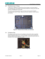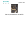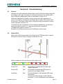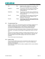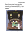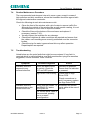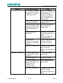
1
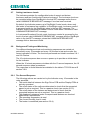
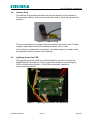
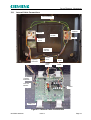
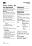
ATLAS GENERAL HANDBOOK Siemens Traffic Controls Sopers Lane Poole Dorset BH17 7ER THIS DOCUMENT IS ELECTRONICALLY HELD AND APPROVED PREPARED: FUNCTION: DATE: ISSUE: HA STORES CODE: Dave Brocklehurst STC Team Leader 26 October 2004 2 MANUAL-0549-1-SPC © Crown Copyright 2004. This Manual was produced by Siemens Traffic Controls for the Highways Agency under Contract 1/147A. All trademarks are acknowledged. 667/HB/31000/000 Issue 2 Page 1 ATLAS GENERAL HANDBOOK SAFETY WARNING HEALTH AND SAFETY AT WORK Safety of Installation Personnel In the interests of health and safety, when installing, using or servicing this equipment the following instructions must be noted and adhered to: (i) Only skilled or instructed personnel with relevant technical knowledge and experience, who are also familiar with the safety procedures required when dealing with modern electrical/electronic equipment, are to be allowed to use and/or work on the equipment. All work shall be performed in accordance with the Electricity at Work Regulations 1989. (ii) Motorway Safety Regulations must be adhered to at all times. (iii) Personnel must take heed of all relevant notes, cautions and warnings in this Handbook and any other Document or Handbook associated with the equipment including, but not restricted to, the following: (a) This is a class 1 LED product. Do not view directly with optical instruments. (b) The equipment must be correctly connected to the specified incoming power supply. (c) Before any installation work is carried out, the mains supply must be isolated/switched off. (d) There are hazardous voltages of 60V AC within the Indicator housing. (e) Any power tools must be regularly inspected and tested. (f) When using a ladder near a carriageway ensure that the area is properly coned and signed. Any ladders must be inspected before use to ensure they are sound and not damaged. Before climbing a ladder, ensure that it is erected properly and is not liable to collapse or move. Personnel must adhere to the current Method Statement that details procedures when using a ladder. (g) Any personnel working on site must wear the appropriate protective clothing. Safety of Road Users It is important that all personnel are aware of the dangers to road users that could arise during installation, repair and maintenance of traffic control equipment. Ensure that the area is coned and signed as necessary to warn motorists and pedestrians of any dangers and to help protect the personnel working on the site. When carrying out Commissioning Tests, measures must be taken to ensure that no untoward signals are seen by road users (e.g. turn indicators inboard and/or post warning notices). 667/HB/31000/000 Issue 2 Page 2 ATLAS GENERAL HANDBOOK PRODUCT SUPPORT Technical Support is provided by STC Engineering for the benefit of the Highways Agency and its installation and maintenance contractors. Technical Support is provided for the items included in the Installation, Commissioning and Maintenance sections of this Handbook. The Telephone Help Line is available between the hours of 9.00 am and 5.00 pm, Monday to Friday (excluding Bank Holidays). Outside office hours use the Fax Help Line. Telephone: (01202) 782444 Fax: (01202) 782545 Gary Winstanley, Project Manager Siemens Traffic Controls Sopers Lane Poole Dorset BH17 7ER 667/HB/31000/000 Issue 2 Page 3 ATLAS GENERAL HANDBOOK MAINTENANCE PROVISION (MP) 1. Product Reference ATLAS Motorway Indicator 2. Specifications The ATLAS Motorway Indicator has been designed to meet the requirements of TR2199 and has been EMC tested to BS EN 50293. 3. Installation and Commissioning Methods of Installation and Commissioning are detailed in the Siemens Traffic Controls document: 667/HB/31000/000 ATLAS General Handbook 4. Spares and Maintenance All maintenance and repairs should be carried out in accordance with the Siemens Traffic Controls document: 667/HB/31000/000 ATLAS General Handbook 5. Modifications There are no approved modifications, with the exception of those listed in the following Siemens Traffic Controls document: 667/HB/31000/000 ATLAS General Handbook 6. Warning Use of components other than those permitted above, or modifications or enhancements that have not been authorised by Siemens Traffic Controls will invalidate any warranty given with this product. MP 06/10/04 Issue 1 667/HB/31000/000 Issue 2 Page 4 ATLAS GENERAL HANDBOOK TABLE OF CONTENTS SAFETY WARNING ........................................................................................................ 2 PRODUCT SUPPORT .................................................................................................... 3 MAINTENANCE PROVISION (MP)................................................................................. 4 Section 1 - Introduction.............................................................................................. 8 1.1 Purpose ................................................................................................................ 8 1.2 Scope ................................................................................................................... 8 1.3 Related Documents .............................................................................................. 8 1.4 Definitions............................................................................................................. 8 1.5 Issue State ........................................................................................................... 9 Section 2 - Standard Atlas Facilities ........................................................................ 10 2.1 General............................................................................................................... 10 2.2 Specification ....................................................................................................... 11 2.3 Power Up and Reset .......................................................................................... 12 2.4 Messages and Replies ....................................................................................... 12 2.5 Watchdog ........................................................................................................... 12 2.6 Setting Aspect and Lanterns .............................................................................. 12 2.7 Setting Luminance Levels .................................................................................. 13 2.8 Background Testing and Monitoring ................................................................... 13 2.8.1 Ten Second Sequence ................................................................................ 13 2.8.2 Ten Minute Sequence ................................................................................. 14 2.8.3 Testing and Monitoring Display Cells .......................................................... 14 2.8.3.1 Passive Monitoring ........................................................................... 14 2.8.3.2 Active Testing and Monitoring .......................................................... 14 2.8.3.3 Aspect Fault Conditions.................................................................... 15 2.8.4 Heater Control ............................................................................................. 15 2.8.5 Lantern Drive and Monitoring ...................................................................... 16 Section 3 - The Equipment ...................................................................................... 17 3.1 General............................................................................................................... 17 3.2 Sign Driver PCB ................................................................................................. 17 3.3 Display PCBs...................................................................................................... 19 3.4 Address Plug ...................................................................................................... 20 3.5 Lightning Protection PCB ................................................................................... 20 3.6 RS485 External Interface ................................................................................... 21 3.7 Power Supply Connection .................................................................................. 21 3.8 Lantern Connection ............................................................................................ 21 3.9 Anti-Condensation .............................................................................................. 21 3.10 Engineer’s Terminal............................................................................................ 22 3.11 Internal Cable Connections ................................................................................ 23 Section 4 - External Interfaces................................................................................. 24 4.1 Introduction......................................................................................................... 24 4.2 RS485 ................................................................................................................ 24 4.3 Engineer’s Terminal Port (RS232)...................................................................... 24 4.4 Power ................................................................................................................. 24 4.5 Lantern Connections .......................................................................................... 25 4.6 Address Port....................................................................................................... 25 667/HB/31000/000 Issue 2 Page 5 ATLAS GENERAL HANDBOOK Section 5 - Installation ............................................................................................. 26 5.1 Scope ................................................................................................................. 26 5.2 Tools Required ................................................................................................... 26 5.3 Disposal of Packaging Materials......................................................................... 26 5.4 Order of Installation ............................................................................................ 26 5.5 Fit Indicator onto ‘X’ Frame ................................................................................ 27 5.6 Fit Address Plug ................................................................................................. 27 5.6.1 Coding the Address Plug............................................................................. 28 5.6.2 Completing the Address Label .................................................................... 28 5.7 Fit Lantern Cable ................................................................................................ 29 5.8 Fit Data Cable..................................................................................................... 29 5.9 Fit Power Cable .................................................................................................. 30 Section 6 - Commissioning ...................................................................................... 31 6.1 General............................................................................................................... 31 6.2 Status LEDs........................................................................................................ 31 6.3 Commissioning Tests ......................................................................................... 32 6.3.1 Address Plug ............................................................................................... 32 6.3.2 Starting Tester............................................................................................. 33 6.3.3 Initialisation.................................................................................................. 33 6.3.4 Testing Communications ............................................................................. 33 6.3.5 Aspect Setting Test ..................................................................................... 34 6.3.6 Self Test and Status Request...................................................................... 34 6.3.7 Lantern Operation ....................................................................................... 34 Section 7 - Maintenance .......................................................................................... 35 7.1 General............................................................................................................... 35 7.2 Disposal Considerations..................................................................................... 35 7.3 Dismantling Instructions ..................................................................................... 35 7.4 Routine Maintenance Procedure ........................................................................ 37 7.5 Troubleshooting.................................................................................................. 37 7.6 On Site Maintenance .......................................................................................... 40 7.7 Off-Site Maintenance.......................................................................................... 40 7.8 Replacing Parts .................................................................................................. 40 7.8.1 Window and Clips........................................................................................ 40 7.8.2 Seal ............................................................................................................. 40 7.8.3 Filters........................................................................................................... 41 7.8.4 Sign Driver PCB .......................................................................................... 42 7.8.5 Display PCB ................................................................................................ 43 7.8.6 Lightning Protection PCB ............................................................................ 44 7.8.7 Rectifier ....................................................................................................... 46 7.8.8 Cables ......................................................................................................... 46 7.8.8.1 Display Cables.................................................................................. 47 7.8.8.2 Lantern Cable ................................................................................... 47 Section 8 - Parts List................................................................................................ 48 INDEX ........................................................................................................................... 49 667/HB/31000/000 Issue 2 Page 6 ATLAS GENERAL HANDBOOK TABLE OF FIGURES Figure 1 – Installed Indicator .................................................................................... 10 Figure 2 – Atlas Exploded View ............................................................................... 17 Figure 3 – Sign Driver Functional Block Diagram..................................................... 18 Figure 4 – Sign Driver PCB connected..................................................................... 19 Figure 5 – Display PCB layout ................................................................................. 19 Figure 6 – Address Plug........................................................................................... 20 Figure 7 – Lightning Protection PCB connected....................................................... 20 Figure 8 – Internal Cable Connections ..................................................................... 23 Figure 9 – External view of Atlas (unconnected) ...................................................... 27 Figure 10 – Address Plug fitted ................................................................................ 27 Figure 11 – Address Label ....................................................................................... 28 Figure 12 – Lantern Cable fitted............................................................................... 29 Figure 13 – Data Cable fitted ................................................................................... 29 Figure 14 – Power Cable fitted................................................................................. 30 Figure 15 – Sunscreen fixings.................................................................................. 35 Figure 16 – Indicator Open....................................................................................... 36 Figure 17 – Sealing Strip fixed to Indicator housing ................................................. 41 Figure 18 – Filter fixed to Indicator housing ............................................................. 41 Figure 19 – Sign Driver PCB connections and fixings .............................................. 42 Figure 20 – Display PCB fixing points ...................................................................... 43 Figure 21 – Bottom ‘A’ Board showing break-off ...................................................... 44 Figure 22 – Lightning Protection PCB ...................................................................... 45 Figure 23 – Rectifier connections ............................................................................. 46 667/HB/31000/000 Issue 2 Page 7 ATLAS GENERAL HANDBOOK Section 1 - Introduction 1.1 Purpose This handbook is intended to enable the user to install, configure and maintain the Atlas Motorway Indicator. 1.2 Scope This handbook is written for the Atlas Motorway Indicator, and is made up of the sections listed below: SAFETY WARNING PRODUCT SUPPORT MAINTENANCE PROVISION (MP) Section 1 - Introduction Section 2 - Standard Atlas Facilities Section 3 - The Equipment Section 4 - External Interfaces Section 5 - Installation Section 6 - Commissioning Section 7 - Maintenance Section 8 - Parts List INDEX Please note that the photographs contained in this document are provided for information and that the product as delivered may differ in detail. 1.3 Related Documents 667/CI/31000/000 Installation Guide for Atlas NMCS2 Motorway Indicator TR2199 Issue B Requirements for NMCS2 Indicator Type 94xx Including Signal Drivers TR2070 Issue F NMCS2 Message Control Point to Point SSL/447/O/25.09.2003 Tester - EMS/EMI/VMS Test Software User Manual (obtainable from Simulation Systems Ltd Tel: (01934) 838803). 1.4 Definitions ABS Atlas 667/HB/31000/000 Acrylonitrile Butadiene Styrene – a type of Plastic STC name for the T94XX Standard Indicator Issue 2 Page 8 ATLAS GENERAL HANDBOOK CTS HA LED NMCS PCB PSU PWM RS232 RS485 SLF STC Tx Rx VCC VF 1.5 Clear to Send Highways Agency Light Emitting Diode National Motorway Communications System Printed Circuit Board Power Supply Unit Pulse Width Modulation - method of luminance control for aspect EIA Data Communications Interface EIA Differential Data Communications Interface Single Lamp Failure Siemens Traffic Controls Transmit Receive Logic power supply Forward Voltage Issue State Pages Current Issue Type Part ID All 1 Meridian 667/HB/31000/000 First issue Meridian 667/HB/31000/000 Re-issue All 2 incorporating comments 667/HB/31000/000 Issue 2 Comments Page 9 ATLAS GENERAL HANDBOOK Section 2 - Standard Atlas Facilities 2.1 General The Atlas Indicator displays aspects and controls the associated lanterns in response to messages sent from the Standard Transponder over an RS485 link. Its purpose is to warn motorists of hazards ahead and to indicate the corresponding action to be taken. Figure 1 – Installed Indicator The Indicator equipment is designed to be located on a slip road leading to the motorway, in the central reservation or on a gantry over the carriageway. The main facilities provided by Atlas are outlined below: ¾ Atlas is a high quality matrix Indicator incorporating a sign driver, designed to integrate into the NMCS2 system. ¾ The Indicator uses LED technology because of its high reliability and low power consumption. ¾ The Indicator is supplied pre-configured with software and operational parameters. Changes to the operational parameters can be made via the Engineers Terminal. ¾ Atlas has three variants, the 9407, 9409 and 9421. Each variant has the ability to display a particular set of aspects in response to commands from the Transponder. The enclosure is manufactured from vacuum formed ABS plastic to provide a lightweight, rigid, strong framework for the Indicator. The window is made from a clear polycarbonate material with an anti-scratch coating. The indicator is designed to fit directly to a standard ‘X’ frame (not supplied). The ‘X’ frame provides either four or eight lanterns (depending on type). The indicator connects to the ‘X’ frame lanterns by means of a dedicated cable. Lanterns are driven and monitored for voltage and current by the Indicator. 667/HB/31000/000 Issue 2 Page 10 ATLAS GENERAL HANDBOOK The Indicator provides for five different aspect luminance levels at locations where the motorway network provides Luminance Broadcast message control and two levels of lantern luminance. Basic Dim/Bright control with just two luminance levels for aspect and lanterns will be available at other locations. The internal PCBs are readily accessible for maintenance and replacement. An innovative internal sunscreen is attached to the display PCBs to prevent sun glare on the Indicator and to provide a distributed anti-condensation function. Temperature and humidity sensors control a heater system attached to the back of the sunscreen that ensures the window remains clear of condensation. The display cells are made up of a number of LEDs, four for each yellow cell and three for each red cell. The yellow and red cells are independently driven so that red cells cannot be inadvertently lit when setting a yellow aspect. A comprehensive monitoring scheme observes the aspect displayed, and amber lanterns are shut down if 13 or more display cell faults are detected. 2.2 Specification Overall size (approx) ¾ 600 high x 700 wide x 220 deep Weight (approx) ¾ Indicator only 12 Kg Total including packaging 17.2 Kg Power requirements ¾ 60VAC 50-60Hz 272W Max Number of Aspects ¾ Normally up to 16. Programmable up to 32. Communication Standard ¾ RS485 (Transponder Link) RS232 (Engineer’s Terminal) Optical specification ¾ TR2136 C Ingress Protection Rating ¾ IPX6 Operating Temperature ¾ -15ºC to +60ºC Operating Humidity ¾ 30% to 100% at <40ºC EMC/RFI Immunity ¾ EN50293 (2001) Vibration/Shock ¾ TR2130 C Random Vibration ¾ EN 60068-2-6 Bump ¾ EN 60068-2-29 Drop and Topple ¾ EN 60068-2-31 Measured power usage1 ¾ 49W 2 ¾ 145W Measured power usage3 ¾ 175W 4 ¾ 81W Measured power usage Measured power usage 1 Display 30, heater off, lanterns dim Display 30, heater on, lanterns dim 3 Display 30, heater on, lanterns bright 4 Display 30, heater off, lanterns bright 2 667/HB/31000/000 Issue 2 Page 11 ATLAS GENERAL HANDBOOK 2.3 Power Up and Reset On power-up or reset, the software is initialised, Atlas performs tests on hardware, initialises internal data, sets the display to OFF and monitors for the correct display status. Atlas then enters normal operating mode and is ready to action messages from the Transponder or Engineer’s Terminal. A reset is only performed if the watchdog timer fails (see section 2.5), if a power failure is detected or if power is cycled. The Atlas circuits are periodically monitored for faults as described in section 2.8. 2.4 Messages and Replies The Indicator receives, acknowledges and acts on messages for its configured address. In addition, it acts on but does not acknowledge Flasher Synchronisation and Luminance Broadcast Messages. Valid messages are as follows: Received Message SET (20H) STATUS REQUEST (22H) TEST (24H) REQUEST TEST RESULT (25H) FLASHER SYNCHRONISATION (27H) LUMINANCE BROADCAST (2AH) DEVICE MODIFICATION REQUEST (30H) Reply Message (to valid message) ACKNOWLEDGEMENT (21H) STATUS REPLY (23H) ACKNOWLEDGEMENT (21H) TEST RESULT (26H) No reply required No reply required DEVICE MODIFICATION REPLY (31H) Full details of messages and replies are contained in TR2199 and TR2070 Section 9, which documents are detailed in Section 1.3 of this handbook. 2.5 Watchdog The hardware watchdog checks periodically that the software is running. If the software fails, the watchdog circuit times out, the Indicator is reset and the watchdog condition is reported in the first STATUS REPLY message. 2.6 Setting Aspect and Lanterns An aspect and lantern combination is set in response to a SET message from the Transponder or the Engineer’s Terminal. The message defines which aspect is to be set, the Dim/Bright setting and which (if any) lanterns are to be controlled. 667/HB/31000/000 Issue 2 Page 12 ATLAS GENERAL HANDBOOK 2.7 Setting Luminance Levels The Indicator provides five configurable levels of aspect and lantern luminance and two fixed levels of lantern luminance. The luminance level can be controlled either from Dim/Bright in the last SET message and/or from a valid LUMINANCE BROADCAST message if one has been received. By default, the Indicator powers up in Dim/Bright Control mode, where only two levels of luminance are available. In Dim/Bright mode, luminance control is governed solely by the Dim/Bright value in the last SET message. The Indicator enters Luminance Broadcast Control mode when it receives a valid LUMINANCE BROADCAST message. In Luminance Broadcast Control mode, luminance control is governed by the level in the last valid LUMINANCE BROADCAST message and the Dim/Bright value in the last SET message, unless the LUMINANCE BROADCAST message fails or becomes invalid. 2.8 Background Testing and Monitoring Two different background test and monitoring sequences are carried out periodically every 10 seconds and every 10 minutes to test and monitor the correct operation of Atlas. The functions performed are listed in sections 2.8.1 and 2.8.2 below. The 10 minute sequence also occurs on power-up to provide an initial status for the Indicator. When the 10 minute sequence coincides with the 10 second sequence, the 10 second sequence takes precedence. The responses to faults detected are detailed in the table in TR 2199 Issue B section 3.9.8. 2.8.1 Ten Second Sequence The following actions are carried out by the Indicator every 10 seconds in the order specified: The serial data link between the Sign Driver PCB and the Display PCBs is actively exercised. The on/off states of the cells are determined to check that the requested aspect is set as required. This is a passive check (see section 2.8.3). The on/off states of the lanterns are determined to check that the requested lanterns are set as required. This is a passive check. The displayed luminance levels for aspects and lanterns are checked against their requirements. The operating temperature is read. The current humidity level is read. The heater is controlled (see section 2.8.4). 667/HB/31000/000 Issue 2 Page 13 ATLAS GENERAL HANDBOOK 2.8.2 Ten Minute Sequence The following actions are carried out by the Indicator every 10 minutes in the order specified: An active check that each display cell can be illuminated and extinguished. An active check that the lanterns can be illuminated and extinguished. A check to determine that the heater can be turned on. A check to determine the correct operation of the lantern and display cell PSUs. A check of the humidity sensor. A check of the temperature sensor. 2.8.3 Testing and Monitoring Display Cells The display cells are each driven by a pulse width modulated (PWM) constant current. The PWM control is used to vary the intensity of the display cells in order to meet the required luminance levels. The constant current control ensures that the LEDs are driven with the correct amount of current regardless of temperature or other operating conditions. All of the red and yellow display cells are made from LEDs connected in series. LED failure open circuit and short circuit are detected by monitoring the constant current driver output voltages. A failure in the constant current driver would also be detected. Display cell fault information is used to update the Indicator internal status and to control the response in STATUS REPLY and TEST RESULT messages. 2.8.3.1 Passive Monitoring The required aspect is passively monitored every 10 seconds by the background test and monitoring facility. Its purpose is to check that those display cells that should be illuminated on the display are still illuminated and those display cells that should not be illuminated are not illuminated. A display cell is deemed to be faulty if it is in an unexpected state when monitored. The number of faulty display cells detected is used to provide a measure of how the integrity of each aspect would be affected were it to be displayed. This measure is specified as Single Lamp Failure, Partial Aspect Failure or Full Aspect Failure and is defined in section 2.8.3.3. 2.8.3.2 Active Testing and Monitoring All the display cells are actively tested and monitored every 10 minutes, irrespective of any aspect that may be currently displayed. In order to perform a test, each of the 139 yellow display cells and 42 red display cells is accessed in turn across the display, starting in the top left hand corner and ending in the bottom right corner. The yellow cells are tested in their entirety before the red cells are tested. Each display cell is inverted, tested and returned to its previous state before moving on to test the next 667/HB/31000/000 Issue 2 Page 14 ATLAS GENERAL HANDBOOK display cell. Each display cell is inverted for the minimum time required to test the inverted state. The duration of the entire test is approximately three seconds and is visually unobtrusive to the casual observer. The number of faulty display cells detected is used to provide a measure of how the integrity of each aspect would be affected were it to be displayed – see section 2.8.3.3. 2.8.3.3 Aspect Fault Conditions Single Lamp Failure When a given aspect contains two or more failed display cells, then the aspect is considered to exhibit a Single Lamp Failure (SLF) condition. The Single Lamp Failure condition is maintained while any aspect has two or more faulty display cells, even if the displayed aspect has fewer than two faulty display cells. Partial Aspect Failure When a given aspect contains between five and 12 faulty display cells, then the aspect is considered to exhibit a partial aspect failure condition. Full Aspect Failure When a given aspect contains 13 or more faulty display cells, then the aspect is considered to exhibit a full aspect failure condition. Amber lanterns are extinguished when the displayed aspect exhibits this fault condition. 2.8.4 Heater Control Once every 10 seconds, the heater on/off control facility is supplied with the latest values of operating temperature and humidity. The facility uses these values to determine the operating state of the heater as on or off. If the operating temperature falls below the configured temperature switching threshold, the heater is turned on to prevent condensation within the Indicator. If the operating temperature exceeds 42ºC, the heater is turned off regardless of the operating humidity level. If the operating temperature is below 42°C but above the configured temperature switching threshold, the heater is turned off unless the operating humidity exceeds the configured humidity switching threshold, in which case the heater remains on. There is hysteresis of 5°C on the temperature switching threshold to prevent repeated close proximity on/off or off/on operations. If the humidity level exceeds the configured humidity switching threshold and the operating temperature is less than 38°C, the heater is turned on to remove the moisture from within the Indicator. When the humidity level falls below the configured humidity switching threshold (and the heater is already on) the heater is turned off, unless the operating temperature is less than the configured temperature switching threshold, in which case the heater remains on. There is hysteresis of 10% on the humidity switching threshold to prevent repeated close proximity on/off or off/on operations. 667/HB/31000/000 Issue 2 Page 15 ATLAS GENERAL HANDBOOK 2.8.5 Lantern Drive and Monitoring The Sign Driver provides the drive and monitoring for the lanterns. Power to the lanterns is provided by a power supply with a controllable output voltage to cater for the required 16V and 22V (Dim, Bright) luminance levels. The power supply has short circuit protection. The Sign Driver monitors each pair of lantern drives for voltage and current. The testing and monitoring of lanterns is not performed when there is an active lantern PSU fault condition, because a lantern PSU fault is identified as a fault on both the amber and red lanterns. The requested lanterns are passively monitored every 10 seconds by the background test and monitoring facility, to check that the lanterns that should be illuminated are still illuminated. All lanterns are actively tested and monitored every 10 minutes by the background test and monitoring facility. The lantern drive voltage and current is monitored in order to detect fault conditions e.g. lamp fail, failure to turn on, failure to turn off, short circuit. 667/HB/31000/000 Issue 2 Page 16 ATLAS GENERAL HANDBOOK Section 3 - The Equipment 3.1 General This document details the following Indicator types: Type HA Stores Code Siemens Part No. 9407 INDICATOR 0075-1-SPC 667/1/31000/007 9409 INDICATOR 0076-1-SPC 667/1/31000/009 9421 INDICATOR 0077-1-SPC 667/1/31000/021 The Indicator type number is printed on a label that can be seen through the front window. Figure 2 – Atlas Exploded View The main components of the Indicator are accessed by removing the window and sunscreen. 3.2 Sign Driver PCB The Sign Driver PCB forms the central intelligence of Atlas and performs five chief functions: Aspect LED drive and monitoring Lantern drive and monitoring Anti-condensation heater drive and monitoring Communication interfaces for the RS485 Transponder Interface and Engineer’s Diagnostic Terminal Power distribution and control for the whole Indicator 667/HB/31000/000 Issue 2 Page 17 ATLAS GENERAL HANDBOOK See the functional block diagram below. Engineers Terminal Connector RS485 Transponder Interface Connector Microcontroller Watchdog Microprocessor Non-volatile Memory RS485 Interface (Transponder) Anti-streaming Read/Write Memory RS232 Interface (Engineers Terminal) UARTS LED CONTROL Display Cards ANALOG_PIXEL_VOLTAGE Digital I/O Analogue to Digital Converter Lantern Drivers Power Connector Address Control Configuration Control Heating System Control ANALOG_PIXEL_VOLTAGE Analogue MUX Power Supply Monitoring Power Distribution Lantern Voltage Monitoring Humidity Sensor Temperature Sensor SIGN DRIVER Address Connector Lantern Connector Figure 3 – Sign Driver Functional Block Diagram 667/HB/31000/000 Issue 2 Page 18 ATLAS GENERAL HANDBOOK The Sign Driver PCB is mounted on the back of the Display PCBs for easy accessibility when the sunscreen/window is removed. Figure 4 – Sign Driver PCB connected 3.3 Display PCBs Atlas is fitted with two different types of display PCB, board ‘A’ and board ‘B’. Viewing the display/sunscreen assembly from the rear, board A is fitted in the top right and bottom left positions whilst board B is fitted in the top left and bottom right positions. Note that board A has a break off tab that is removed when it is fitted in the bottom left position, as shown below. Top of Indicator Board B Board A – arrow points to top of Indicator Board A break-off removed Board B Figure 5 – Display PCB layout 667/HB/31000/000 Issue 2 Page 19 ATLAS GENERAL HANDBOOK 3.4 Address Plug The address plug provided identifies the physical location of the Indicator in the motorway network, and is the same as that used on other HA signal driver products. Figure 6 – Address Plug The plug incorporates a retention chain that attaches securely to the ‘X’ frame or gantry and a label that has the address recorded on it in octal. If the Indicator is replaced for any reason, the address plug is re-used so that the address remains the same in the network. 3.5 Lightning Protection PCB The lightning protection PCB is mounted inside the enclosure close to the RS485 data port (see below). There is sufficient clearance surrounding the PCB to afford spark protection. The PCB is conformally coated for environmental protection. Figure 7 – Lightning Protection PCB connected 667/HB/31000/000 Issue 2 Page 20 ATLAS GENERAL HANDBOOK 3.6 RS485 External Interface A galvanically isolated RS485 interface is provided for motorway communications. It offers an ‘anti-streaming capability’ to ensure faulty units do not ‘lock-up’ the communications channel causing a systems failure. 3.7 Power Supply Connection The power input connects to a 60V (30-0-30V) AC supply derived from a standard Highways Agency approved transformer with a fuse rating of 10A (not supplied). The indicator full-wave rectifies the input voltage via one half of a bridge rectifier. The rectified output is connected to the Sign Driver PCB. On board switched mode power supply units provide the main regulated power requirements for the Sign Driver PCB, for the LEDs on the display cards and for the lanterns. 3.8 Lantern Connection The lanterns are fixed to the ‘X’ frame external to the Indicator. They are driven and monitored by Atlas as described in section 2.8.5. 3.9 Anti-Condensation The Indicator is equipped with a heating system, controlled by the Sign Driver PCB, to ensure there is no build up of condensation on the window. The heater system is capable of power dissipation of up to 100W and is mounted to the rear of the sunscreen. The sunscreen acts like a radiator dispersing the heat over a large area. The proximity of the sunscreen to the window ensures that much of the radiated heat is directed to the window. The Sign Driver PCB monitors the internal temperature and humidity by means of sensors, and automatically switches on the heater as required. Condensation is avoided by controlling the internal temperature ensuring that the dew point is not reached. The heater system also ensures that the Indicator’s internal temperature is maintained at an operational level even when the equipment experiences ambient temperatures of -15°C. No calibration of the temperature or humidity sensors is required. The temperature and humidity set points, by which the heater is controlled, have default values pre-programmed in the Indicator during manufacture. The set points are stored in non-volatile memory. As an extra safety feature the heating system includes an over-temperature switch that isolates the heater if the Indicator temperature rises above a predefined level, regardless of the Sign Driver processor status. 667/HB/31000/000 Issue 2 Page 21 ATLAS GENERAL HANDBOOK 3.10 Engineer’s Terminal An Engineer’s Terminal may be connected to the Indicator via the Test socket on the rear of the housing that is normally covered with a screw-on dust cap. The cap MUST always be replaced after use. 667/HB/31000/000 Issue 2 Page 22 ATLAS GENERAL HANDBOOK 3.11 Internal Cable Connections Earth Assembly Address Comm’s Rectifier Test RS485 A and B Address and Test Lantern Drive Lightning Protection Lantern Drive Power Power Lightning Protection Test and address Heater Display x 4 Figure 8 – Internal Cable Connections 667/HB/31000/000 Issue 2 Page 23 ATLAS GENERAL HANDBOOK Section 4- External Interfaces 4.1 Introduction Atlas is designed to interface to the signals subsystem of the Highways Agency NMCS2 system. 4.2 RS485 A galvanically isolated RS485 interface is provided for motorway communications. Pin A B C D E 4.3 Function Line A Line B NC NC NC Engineer’s Terminal Port (RS232) The Engineer’s Terminal port provides a serial interface for connection to an external Engineer’s Terminal. Pin A B C D E 4.4 Function TX RX RTS CTS GND Power Power is provided via a Highways Agency approved transformer unit. The transformer provides a 30-0-30V AC supply, connected as follows: Pin A B C D 667/HB/31000/000 Function 30 VAC 30 VAC Earth Centre Tap Issue 2 Page 24 ATLAS GENERAL HANDBOOK 4.5 Lantern Connections Each lantern drive line controls one pair of lanterns. All lantern pairs share the same common return. Pin A B C D E F G H 4.6 Function Amber Drive 1 (Top) Amber Drive 2 (Bottom) Red Drive 1 (Right) Red Drive 2 (Left) NC NC 0V Return Earth Address Port The address port has the following connection scheme. Pin A B C D E F G H J K 667/HB/31000/000 Function Indicator Address LSB Indicator Address Indicator Address Indicator Address Indicator Address Indicator Address Link Address Link Address MSB 0V 0V Issue 2 Page 25 ATLAS GENERAL HANDBOOK Section 5 - Installation 5.1 Scope The Atlas Indicator is a component part of the NMCS system. This document details the installation of this component only. The handbook does not specify the testing or procedures required for the installation of the infrastructure. 5.2 Tools Required The following tools are recommended for the installation and maintenance of the Atlas Indicator: 5.3 • M3 Nut spinner to remove/replace display PCBs • Philips screwdriver (No. 1) to remove/replace sunscreen and sign driver PCB • Wire cutter for address plug coding • Highways Agency Tester Software / Terminal Disposal of Packaging Materials All packaging materials must be disposed of in accordance with best practice at the time. Current legislation and environmental considerations must be taken into account at all times. Do not dispose of in household waste sites. 5.4 Order of Installation The recommended order in which installation should take place is as follows: 1. Read the Safety Warning on page 2 of this Handbook 2. Ensure that power is switched off before proceeding. 3. Mount the Indicator on the ‘X’ frame (section 5.5) 4. Prepare the address plug and label (sections 5.6.1 and 5.6.2) 5. Connect the address plug to the Indicator (section 5.6) 6. Connect the lantern cable between the Indicator and the ‘X’ frame (section 5.7) 7. Connect the data cable to the Indicator (section 5.8) 8. Connect the power cable to the Indicator (section 5.9) 9. Ensure that all external cables to the indicator have adequate strain relief. 10. Apply power to Atlas. 11. Ensure the dust cap is in place on the Engineer’s Terminal port. 12. Check the status LEDs through the window (section 6.2). 667/HB/31000/000 Issue 2 Page 26 ATLAS GENERAL HANDBOOK 5.5 Fit Indicator onto ‘X’ Frame A lifting eye is attached to the top fixing of the Indicator (not shown below). Use the lifting eye in accordance with usual procedures, making sure that safe practices are adhered to at all times. The three conical fixing studs fit over and drop into the keyhole shaped mounting holes in the ‘X’ frame. Make sure that the Indicator is secure before proceeding. Figure 9 – External view of Atlas (unconnected) 5.6 Fit Address Plug The address plug must first have its address coded and the label completed before fitting (see sections 5.6.1 and 5.6.2 below). The chain should then be securely attached to the gantry or ‘X’ frame before fixing the plug into place on the back of the Indicator as shown below. Figure 10 – Address Plug fitted 667/HB/31000/000 Issue 2 Page 27 ATLAS GENERAL HANDBOOK 5.6.1 Coding the Address Plug Before connecting the Address Plug to the Indicator, the address must be coded. When supplied, the address plug has all links made and an address of 0. The plug pin numbers are as follows: MSB……………..…………………LSB K J H 0V G F Link E D C B A Indicator Address To code the plug, open it and cut a wire link to a pin to give logic 1. If a link is cut by mistake, it should be reconnected to either pin J or K. Examples of address plug coding are given below: Binary Address Dec Hex Oct Cut plug links for logic 1 H G F E D C B A Link 0 Indicator 1 1 01 001 0 0 0 0 0 0 0 1 Link 3 Indicator 30 222 DE 336 1 1 0 1 1 1 1 0 5.6.2 Completing the Address Label The label is attached to the chain on the address plug. When the plug has been coded, the label must have the address recorded on it in octal by scratching out the relevant numbers. Only one number can be selected in each row and the address on the label must correspond to the address coded in the plug. The label shown has the address of 336 octal (Link 3, Indicator 30). Figure 11 – Address Label 667/HB/31000/000 Issue 2 Page 28 ATLAS GENERAL HANDBOOK 5.7 Fit Lantern Cable Lantern cable connection to Indicator Lantern cable connection to ‘X’ Frame Figure 12 – Lantern Cable fitted Connect the lantern cable between the Indicator and the ‘X’ frame, as shown above, screwing finger tight. After fitting the cable, ensure that the rubber over-moulding is correctly positioned over the connector body. 5.8 Fit Data Cable Data cable Figure 13 – Data Cable fitted Connect the data cable as shown above, screwing finger tight. After fitting the cable, ensure that the rubber over-moulding is correctly positioned over the connector body. 667/HB/31000/000 Issue 2 Page 29 ATLAS GENERAL HANDBOOK 5.9 Fit Power Cable Figure 14 – Power Cable fitted Connect the power cable as shown above, screwing finger tight. After fitting the cable, ensure that the rubber over-moulding is correctly positioned over the connector body. 667/HB/31000/000 Issue 2 Page 30 ATLAS GENERAL HANDBOOK Section 6 - Commissioning 6.1 General Indicators are delivered with software blown into FLASH and ready configured according to their type. Generally no external configuration is needed other than coding the address plug, which is described in section 5.6.1. When the installation has been correctly carried out, after application of power, the Indicator should start operating without further intervention within six seconds. The status LEDs may be viewed through the window to confirm correct operation (section 6.2). Commissioning the equipment involves obtaining satisfactory results to the tests described in section 6.3. If any tests should fail, consult the Troubleshooting table in section 7.5. By default, the Indicator powers up in Dim/Bright Control mode. 6.2 Status LEDs Eight status LEDs are provided on the Sign Driver PCB that may be viewed through the window without having to dismantle the unit. When viewed from the front they are (from right to left): Power VCC Red Illuminated to indicate that the main logic supply is present. Power LED Red Illuminated to indicate that LED power is present for the Display PCBs. Heartbeat Red During initialisation, the heartbeat LED stays illuminated. Pulses periodically during normal Indicator operation i.e. once initialisation has completed. 667/HB/31000/000 Issue 2 Page 31 ATLAS GENERAL HANDBOOK 6.3 Fail Red Indicates a fatal software error condition. This LED is not illuminated for any other reason. RS485 Tx Yellow The pulsing of the LED indicates RS485 data traffic being sent from the indicator to the Transponder link. RS485 Rx Green The pulsing of the LED indicates RS485 data traffic being received by the indicator from the Transponder link. Test Tx Yellow The pulsing of the LED indicates RS232 data traffic being sent from the indicator to the Engineer’s Terminal link. Test Rx Green The pulsing of the LED indicates RS485 data traffic being received by the indicator from the Engineer’s Terminal link. Commissioning Tests In order to carry out site commissioning tests, the Indicator should have its RS485 connection disconnected. A laptop PC with an RS232/RS485 converter and Highways Agency Tester software installed should be connected to the RS485 socket to act as a Transponder Simulator. At the start of each test the indicator should be unpowered with all lanterns connected. The Indicator should display the appropriate outcome for each test. Observe all current safety procedures including those described in, but not limited to, the Safety Warning on page 2 of this Handbook. Particular care should be taken to ensure that any signs under test are not visible to motorists. Carry out the tests in the order given: 6.3.1 Address Plug Check that the address plug may be removed from (and replaced in) the socket, is fitted with a chain secured to the ‘X’ frame and is addressed correctly for the Indicator. Check that the Address Label has been completed with the correct address for the Indicator. 667/HB/31000/000 Issue 2 Page 32 ATLAS GENERAL HANDBOOK 6.3.2 Starting Tester Start the Tester application program. Typically this is via a batch file that invokes the main executable. Full details of the Tester operating instructions are contained in the handbook, detailed in section 1.3 of this document. Tester then displays the “Current Parameters” dialog box. Press F4 and enter the decimal indicator address (see section 5.6.1). Note that this is not the same as the address coded on the address label, which is in octal. Press F5 and enter the correct device type e.g. 9421, 9407, 9409. Respond “NO” to the MS3 prompt. Press Escape. 6.3.3 Initialisation Apply power to the Indicator. Check that no Aspects or Lanterns are lit. Wait six seconds after the application of power and send a STATUS REQUEST, CF=(22H) Message. Check that the following messages have been exchanged between the Indicator and the Tester Transponder Simulator: Address CF DATA1 DATA2 Parity Message Name 01 22 00 00 23 STATUS REQUEST 01 23 80 20 82 STATUS REPLY Check that no Aspects or Lanterns are lit. 6.3.4 Testing Communications From the Tester main screen press F5 for EMI acceptance tests. Press F1 to select “Data Field Errors”. These tests check that the indicator responds to messages only addressed to its device address and checks that it only responds to valid NMCS2 messages. Press F4 to select “Device Mod”. These tests store code and software identification retrieval. Press F5 to select “Protocol and Parameters”. This checks that the software reacts correctly to messages with invalid protocol. Ensure that each of the above tests completes without error. 667/HB/31000/000 Issue 2 Page 33 ATLAS GENERAL HANDBOOK 6.3.5 Aspect Setting Test From the Tester main screen press F5 for EMI acceptance tests. Press F3 to select “All Aspects”. This test instructs the indicator to display each aspect and lantern combination in both “Dim” and “Bright” luminance levels and records the returned status. Ensure that the above test completes without error. 6.3.6 Self Test and Status Request From the Tester main screen press F5 for EMI acceptance tests. Press F6 to select “Self Test and Status Request”. This test instructs the indicator to return the last known test status for each aspect and lantern as well as the global indicator status. Ensure that the above test completes without error. 6.3.7 Lantern Operation From the Tester main screen press F5 for EMI acceptance tests. Press F2 to select “Lantern Operation”. This test sets the lanterns for all combinations and also tests the lantern synchronisation. Ensure that the above test completes without error. 667/HB/31000/000 Issue 2 Page 34 ATLAS GENERAL HANDBOOK Section 7- Maintenance 7.1 General There are three levels of maintenance for Atlas: • Replace on site • Replace off-site • Return to factory Instructions for fitting the parts that are replaceable on- or off-site are given from section 7.8 onward. If any other part fails, the unit should be returned to STC for repair or replacement. Section 8 gives part numbers. 7.2 Disposal Considerations At the end of the product’s life, the indicator, its packaging or any of its component parts, should be disposed of in accordance with best practice at the time. Current legislation and environmental considerations must be taken into account at all times. Do not dispose of any parts in household waste sites. 7.3 Dismantling Instructions Hazardous voltages are present when the unit is powered. Always ensure that the power is disconnected before working inside the Indicator. Before any work is carried out inside Atlas, the Indicator should be removed from the ‘X’ frame. To do this, disconnect the power, data and lantern cables and lift the Indicator up and off the slotted mounting holes in the frame. Fixing position, screw removed Fixing screw in place Figure 15 – Sunscreen fixings 667/HB/31000/000 Issue 2 Page 35 ATLAS GENERAL HANDBOOK When dismantling Atlas, once the window clips are removed, the window is off and the eight fixing screws holding the sunscreen in place have been removed, the front of the unit should be lowered by hinging the sunscreen forward and placing it carefully face down as shown below. There is little slack in the internal cables so take care to support the unit. Alternatively, when the screws have been removed from the sunscreen the whole unit can be gripped firmly by the sides and placed face down on a suitable surface, then the housing can be lifted away. Again, care must be taken not to place strain on internal cables. Figure 16 – Indicator Open See section 5.1 for a list of tools required. 667/HB/31000/000 Issue 2 Page 36 ATLAS GENERAL HANDBOOK 7.4 Routine Maintenance Procedure The recommended maintenance interval is once a year, except in areas of high pollution and dirty conditions, where the timetable should be agreed with the regional maintenance contractor. Check the following at each site maintenance visit: • • • • • 7.5 Clean the front of the window with a jet of water to remove traffic film. Although the outside of the window has an anti-scratch coating, it is not recommended to use a cloth to wipe the window. Check the filters at the bottom of the enclosure and replace if necessary (section 7.8.3). Visually inspect the indicator for any damage. Check and retighten all cable connectors as required and ensure that the rubber over-mouldings are correctly positioned over the connector bodies. Check the sign for water ingress where this may affect operation. Repair/replace as required. Troubleshooting Listed below are the main faults that might be encountered. If any fault is reported which is not listed below, or a fault persists after trying the remedies suggested, consult Siemens Traffic Controls. Symptom Indicator does not respond to any external stimulus. Possible Diagnosis Action Check the status LEDs for activity. Check for VCC and LED power. Indicator un-powered. Ensure that the indicator is powered. Sign Driver PCB is faulty. Check fuse on Sign Driver PCB. Check connections to and if necessary replace the Sign Driver PCB. Indicator does not communicate on the RS485 serial link. Check that the RS485 TX and RS485 RX status LEDs pulse on. Reconnect the RS485 serial cable at the rear of the unit. The RS485 serial cable is disconnected, possibly due to a recent reconfiguration. 667/HB/31000/000 Issue 2 Page 37 ATLAS GENERAL HANDBOOK Symptom Possible Diagnosis Action The Indicator is operating with an address plug set to address 0, i.e. set for configuration mode. Replace the address plug with one set for the correct operating address. The Indicator must be powered off then on to register the address plug. A and B lines connected the wrong way round. Check external wiring infrastructure. The RS485 comm’s cable Open the Indicator unit is disconnected from the and reconnect the lightning protection PCB RS485 cable. and/or the Sign Driver PCB. Lightning protection board faulty Replace the fuse(s) on the lightning protection board. Replace the lightning protection board. The Indicator is configured for the wrong baud rate on the RS485 serial link. Set the RS485 serial link baud rate using the Engineer’s Terminal. Sign Driver PCB is faulty Replace the fuse on the Sign Driver PCB. Replace the Sign Driver PCB. Lanterns not flashing The lantern power cable at the rear of the unit not connected. Connect the lantern power cable. The lamps within the ‘X’ frame have failed. Check and replace lamps as necessary. The internal lantern cable between the Sign Driver PCB and the rear connector is not connected / faulty. Refit / replace internal lantern cable. Sign Driver PCB faulty. Replace the fuse on the Sign Driver PCB. Replace the Sign Driver PCB. 667/HB/31000/000 Issue 2 Page 38 ATLAS GENERAL HANDBOOK Symptom Indicator will not reply to Engineer’s Terminal Possible Diagnosis The RS232 cable is not connected. Action Connect the RS232 cable at the rear of the unit. The RS232 comm’s cable Open the Indicator unit is disconnected from the and reconnect the Sign Driver PCB. RS232 cable. Sign Driver PCB faulty. Replace Sign Driver PCB fuse. Replace the Sign Driver PCB. No display cells on a Display PCB illuminate. The cable between the Sign Driver PCB and the Display PCB is disconnected. Open the Indicator unit and reconnect the cable. Display board faulty. Replace Display board. Sign Driver PCB faulty. Replace Sign Driver PCB fuse. Replace the Sign Driver PCB. Indicator not operating Check that the VCC PWR Check the power cable and LED PWR status is attached to the LEDs are lit. Indicator and the standard transformer. Check that mains power is present to the transformer. 667/HB/31000/000 Software watchdog has triggered. Check the state of the watchdog LED. If lit, power off and on to cause a reset. If the LED lights again, replace the Sign Driver PCB. Incorrect address. Check that the address plug is fitted with the correct address for the Indicator. Issue 2 Page 39 ATLAS GENERAL HANDBOOK 7.6 On Site Maintenance The following items may be replaced on site: 7.7 • Window – see section 7.8.1 • Window clips – see section 7.8.1 • Seal – see section 7.8.2 • Filters – see section 7.8.3 • Address plug – see section 5.6 • Lantern cable – see section 7.8.8.2 Off-Site Maintenance Replacement of the following items should be carried out in the depot or other suitable safe environment: 7.8 • Fuses – see sections 7.8.4 and 7.8.6 • Sign Driver PCB – see section 7.8.4 • Display PCB – see section 7.8.5 • Lightning protection PCB – see section 7.8.6 • Rectifier – see section 7.8.7 • Display Cable – see section 7.8.8.1 Replacing Parts 7.8.1 Window and Clips The window is fixed to the enclosure using a clip on each side, which compresses the window onto the seal. The clips simply pull off and the window may then be lifted away from the seal. The window is screen-printed with black bars that line up with the bars of the sunscreen. It is therefore most important to fit the window the right way up. The identification label should be clearly visible at the bottom left of the Indicator. The clips are then pushed fully into place on each side of the Indicator. 7.8.2 Seal The sealing strip provides a weatherproof seal to the Indicator and has three breaks at the bottom containing filters to act as breather vents. 667/HB/31000/000 Issue 2 Page 40 ATLAS GENERAL HANDBOOK Sealing Strip Figure 17 – Sealing Strip fixed to Indicator housing To replace the seal, first remove the window clips and window. Peel the old sealing strip away from the indicator housing, remove the backing strip from the new seal and stick it into place. Replace the window and clips. 7.8.3 Filters Replaceable filters are fitted to the breather vents on the Indicator housing to prevent insects and other debris getting into the Indicator. To replace them, first remove the window clips and window, then pull the old filter(s) off the Indicator enclosure and clean the area. Peel off the backing strip and stick the new filter(s) to the housing. Filter Figure 18 – Filter fixed to Indicator housing Replace the window and clips. 667/HB/31000/000 Issue 2 Page 41 ATLAS GENERAL HANDBOOK 7.8.4 Sign Driver PCB Display A Not Used Display B Screw points Power +ve Fuse F1 Test and Address Fuse F2 RS485 Data Power -ve Chassis Ground Display A Heater Lanterns Display B Figure 19 – Sign Driver PCB connections and fixings To access the Sign Driver PCB, follow the dismantling instructions in section 7.3. If the sign driver PCB is not working, replace one or both fuses (at F1 and F2) before considering replacing the board. If the sign driver PCB is being removed in order to access a display PCB, it may not be necessary to remove all the cables. Only the four display cables, the test and address cable and the RS485 data cable may need to be disconnected. The other cables can be left connected if more convenient. However, if the sign driver PCB itself is being replaced, then all cables must be disconnected before removing the PCB from its mounting. Remove and retain the four screws and washers that hold the board onto the Display PCBs. 667/HB/31000/000 Issue 2 Page 42 ATLAS GENERAL HANDBOOK To replace the sign driver PCB, make sure that it is the right way up by checking that the arrow printed on the board points to the top of the Indicator. Replace the four screws to hold the board to the Display PCBs. Then reconnect the cables to the PCB as shown above. A fully connected board is shown on page 19. Reassemble the Indicator in reverse order to the dismantling instructions in section 7.3. 7.8.5 Display PCB To access a Display PCB, follow the dismantling instructions in section 7.3. In order to remove and replace a display PCB, the Sign Driver PCB must first be disconnected and put to one side for replacement later. See section 7.8.4 for details. It may be necessary to remove tie-wraps that are holding cables to the board. Fixing points Figure 20 – Display PCB fixing points To remove a Display PCB, undo the four small nuts and retain them and the washers safely. Lift the PCB off its retaining posts and replace with the new board. The bottom ‘A’ board should have the break-off removed before fitting. To help in correct orientation, there is an arrow on the break-off that should point to the top of the Indicator. 667/HB/31000/000 Issue 2 Page 43 ATLAS GENERAL HANDBOOK Snap here Figure 21 – Bottom ‘A’ Board showing break-off The two B boards are identical and are fitted with the top one upright and the other inverted as shown on page 19. Reassemble in reverse order, replacing the Sign Driver PCB and reconnecting the cables and retying where necessary. 7.8.6 Lightning Protection PCB To access the Lightning Protection PCB, follow the dismantling instructions in section 7.3. Lift the protective cover off the PCB and retain for reuse. If the lightning protection PCB fails, replace one or both of the fuse(s) before considering replacing the board. If the board does need replacing, pull apart the bullet connections to disconnect the two comm’s cables (RS485 A and B). Disconnect the lightning protection cable from the Sign Driver PCB and the earth cable from the backplane, removing cable ties where necessary. Undo the four fir tree clips holding the PCB to the strengthening tray and remove the lightning protection PCB. Replace with the new board, by clipping it onto the fir tree clips and replacing the cables (and cable ties where necessary). 667/HB/31000/000 Issue 2 Page 44 ATLAS GENERAL HANDBOOK Bullet connectors Earth cable Fuses Fir Tree Clip x 4 Lightning Protection cable Figure 22 – Lightning Protection PCB Make sure that the clear protective cover is replaced over the board and that the earth cable is re-attached before reassembling the Atlas Indicator. Reassemble the Indicator in reverse order to the dismantling instructions in section 7.3. 667/HB/31000/000 Issue 2 Page 45 ATLAS GENERAL HANDBOOK 7.8.7 Rectifier Rectifier Mounting nut and washer Push-fit cables Figure 23 – Rectifier connections To access the Rectifier, follow the dismantling instructions in section 7.3. To replace the rectifier, first remove the three push-fit cables. The rectifier is held in place with a mounting nut and washer that should be removed. Replace with the new rectifier and fix in place with the nut and washer. Replace the cables as shown below: 30VAC Orange Wire +V to Driver Board Red Wire 30VAC Orange Wire N/C Reassemble the Indicator in reverse order to the dismantling instructions in section 7.3. 7.8.8 Cables Only the cables detailed below can be replaced by maintenance engineers. All other cable replacements should be carried out at the factory. 667/HB/31000/000 Issue 2 Page 46 ATLAS GENERAL HANDBOOK 7.8.8.1 Display Cables The internal short ribbon cables connect each Display PCB to the Sign Driver PCB as shown in Figure 8 on page 23. To access the Display cables, follow the dismantling instructions in section 7.3. To replace a display cable, simply unclip both ends and remove the cable. Replace with the new cable and clip securely into place. Reassemble the Indicator in reverse order to the dismantling instructions in section 7.3. 7.8.8.2 Lantern Cable The external cable that connects the Indicator to the ‘X’ frame can be easily changed. Make sure that the new cable is the correct variant for the Indicator type. The variant is marked on the sleeve. Remove the old cable by peeling back the rubber moulding at each end, unscrew to release it and then screw the new cable securely into place. After fitting the cable, ensure that the rubber over-moulding is correctly positioned over the connector body. See Figure 12 on page 29. 667/HB/31000/000 Issue 2 Page 47 ATLAS GENERAL HANDBOOK Section 8 - Parts List Listed below are the part numbers for the Atlas Indicator spares. See the warning on page 3 regarding the use of parts other than those listed. Part Number 667/1/20982/004 667/1/31020/000 667/1/31030/000 667/1/31032/000 667/2/31010/000 999/4/07849/000 667/7/31018/000 667/HB/31000/000 HA Stores Code INDICATOR – 0086 – 2 – SPC INDICATOR – 0087 – 2 – SPC INDICATOR – 0088 – 2 – SPC INDICATOR – 0089 – 2 – SPC INDICATOR – 0090 – 2 – SPC INDICATOR – 0091 – 2 – SPC INDICATOR – 0092 – 2 – SPC Issue 2 Description Lightning Protection PCB Sign Driver PCB Display PCB ‘A’ Display PCB ‘B’ Window Sealing strip Insect filter Page 48 ATLAS GENERAL HANDBOOK INDEX Luminance level ............................................13 A M Address label ..........................................................28 plug .....................................................20, 27 Aspect setting................................................12 C Maintenance .................................................37 Messages......................................................12 Monitoring .....................................................13 O Cleaning ........................................................37 Commissioning..............................................31 Condensation ................................................21 Configuration.................................................31 D Data cable .....................................................29 Dim/Bright......................................................13 Display cable.................................................47 Display PCB ..................................................19 replacement ..............................................43 Order of Installation.......................................26 Over-temperature switch ..............................21 P Part numbers ................................................48 Partial Aspect Failure....................................15 Power............................................................24 Power cable ..................................................30 Power supply ................................................21 Power up.......................................................12 R F Fault Conditions ............................................15 Filters replacement ..............................................41 Full Aspect Failure ........................................15 H S HA Stores Code ............................................17 Health and Safety............................................2 Heater............................................................21 control .......................................................15 Humidity sensor ............................................21 I Indicator types...............................................17 Installation .....................................................26 Safety.............................................................. 2 Sealing strip replacement..............................................40 Sign Driver PCB............................................17 Single Lamp Failure ......................................15 Size ...............................................................11 SLF ...............................................................15 Spares...........................................................48 Specification..................................................11 Status LEDs ..................................................31 T L Lantern ....................................................16, 21 cable ...................................................29, 47 connections...............................................25 setting .......................................................12 LEDs..............................................................31 Lightning protection PCB ..............................20 replacement ..............................................44 667/HB/31000/000 Rectifier.........................................................46 Replies ..........................................................12 Reset.............................................................12 RS232 ...........................................................24 RS485 .....................................................21, 24 Issue 2 Temperature sensor......................................21 Test socket....................................................22 Tester............................................................33 Tests background...............................................13 commissioning..........................................32 Tools .............................................................26 Troubleshooting ............................................37 Page 49 ATLAS GENERAL HANDBOOK W Watchdog ......................................................12 667/HB/31000/000 Issue 2 Weight...........................................................11 Window replacement..............................................40 Page 50