1
Version: 2008-04-02
technical data:
power supply:
7,5 VDC ; via external power supply
max. power consumption:
750 mA
max. current through ups signal contacts:
ca. 5 mA per signal and multiplexer
max. load per output signal contact:
60 VDC / 0,1 A
pin functions at output ports:
Signal Ground:
Pin 4
AC-Fail (open):
Pin 3-4
AC-Fail (closed):
Pin 2-4
battery low
Pin 5-4
on bypass:
Pin 1-4
summery alarm:
Pin 8-4
shutdown +
Pin 6
shutdown GND
Pin 7
(Pin 4+7 for extension port)
(Pin 4+7 for extension port)
jumper settings:
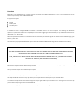
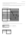
The pin functions for the ups connector are configured with the internal jumper field.
procedure:
- Remove the 4 gray screw covers on the top of the device with a flat screw driver
- unlock the 4 screws and remove the top of the case.
- Check the jumper settings and correct it if necessary.
(unused jumpers should be set on only one pin for storing them)
For the connections and jumper positions see the table below.
For a correct pin configuration at the ups connector it is necessary to understand the function of the
jumper field.