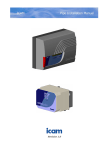
1
T.O.S.C.A. Workstation
with TMS-3 AutoTopographer
USER’S MANUAL
Doc um en t No . 3 10 5 990 0 1
V er s io n 1 .0
Cl os i ng d a te 0 1 /2 0 00
T MS- 3 S of t war e V 2 .2
T .O .S .C . A S of t war e V 2 . 2
O P A S S S of t war e V 2 . 2
As c l ep ion- M ed it e c AG
PR Ü S SI NG ST R AS S E 4 1 · 0 7 74 5 J E N A · G E RM A NY
E XC IM ER HO T LI N E
P ho n e: +4 9 3 6 4 1/ 6 5 22 78 · F ac s im il e: +4 9 3 6 4 1/ 6 5 39 31
e- m ai l: A MJ _ EX CI M ER _ HO T LI N E@c om pus er v e .c om
USER’S MANUAL
Page 2
Document No. 310599001
T.O.S.C.A. TMS-3 WORKSTATION
Dear customer,
you have decided to use the T.O.S.C.A. TMS-3 Workstation.
We congratulate you on your decision!
You now own an advanced system for the topographic acquisition, evaluation and subsequent
correction of the cornea of the human eye.
This system enables you to generate data records for ablation specific to each individual
patient with high precision and transfer the data to the Excimer laser MEL 70 G Scan for
carrying out the treatment.
The video monitor supplying a permanent image of the TMS-3 AutoTopographer camera
picture and the TFT flat screen monitor displaying the user surface in large size will facilitate
your work.
If you have any questions or would like to make any comments, please contact the following
address:
Asclepion-Meditec AG
Prüssingstrasse 41
07745 Jena
Germany
Phone:
+49 36 41/65 32 23
Facsimile:
+49 36 41/65 36 60
Excimer hotline:
Phone:
+49 36 41/65 22 78
Facsimile:
+49 36 41/65 39 31
e-mail:
[email protected]
Version 1.0
Closing date 01/2000
Page 3
USER’S MANUAL
Page 4
Document No. 310599001
T.O.S.C.A. TMS-3 WORKSTATION
Contents
1
General information
7
1.1
Machine identification data....................................................................................................... 7
1.2
Document data ......................................................................................................................... 7
1.3
Purpose of this document......................................................................................................... 7
1.4
Availability of the User’s Manual .............................................................................................. 7
1.5
Complete documentation ......................................................................................................... 8
1.6
Operators.................................................................................................................................. 8
2
Machine description
2.1
Concept .................................................................................................................................... 9
2.2
Construction ........................................................................................................................... 10
2.3
Function.................................................................................................................................. 11
2.4
Technical data ........................................................................................................................ 11
3
Safety instructions
3.1
Customer’s safety obligations ................................................................................................ 13
3.2
Safety alert symbols ............................................................................................................... 13
3.3
Concrete safety instructions ................................................................................................... 14
4
Transport
4.1
Delivery................................................................................................................................... 15
4.2
Transfer to new site................................................................................................................ 15
5
Setting-up
5.1
Requirements on the room..................................................................................................... 17
5.2
Unpacking............................................................................................................................... 17
5.3
Check for short delivery.......................................................................................................... 17
5.4
Installation and layout of the system components ................................................................. 18
5.5
Initial instruction in the use of the system .............................................................................. 18
6
Start-up
6.1
Qualification of the start-up operator ...................................................................................... 19
6.2
Connection of all system components ................................................................................... 19
6.3
Mains power supply................................................................................................................ 20
6.4
Turning the system on/off....................................................................................................... 21
6.5
Installation of the software...................................................................................................... 22
9
13
15
17
19
6.5.1
Installation of the TMS-3 software ........................................................................... 22
6.5.2
Installation of the T.O.S.C.A. software..................................................................... 23
Version 1.0
Closing date 01/2000
Page 5
Inhaltsverzeichnis
USER’S MANUAL
7
Operation
7.1
Qualification of the operator ................................................................................................... 25
7.2
The TMS-3 software ............................................................................................................... 25
7.3
The T.O.S.C.A. software......................................................................................................... 26
7.4
25
7.3.1
Starting the T.O.S.C.A. software.............................................................................. 26
7.3.2
The main menu ........................................................................................................ 26
7.3.3
The top status line .................................................................................................... 27
7.3.4
The menu bar ........................................................................................................... 27
7.3.5
The icon bar ............................................................................................................. 28
7.3.6
The register cards .................................................................................................... 28
7.3.7
The bottom status line .............................................................................................. 31
7.3.8
The color scale ......................................................................................................... 31
7.3.9
The power map ........................................................................................................ 32
7.3.10
Eye type and machine type ...................................................................................... 32
7.3.11
The elevation maps .................................................................................................. 33
Making an examination........................................................................................................... 34
7.4.1
Instructing the patient ............................................................................................... 34
7.4.2
Making a topographic image exposure .................................................................... 34
7.4.3
Generating a data record for ablation ...................................................................... 34
7.4.4
Printing out the data record overview....................................................................... 41
7.5
Transferring the data record to the Excimer laser MEL 70 G Scan ....................................... 42
8
Troubleshooting
8.1
Problems with the hardware ................................................................................................... 43
8.2
Fault messages when using the system ................................................................................ 43
9
Cleaning and maintenance
9.1
Cleaning.................................................................................................................................. 45
9.2
Maintenance ........................................................................................................................... 45
10
Further information
10.1
Accessories and replacement parts ....................................................................................... 47
10.2
Warranty ................................................................................................................................. 47
10.3
Customer service.................................................................................................................... 47
10.4
Conformity statement.............................................................................................................. 48
10.5
Trademarks............................................................................................................................. 49
10.6
Copyright ................................................................................................................................ 49
Page 6
43
45
47
Document No. 310599001
T.O.S.C.A. TMS-3 WORKSTATION
1
General information
1.1
Machine identification data
Machine data
Model designation:
T.O.S.C.A. TMS-3 Workstation
Serial number:
_________________________
Order number:
_________________________
Year of construction:
_________________________
TMS-3 software
License ID:
_________________________
Serial number:
_________________________
T.O.S.C.A. software
License ID:
_________________________
Serial number:
_________________________
WIN 98 operation system
Serial number:
_________________________
Distributor
1.2
1.3
Firm/name:
________________________________________________________
Address:
________________________________________________________
Phone no.:
_________________________
Document data
Document type:
User’s manual
Document number:
310599001
Version:
1.0
Closing date:
01/2000
Purpose of this document
This User’s Manual makes the user of the T.O.S.C.A. TMS-3 Workstation familiar with the
construction, operation, setting-up, handling, safety instructions, cleaning and maintenance of
the system.
1.4
Availability of the User’s Manual
Always keep the User’s Manual and the other documents available to the operator.
The User’s Manual should always be readily available for consultation.
Version 1.0
Closing date 01/2000
Page 7
General information
1.5
USER’S MANUAL
Complete documentation
The scope of delivery of T.O.S.C.A. TMS-3 Workstation the system also comprises the
product descriptions of the system components.
Caution!
The correct use of the TMS-3 AutoTopographer and the handling of the
TMS-3 software are described in the Operator Manual of the supplier,
Fortune Technologies, which is supplied with the machine.
The correct use of the computer and the computer peripherals is described in the
documentation of the respective suppliers. The documentation is supplied with the
machine.
The correct use of the 9" video monitor is described in the video monitor supplier’s
documentation.
The correct use of the 15" TFT flat screen is described in the screen supplier’s
documentation.
1.6
Operators
Danger!
The system must only be used by trained ophthalmologists instructed by
Asclepion-Meditec in the construction, operation, handling, safety instructions,
cleaning and maintenance of the machine.
The instruction shall be recorded and signed in a transfer certificate.
Additional requirements, qualifications or know-how are identified in the chapters of this
User’s Manual.
Danger!
The TOSCA program should not be solely relied on for determining pre-operative
or post-operative procedures. As there is potential for serious injury including
patient discomfort, pain, disorientation, loss of degrees of sight and blindness
from improper use, at all times the user of the software should be a trained
ophthalmologist familiar with the use and operation of the software and theories
behind TOSCA.
The user of the program should rely on his or her own skill, knowledge, expertise
and judgment when making decisions as to operative procedures and should not
rely solely on the suggested parameters provided by the software, which is a
calculating tool only dependent on data acquired by topography machines.
Page 8
Document No. 310599001
T.O.S.C.A. TMS-3 WORKSTATION
2
Machine description
2.1
Concept
The T.O.S.C.A. TMS-3 Workstation is an advanced system for the acquisition and diagnosis of
the superficial conditions of the cornea. The system supplies data for the planning, design and
later performance of refractive intervention with the Excimer laser MEL 70 G Scan..
With a CCD camera, the TMS-3 AutoTopographer scans the patient’s eye and generates the
elevation contour of the cornea. The required data record is generated by the TMS-3 software
supplied with the TMS-3 AutoTopographer.
The TMS-3 data record is sent to the T.O.S.C.A. software. The user can verify the data string
with the T.O.S.C.A. software, reference it to other diagnostic data, edit data and finally
generate a data record for an Excimer laser MEL 70 G Scan..
Now the OPASS software processes the data on the Excimer laser MEL 70 G Scan..
T.O.S.C.A. TMS-3 Workstation
TMS-3
AutoTopographer
Excimer laser MEL 70 G-Scan
T.O.S.C.A.
Workstation
TMS-3 software
OPASS software
T.O.S.C.A. software
Version 1.0
Closing date 01/2000
Page 9
Machine description
2.2
USER’S MANUAL
Construction
1
2
3
4
5
Legend:
1
TMS-3 AutoTopographer with power supply cable and parallel cable to the computer
2
Video monitor 9" with power supply cable and connecting cable to the TMS-3 AutoTopographer
3
TFT flat screen 15" with power supply unit and connecting cable to the computer
4
Computer table
5
Computer with power supply cable, mouse and keyboard
Page 10
Document No. 310599001
T.O.S.C.A. TMS-3 WORKSTATION
2.3
Function
The CCD camera of the TMS-3 AutoTopographer produces the elevation contour of the
examined patient’s eye.
The image captured by the camera is displayed on the video monitor in real-time mode.
The connected computer processes all data and allows user intervention with the software.
The TMS-3 software interprets the results of the camera and generates the data records.
These data records are sent to the T.O.S.C.A. software for processing. The user can verify the
data contents, reference data to other diagnostic data and edit data.
The revised data records can then be transferred to an Excimer laser MEL 70 G Scan for
further processing by the OPASS software.
2.4
Technical data
T.O.S.C.A. TMS-3 Workstation (overall system)
Dimensions W × D × H:
1.5 m × 1.0 m × 1.4 m
Weight:
40 kg
Power supply:
220–230 V, single-phase, 6 A, 50–60 Hz
Power consumption:
150 W
Class of electric protection:
1, type B, continuous service
License/test:
CE label
Ambient conditions:
15–35°C, 20–50 % RH
TMS-3 AutoTopographer
Caution!
For technical data and further specification details, please refer to the operator
manual of the supplier, Fortune Technologies.
Computer
Caution!
For technical data and further specification details of the computer, please refer to
the computer supplier’s documentation in the supply.
Video monitor 9"
Caution!
Version 1.0
For technical data and further specification details of the video monitor, please
refer to the video monitor supplier’s documentation in the supply.
Closing date 01/2000
P a g e 11
Machine description
USER’S MANUAL
TFT flat screen 15"
Caution!
For technical data and further specification details of the TFT flat screen, please
refer to the screen supplier’s documentation in the supply.
Computer table
Dimensions W × D × H:
1.5 m × 1.0 m × 0.8 m
Weight:
26 kg
Material:
Metal frame with plastic-coated table top panels
Carrying power:
12 kg each panel
Page 12
Document No. 310599001
T.O.S.C.A. TMS-3 WORKSTATION
3
Safety instructions
3.1
Customer’s safety obligations
The T.O.S.C.A. TMS-3 Workstation was designed and produced in accordance with the
applicable harmonized norms and further technical specifications. It is a state-of-the-art
product and warrants the highest measure of safety.
This level of safety can be maintained in practical use of the system only if all required
measures are taken. It is the obligation of the customer of the system to plan and supervise
the performance of these measures.
The customer is responsible, in particular to ensure the following:
• to use the system only for the intended purpose;
• to operate the system only in perfect technical state with no function impaired;
• to maintain the User’s Manual and all OEM documentation material in good condition and
complete and store them on or near the machine;
• to allow only sufficiently qualified and authorized personnel to operate, maintain and repair
the machine;
• to ensure regular instruction of such personnel in all matters pertaining to the machine and
any of its components and make certain that all operators know the User’s Manual and, in
particular, the safety instructions;
• to make certain that none of the hazard warning labels on the system is removed or made
illegible.
3.2
Safety alert symbols
The following safety alert symbols indicate important safety messages in this User’s Manual.
When you see this symbol, carefully read the message that follows be alert to the possibility of
personal injury or death.
Danger!
This symbol indicates a hazardous situation which, if not avoided, will result in
death or serious injury.
Caution!
This symbol indicates a hazardous situation which, if not avoided, will result in
damage to the machine, material or the environment.
Note!
This symbol indicates information for the better understanding of the machine.
Version 1.0
Closing date 01/2000
P a g e 13
Safety instructions
3.3
USER’S MANUAL
Concrete safety instructions
Danger!
The TOSCA program should not be solely relied on for determining pre-operative
or post-operative procedures. As there is potential for serious injury including
patient discomfort, pain, disorientation, loss of degrees of sight and blindness
from improper use, at all times the user of the software should be a trained
ophthalmologist familiar with the use and operation of the software and theories
behind TOSCA.
The user of the program should rely on his or her own skill, knowledge, expertise
and judgment when making decisions as to operative procedures and should not
rely solely on the suggested parameters provided by the software, which is a
calculating tool only dependent on data acquired by topography machines.
Danger!
All work on the electrical equipment of the system must only be carried out by a
trained electrician.
It is not allowed to connect several components of the system by portable multiple
socket outlets sharing a common grounding cable.
Always use the isolating transformer with multi-outlet distribution unit supplied
with the machine.
Never clean or bring the electrical components of the system in contact with water
or a similar liquid.
Lay the electrical cables and lines supplying the system in such a way that they do
not constitute a tripping hazard.
Regularly inspect the safe standing of the system.
Do not make any changes to any system of the component without the supplier’s
authority.
Use only original replacement parts / original wearing parts / original accessory
items. These parts and items are specially designed for the system. The use of
parts other than original does not ensure design and manufacture in accordance
with the service and safety requirements of the machine.
Parts and optional accessories which are not supplied with your order are not
released by us for use with your particular system.
Inspect the electrical equipment regularly for proper seating and connection,
damage to cables, lines and housing.
Disconnect the power supply immediately in case of fire.
Extinguish fire only with CO2 or powder extinguisher.
Page 14
Document No. 310599001
T.O.S.C.A. TMS-3 WORKSTATION
4
Transport
4.1
Delivery
The consignment with the T.O.S.C.A. TMS-3 Workstation was delivered to our carrier in
undamaged condition and complete with all required papers. The carrier delivering the system
to your place is responsible for speedy and safe transport and delivery of the consignment to
you without damage.
If on inspection of the consignment on receipt you find short delivery or damage in transit,
this is the responsibility of the carrier delivering the consignment. If you find damage to the
consignment in transit, please observe the following points:
• Insist that carrier make a note of the nature of the defect on the consignment note.
• The carrier should immediately inspect the damage or determine the value of the items in
short delivery.
• Inform the competent insurance company of the damage or short delivery without delay.
Only the insurance company will pay for the supply of the lost or damaged items in the
consignment.
• If you fail to note any damage during a visual inspection of the consignment packages but
on unpacking you find that a component of the system has been damaged and provided
such damage has been caused in transit, inform the carrier of the facts without delay and
insist that an inspection of the system components is made.
• Do not dispose of the original packaging unless all matters have been settled with the
carrier and the insurance company.
4.2
Transfer to new site
If later you want to transfer the system to a new site, observe the following points:
• Make sure that no component can drop to the ground.
• The floor over which the system is transported should be level and have sufficient carrying
power for vibration-free transport of the system.
Caution!
The system is a measuring instrument of high precision which must not be
exposed to strong vibration.
Non-level ground can damage the system.
Version 1.0
Closing date 01/2000
P a g e 15
Transport
Page 16
USER’S MANUAL
Document No. 310599001
T.O.S.C.A. TMS-3 WORKSTATION
5
Setting-up
5.1
Requirements on the room
The room in which the T.O.S.C.A. TMS-3 Workstation is installed and operated should permit
electrical supply in accordance to national requirements, have a firm floor with a minimum
carrying capacity of 500 kg/m².
Danger!
5.2
Use the system only in a room with electrical installation satisfying the national
requirements.
Unpacking
All supplied components will be unpacked by a service technician of Asclepion-Meditec.
5.3
Check for short delivery
Together with the Asclepion-Meditec service technician, inspect the consignment if all
components needed to operate the system have actually been delivered.
The system consists of the following components:
• TMS-3 AutoTopographer with power supply cable, parallel cable to the computer and the
operator manual of the supplier, Fortune Technologies;
• the computer with power supply cable, mouse, keyboard, and instruction material
• the 15" TFT flat monitor screen with power supply unit, connecting cable to the computer,
and instruction material
• the 9" video monitor with power supply cable, connecting cable to the
TMS-3 AutoTopographer, and instruction material
• the isolating transformer with multi-outlet distribution unit (5 outlets)
• the computer table
• one ZIP installation disk with the T.O.S.C.A. software
• one 3½" installation disk with the TMS-3 software
• the user’s manual of the supplier, Asclepion-Meditec
Version 1.0
Closing date 01/2000
P a g e 17
Setting-up
5.4
USER’S MANUAL
Installation and layout of the system components
All system components are installed by a service technician of Asclepion-Meditec.
The layout of the system components is largely determined by the shape of the computer table.
You can arrange the monitor screens to your most comfortable position.
Danger!
Cable ends and components live with electric power can cause electric injury.
Lay the electrical cables and lines supplying the system in such a way that they do
not constitute a tripping hazard.
Caution!
Wrongly placed or improperly mounted parts can drop to the ground and cause
personal injury.
Improperly installed cables and lines (e. g., if laid with close bending radius) can
smoulder or catch fire.
Electronic assemblies can be damaged by electrostatic processes.
5.5
Initial instruction in the use of the system
The service technician from Asclepion-Meditec installing the system carries out the function
test and instructs the operators of the system in its use as required under MPG and
EC directive.
The fact that the instruction was carried out shall be recorded in the delivery document of the
system.
Page 18
Document No. 310599001
T.O.S.C.A. TMS-3 WORKSTATION
6
Start-up
6.1
Qualification of the start-up operator
The first start-up of a new system is the job of an authorized representative of AsclepionMeditec who explains all involved steps to the customer’s operators.
6.2
Connection of all system components
All connections are made on the rear of each component.
Caution!
Make sure of the proper seating of all plugs.
2
3
a
b
4
5
c
6
d
e
1
PRINTER
System components:
Connections:
1
Computer
a
Mouse cable
2
Mouse
b
Keyboard cable
3
Keyboard
c
Monitor screen connection
4
15" TFT flat screen
d
TMS-3 - monitor screen
5
9" video monitor screen
e
TMS-3 - computer
6
TMS-3 AutoTopographer
Version 1.0
Closing date 01/2000
P a g e 19
Start-up
6.3
USER’S MANUAL
Mains power supply
The T.O.S.C.A. TMS-3 Workstation is supplied with single-phase power
220–230 V, 50 Hz, 6 A fused.
To connect the system to the power source, proceed as follows:
1. Make sure that all system components and the isolating transformer are turned off.
2. Make sure that the voltage specified on the nameplate on the rear of each system
component agrees with the voltage of your socket outlet.
Check to make sure that that the power supply cable can be used on your power source.
3. Connect all system components to the multi-outlet distribution unit using the delivered
power supply cables.
4. Plug the isolating transformer in a properly grounded socket outlet.
Danger!
Use the system only in a room with electrical installation satisfying the national
requirements.
It is not allowed to use portable multiple socket outlets sharing a common
grounding cable to connect several components of the system.
3
a
4
b
5
c
d
2
PRINTER
e
1
System components:
1
Connections:
Isolating transformer with multi-outlet
a
Computer power supply cable
distribution unit (5 outlets)
b
Power supply cable with power supply unit
2
Computer
3
15" TFT flat screen
c
9" video monitor screen power supply cable
4
9" video monitor screen
d
TMS-3 AutoTopographer power supply cable
5
TMS-3 AutoTopographer
e
Isolating transformer mains power connection
Page 20
of the 15" TFT flat screen
Document No. 310599001
T.O.S.C.A. TMS-3 WORKSTATION
6.4
Turning the system on/off
Turn the T.O.S.C.A. TMS-3 Workstation on/off at the isolating transformer.
It is also possible to turn the system components on or off at the mains switch of each
component.
For details of the location of the mains power switch on each component, please refer to the
illustration below.
Note!
1
Please turn the system on or off at the isolating transformer.
2
3
4
5
d
b
c
e
a
System components:
On/off switch
1
Isolating transformer
a
Isolating transformer on/off switch
2
TMS-3 AutoTopographer
b
TMS-3 AutoTopographer on/off switch
3
9" video monitor screen
c
Video monitor screen on/off push-button
4
15" TFT flat screen
d
TFT flat screen on/off push-button
5
Computer
e
Computer on/off push-button
Version 1.0
Closing date 01/2000
P a g e 21
Start-up
6.5
USER’S MANUAL
Installation of the software
The complete software required by the system is already installed on the computer and ready
for use when it is delivered.
If you want to re-install the software, follow the instructions on this and the following pages.
Caution!
Store the installation disks at a safe place. Do not expose the installation disks to
strong magnetic field, heat or cold, direct sunlight, moisture or dust.
6.5.1 Installation of the TMS-3 software
For a description of the installation of the TMS-3 software, refer to the delivered operator
manual of the supplier, Fortune Technologies.
Page 22
Document No. 310599001
T.O.S.C.A. TMS-3 WORKSTATION
6.5.2 Installation of the T.O.S.C.A. software
1.
Start Windows, unless already running.
2.
Load the T.O.S.C.A. installation disk in the ZIP
drive of the computer.
3.
Wait for the installation window display.
The installation disk is self-starting.
If the installation will start automatically, start it
manually by selecting the SETUP.EXE file.
Please read the disclaimer notice carefully.
If you do not agree to the terms and conditions,
click <Not Accepted>.
If you agree to the terms and conditions, you can
proceed with the installation.
Record your license ID.
To know your serial number, please dial the
following number: +49 36 41/ 65 22 78.
You can also send us an e-mail or a fax
transmittal.
4.
Enter your serial number in the red input field. If
the number is correct, the color of the input field
changes to white.
If you want to proceed with the installation click
the <Accepted> button once
If you do not want to go ahead with the
installation, click the <Not Accepted> button once.
This completes the installation process.
Please remove the installation disk from the ZIP
drive of your computer.
Version 1.0
Closing date 01/2000
P a g e 23
Start-up
Page 24
USER’S MANUAL
Document No. 310599001
T.O.S.C.A. TMS-3 WORKSTATION
7
Operation
7.1
Qualification of the operator
The T.O.S.C.A. TMS-3 Workstation must only be used by qualified and instructed
ophthalmologists.
Danger!
The TOSCA program should not be solely relied on for determining pre-operative
or post-operative procedures. As there is potential for serious injury including
patient discomfort, pain, disorientation, loss of degrees of sight and blindness
from improper use, at all times the user of the software should be a trained
ophthalmologist familiar with the use and operation of the software and theories
behind TOSCA.
The user of the program should rely on his or her own skill, knowledge, expertise
and judgment when making decisions as to operative procedures and should not
rely solely on the suggested parameters provided by the software, which is a
calculating tool only dependent on data acquired by topography machines.
The operator of the system must have knowledge of the WIN 98 operating system.
7.2
The TMS-3 software
The use of the TMS-3 software is described in the delivered operator manual of the supplier,
Fortune Technologies.
Version 1.0
Closing date 01/2000
P a g e 25
Operation
7.3
USER’S MANUAL
The T.O.S.C.A. software
7.3.1 Starting the T.O.S.C.A. software
To start the software, double-click the TOSCA
icon.
The main menu of the software is displayed.
7.3.2 The main menu
1
2
3
4
5
6
7
8
9
Legend:
Page 26
1
Top status line
2
Menu bar
3
Icon bar
4
Register cards
5
Bottom status line
6
Color scale
7
Power map
8
Eye type and machine type
9
Elevation maps
Document No. 310599001
T.O.S.C.A. TMS-3 WORKSTATION
7.3.3 The top status line
1
2
34 5
Legend:
1
File name of the current file
2
Software name
3
Minimize window
4
Maximize window
5
Close the software
7.3.4 The menu bar
1
2
3
Legend:
1.1
Opens the window to select a patient data record
1.2.1
1.2.2
1.2.3
1.2.1
Prints the current file
1.2.2
Opens the file print preview window
1.3
1.2.3
Opens the “Printer Set-up” window of the currently
selected printer
1.3
Displays the two files opened last
1.4
Quits the current program
2.1
Opens the “Map Options” selection window
2.2.1
2.2.2
2.2.1
Hides/shows the icon bar
2.3.1
2.3.2
2.3.3
2.3.4
2.2.2
Hides/shows the bottom status bar
2.3.1
Displays the content of the “Data” register card
2.3.2
Displays the content of the “Patient” register card
2.3.3
Displays the content of the “Refract” register card
2.3.4
Displays the content of the “TSA” register card
3.1
Displays help topics for using the T.O.S.C.A.
software
3.2
Displays information on the T.O.S.C.A. installation
data
1.1
1.4
2.1
3.1
3.2
Version 1.0
Closing date 01/2000
P a g e 27
Operation
USER’S MANUAL
7.3.5 The icon bar
1
2
3
4
5
6
7
8
9
Legend:
1
Opens the window to select a patient data record
2
Quits the current program
3
Opens the print preview window of the file
4
Prints the current file
5
Displays the current file prior to simulation of
treatment
6
Displays the current file after simulation of
treatment
7
Opens the tutorial on T.O.S.C.A.
8
Displays help topics for using the T.O.S.C.A.
software
9
Displays information on the T.O.S.C.A. installation
data
7.3.6 The register cards
1
2
3
4
Legend:
1
Displays the value under the mouse pointer
2
Displays the available patient data
3
Enables entry of the refraction data
4
Enables entry of the shift of the reference area in
the Z axis
1.1
Legend:
1.1
Page 28
Displays the value under the mouse pointer.
Document No. 310599001
T.O.S.C.A. TMS-3 WORKSTATION
2.1
2.2
2.3
2.4
Legend:
3.1
3.2
2.1
Displays the patient’s family name
2.2
Displays the patient’s first name
2.3
Displays the patient’s date of birth
2.4
Displays the date of the topographic image
exposure
3.3
3.4
Legend:
3.1
Enables the entry of the correction values for the
sphere data
3.2
Enables the entry of the correction values for the
cylinder data
3.3
Enables the entry of the correction values for the
axis data
3.4
Starts the new calculation with the refraction data
The newly calculated elevation contour is
displayed in the “Target” window.
Note!
The values for sphere, cylinder and axis are entered with the arrow keys beside the
input fields.
The values are entered in steps of 0.25 dpt and 5 °, respectively
either as incrementing or decrementing value steps.
The maximum values for sphere and cylinder are ± 12,5 dpt.
The maximum value for axis is 0–180 °.
Version 1.0
Closing date 01/2000
P a g e 29
Operation
USER’S MANUAL
3.5
Legend:
3.5
Generates a data record for ablation on the
Excimer laser MEL 70 G Scan..
The generated data record is written directly on a
ZIP disk.
Caution!
4.1
Load a ZIP disk with sufficient free memory space in the ZIP drive of the computer
before starting the <Shaping> function.
4.2
4.3
4.4
Legend:
4.1
Enables entry of the correction values for the shift
of the reference area in the Z axis
4.2
Status message
4.3
Status message
4.4
Starts the new calculation with the refraction data.
The newly calculated elevation contour is
displayed in the “Target” window.
Note!
The values for Z shifting are entered with the arrow keys beside the input fields.
The values are entered in steps of 1 µm either as incrementing or decrementing
value steps.
The maximum value for Z shifting is ± 100 µm.
The refraction data are still enabled in TSA mode even if the value calculated by the
software is disabled in TASA mode.
After completing the <Apply> function, a new shift value can be defined by mouseclicking the “Target” window.
Page 30
Document No. 310599001
T.O.S.C.A. TMS-3 WORKSTATION
4.5
Legend:
4.5
Generates a data record for ablation on the
Excimer laser MEL 70 G Scan..
The generated data record is written directly on a
ZIP disk.
Caution!
Load a ZIP disk with sufficient free memory space in the ZIP drive of the computer
before starting the <Shaping> function.
7.3.7 The bottom status line
2
1
3
4
Legend:
1
Displays messages according to the current
conditions.
2
Not assigned.
3
Indicates if the number field of the keyboard is
turned on or off.
4
Not assigned.
7.3.8 The color scale
The color scale displays all colors used, together
with their dpt values.
The color scale can change its appearance
depending on the source of the invoked patient
data record.
Version 1.0
Closing date 01/2000
P a g e 31
Operation
USER’S MANUAL
7.3.9 The power map
1
2
4
3
Legend:
1
Displays the curvature of the cornea as a color
contour, together with the assigned dpt values.
2
Temporal
3
Angle matrix in 10 ° steps
4
Nasal
7.3.10 Eye type and machine type
Legend:
1
Displays the eye type
2
Displays the machine type
1
2
Page 32
Document No. 310599001
T.O.S.C.A. TMS-3 WORKSTATION
7.3.11 The elevation maps
Legend:
1a
The “Elevation” window displays the elevation
contour of the cornea.
Elevation is indicated in units of µm.
1a
1b
Before the <Apply> function is performed to obtain
an elevation contour of the cornea, the “Target”
window is blank.
2a
After performing the <Apply> function the current
display of the cornea in the “Elevation” window
remains displayed.
2b
After performing the <Apply> function the
elevation contour of the “Elevation” window
corrected for the entered refraction data is
displayed in the “Target” window.
1b
2a
The elevation values are displayed in units of µm.
2b
3a
3a
After using the <Shaping> function, the result of
treating the cornea is displayed in a simulation
capture in the “Elevation Sim” window.
3b
After using the <Shaping> function, the “Target”
window changes to the “Ablation” window.
The “Ablation” window displays the elevation values
of the ablation to be made.
The elevation values are displayed in units of µm.
3b
Version 1.0
Closing date 01/2000
P a g e 33
Operation
7.4
USER’S MANUAL
Making an examination
7.4.1 Instructing the patient
Explain the patient what is going to happen during the examination
Explain the further procedural steps to the patient.
Caution!
The set-up of the patient place and the handling of the TMS-3 AutoTopographer
are described in the operator manual of the supplier, Fortune Technologies.
7.4.2 Making a topographic image exposure
The topographic image exposure is made and the appropriate patient data record generated
with the TMS-3 AutoTopographer using the TMS-3 software.
Caution!
The topographic image exposure is described in the operator manual of the
supplier, Fortune Technologies.
7.4.3 Generating a data record for ablation
The further processing of the topographic data runs under the T.O.S.C.A. software
1.
Start the T.O.S.C.A. software.
To start the software, double-click the
TOSCA icon.
The main menu of the software is displayed.
2. Invoke the patient database
Click <Open> in the icon bar of the main menu.
The patient database is displayed.
Page 34
Document No. 310599001
T.O.S.C.A. TMS-3 WORKSTATION
3. Select a patient data record
Click the required data record.
The selected data record is highlighted blue.
Confirm your selection by clicking <Open>.
Click <Cancel> to exit the selection window
without enabling a data record.
4.
Verify the patient data
To verify the patient data, click the <Patient>
register card.
Version 1.0
Closing date 01/2000
P a g e 35
Operation
5.
USER’S MANUAL
Enter the refraction values
a
c
b
Page 36
a)
Open the <Refract> register card.
b)
Enter the patient’s current refraction values in the
input fields.
c)
Click the <Apply> button to obtain the display of
the new calculation in the “Target” window.
Document No. 310599001
T.O.S.C.A. TMS-3 WORKSTATION
6.
Determine the elevation values in the “Target” window
b
a
a)
Open the <Data> register card.
b)
Place the mouse pointer over the “Target”
window.
The current value is displayed in the display
window below the mouse pointer.
Determine the highest elevation value along the
second ring (counting from the center point).
Version 1.0
Closing date 01/2000
P a g e 37
Operation
7.
USER’S MANUAL
Set the depth of treatment
b
Danger!
Page 38
a
c
a)
Open the <TSA> register card.
b)
Enter the value of the shift of the reference area in
the Z axis.
c)
Click the <Apply> button to obtain the display of
the new calculation in the “Target” window.
If you change the depth by a shift of the reference area in the Z axis, you also
change the size of the treatment area.
Document No. 310599001
T.O.S.C.A. TMS-3 WORKSTATION
8.
Generate a data record for ablation
b
a
a)
Click the <Shaping> button.
A data record for ablation is generated.
The generated data record is written directly on
the ZIP disk in the ZIP drive of your computer.
b)
After using the <Shaping> function, the result of
treating the cornea is displayed in a simulation
capture in the “Elevation Sim” window.
The “Ablation” window displays the elevation values
of the ablation to be made.
Caution!
Version 1.0
Load a ZIP disk with sufficient free memory space in the ZIP drive of the computer
before starting the <Shaping> function.
Closing date 01/2000
P a g e 39
Operation
9.
USER’S MANUAL
Verify the result
c
b
a
a)
Open the <Data> register card.
b)
Place the mouse pointer above the “Target”
window. The current value is displayed in the
display window below the mouse pointer.
Adjust the elevation value to the patient data.
Note!
The lowest point in units of µm should approximately be equal to the refraction
(sph + cyl) in units of dpt, multiplied by 13 µm/dpt (plausibility check). If you are in
doubt, select a new Z shift value.
c)
Click the <Pre Sim> button to restore the status
before the data record for ablation was generated.
10. Correct the settings, if necessary
If you think that the depth should be corrected, open the <TSA> register card once more.
Make the required change by entering a different value.
To obtain a new preview, repeat the <Apply> and <Shaping> functions.
Danger!
Page 40
If you change the depth by a shift of the reference area in the Z axis, you also
change the size of the treatment area.
Document No. 310599001
T.O.S.C.A. TMS-3 WORKSTATION
7.4.4 Printing out the data record overview
1.
Print Set-up
Click the <Print Setup> button in the <File> menu.
Select the printer that is connected to the system.
Complete the required settings.
To confirm the entries, click <OK>.
Note!
2.
The data screen for the output of the data record overview uses a A4 landscape
format as a default.
Print Preview
Click the <Preview> button on the icon bar.
The “Print Preview” window is displayed.
b
c
d
a) It contains an overview of all relevant data.
b) A print-out can be obtained from the
“Print Preview” window.
c) The preview display can be zoomed in or out.
d) Closes the “Print Preview” window.
a
3.
Print
Click the <Print> button on the icon bar.
The data record overview is printed out.
Note!
Version 1.0
Print out the data on a color printer.
Closing date 01/2000
P a g e 41
Operation
7.5
USER’S MANUAL
Transferring the data record to the Excimer laser MEL 70 G Scan
1. Remove the ZIP disk from the computer’s ZIP drive.
2. Load the ZIP disk in the ZIP drive of the Excimer laser MEL 70 G Scan..
3. Start the OPASS software unless already started.
4. Select the required data record in drive “E:” and open the data record.
Note!
All patient data records use the extender “DAT”.
5. Again verify the correctness of the selected patient data record.
Danger!
If by chance you should select wrong patient data, serious injury can be caused by
the treatment.
6. Now you can start the treatment in accordance with the operating instructions and the
application manual of the Excimer laser MEL 70 G Scan..
Danger!
Page 42
This User’s Manual of the T.O.S.C.A. TMS-3 Workstation is not an instruction to
carry out the treatment on the Excimer laser MEL 70 G Scan.. Always refer to the
operating instructions and the application manual of the Excimer laser MEL 70
G Scan.
Document No. 310599001
T.O.S.C.A. TMS-3 WORKSTATION
8.
Troubleshooting
If you require the assistance of our customer service department or if you have a question
relating to the machine and how it is handled, or the software, please call the Excimer hotline
or contact the nearest distributor.
Excimer hotline:
8.1
Phone:
+49 36 41/65 22 78
Facsimile:
+49 36 41/65 39 31
e-mail:
[email protected]
Problems with the hardware
Caution!
The T.O.S.C.A. TMS-3 Workstation contains no parts that can be maintained or
repaired by the user.
Only our customer service technicians and other specialists trained by us are
authorized to carry out service work on the system.
Any repair attempt by unauthorized personnel can lead to forfeiture of all warranty
claims. Besides, functions of the system may be disrupted.
8.2
Fault messages when using the system
The computer of the T.O.S.C.A. TMS-3 Workstation displays fault messages in non-coded text
format.
The message display should help you set the problem right.
Note!
This section only deals with fault messages of the T.O.S.C.A. software.
To set right software faults of other programs or of the operating system, refer to
the appropriate system manual.
Version 1.0
Closing date 01/2000
P a g e 43
Troubleshooting
Fault message
USER’S MANUAL
Cause
Remedy
The file you wanted was Install the required file
not found or is defective
The installation of
TOSCA was not
successfully completed
Call the hotline
The settings of the
export options on the
topographic unit were
not correctly made
Correct the settings of
the export parameters
Call the hotline
Page 44
The connected ZIP
drive is not enabled
Start the ZIP drive
There is no ZIP disk in
the drive
Load a ZIP disk
The ZIP medium is full
Make sure that
sufficient free storage
space is available on
the ZIP disk.
Load a new ZIP disk if
necessary.
For other problems, go
to the ZIP drive help
function
Call the hotline
Document No. 310599001
T.O.S.C.A. TMS-3 WORKSTATION
9.
Cleaning and maintenance
9.1
Cleaning
Computer table, housings and monitor screens
Clean the computer table and the housings with a soft wet cloth. Remove obstinate dirt
with a mild cleaner.
Clean the screens with a soft, dry cloth. Use special screen cleaner if necessary.
Danger!
Do not use a dripping wet cloth. There is risk of electric injury.
Caution!
Do not use aggressive or abrasive cleaner.
Optical components
All optical parts must be of very high quality. Protect all optical parts from damage and
accumulation of dirt.
Caution!
Do not touch an optical surface.
Have customer service personnel clean the optical parts.
9.2
Maintenance
For details of maintenance intervals of the TMS-3 AutoTopographer, please refer to the
operator manual of the supplier, Fortune Technologies.
There are no prescribed maintenance intervals for all other system components.
Caution!
Version 1.0
Only Asclepion-Meditec technicians or specialists authorized by Asclepion-Meditec
are permitted to carry out cleaning and maintenance of the system.
Closing date 01/2000
P a g e 45
Cleaning and maintenance
Page 46
USER’S MANUAL
Document No. 310599001
T.O.S.C.A. TMS-3 WORKSTATION
10. Further information
10.1 Accessories and replacement parts
Please note that under the Medical Equipment Act you are required to use parts tested and
released for use with this system.
For information on certificates confirming the safe use of the system, please refer to the OEM
documentation.
We urgently advise you not to use accessory components of other suppliers.
Asclepion-Meditec cannot accept any liability for any such component.
10.2 Warranty
The T.O.S.C.A. TMS-3 Workstation is warranted for a period of 12 months after delivery ex
works. The warranty covers all parts manufactured by us and all parts from other
manufacturers installed in this system.
We reserve the right to repair defects in the system by replacement of the defective part. The
replacement of any part is no reason to claim an extension of the warranty period.
The warranty prescribed by law is available for any part renewed by us.
Defects caused by improper handling of the machine are not covered by our warranty.
10.3 Customer service
If you require customer service or if you have any question regarding the T.O.S.C.A. TMS-3
Workstation, please call our Excimer laser hotline or your nearest distributor.
Phone:
+49 36 41/65 22 78
Facsimile:
+49 36 41/65 39 31
e-mail:
[email protected]
Please note that supplier and distributor will only accept responsibility for the function,
reliability and safety of the system if:
• the system was set up, started, maintained and repaired only by personnel authorized by it;
• the electrical installation conforms to the legal requirements;
• the system is used in accordance with the instructions.
Version 1.0
Closing date 01/2000
P a g e 47
Further informations
USER’S MANUAL
10.4 Conformity statement
Page 48
Document No. 310599001
T.O.S.C.A. TMS-3 WORKSTATION
10.5 Trademarks
• WIN 98 is a registered trademark of Microsoft Corporation.
• Iomega ZIP is a registered trademark of Iomega Corporation.
• TMS-3 AutoTopographer is a registered trademark of Fortune Technologies.
10.6 Copyright
All rights in the text and illustrations of this publication and the T.O.S.C.A. program reserved.
Reproduction, translation, reprinting or multiplication – including of parts or in modified form –
only with the prior written approval of the supplier.
Version 1.0
Closing date 01/2000
P a g e 49
Further informations
Page 50
USER’S MANUAL
Document No. 310599001