1
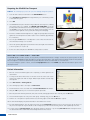
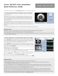
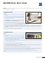
GDxPRO Quick Start Guide
CAUTION: Refer to the User Manual for warnings, safety information, labeling, and detailed operating instructions. This Reference Guide
is only a complement to the User Manual.
Setting Up the Device
NOTE:
• Do not turn the power on until all connections are made and all steps are
completed.
• Be sure to unlock the scan head optics before applying power to GDxPRO.™
System warm up and self tests will fail if the scan head optics are not
unlocked before power is applied.
1. Take the GDxPRO out of its transportation container, remove all associated
packaging, and place it on a secure examination table.
2. Connect the printer cable, keyboard and mouse to the device’s USB ports.
3. Connect the power cable to the GDxPRO, but do not plug it into the power source yet.
4. Unlock the optics box. Using the supplied Phillips head screwdriver, unscrew the transport lock on the right side of the device, turning
counterclockwise (approximately 4 to 5 full turns). The spring-loaded locking screw should be loose and turn freely when the optics box
is unlocked.
5. Only now, connect the device to the power source and turn it on.
Turning the Device On
NOTE:
• Do not turn the power on until all connections are made and all steps are
completed.
• Be sure to unlock the scan head optics before applying power to GDxPRO.
The spring-loaded locking screw should be loose and turn freely when the
optics box is unlocked. System warm up and self tests will fail if the scan
head optics are not unlocked before power is applied.
Power Cord Connector Power Switch
Fuse Holder
Ethernet Port
2 USB Ports
• If the unit is cold, allow it to adjust to normal room temperature before turning on the power. It may take up to 30 minutes for GDxPRO
to “warm up” and pass the system test.
1. The power switch is located on the bottom right side of the device.
2. Turn on the system by turning the switch to the “I” position (l = On, 0 = Off). If the switch is already in the “I” position, you must press
the yellow on/off switch on the LCD display to turn on the device.
3. Once it is turned on, the device runs through a warm up and test phase lasting several minutes.
4. After use, the device must be shut down in an orderly fashion. Turn it off by pressing the green on/off switch on the LCD display. This
switch changes from green to yellow, after which you may flip the power switch on the right bottom of the device.
N O T E : It is recommended that the device be left turned on during the day, and turned off only at the end of the workday.
2660021139635 A
1
Preparing the GDxPRO for Transport
N O T E : The following steps protect the optics from damage during transportation.
1. Leave the device turned on and return to the GDxPRO MAIN screen.
2. Select Shut Down for Transport. A message will ask you to confirm that you wish
to shut down the system.
3. Select OK.
4. The GDxPRO internal optics will start moving toward the docked position, enabling
the locking screw to be engaged. The PREPARE FOR TRANSPORT screen will
provide pictures and instructions for inserting the Phillips screwdriver, supplied with
the GDxPRO accessory kit, into the optics lock down screw hole (larger of the air
vent holes) on the right side of the system (when facing the LCD display).
5. Insert the screwdriver head through the hole, engage the spring-loaded screw, and
tighten the screw firmly with a clockwise rotation of the screwdriver (approximately
4 to 5 full turns).
6. Press the green Power button on the Operator Console. After the LCD turns off,
the Power button changes color to amber.
7. Turn off the power by flipping the power switch on the bottom right of the instrument
to the off position (I = on, O = off).
8. Remove the cables and place the GDxPRO in its transportation container.
SETTING UP OPERATOR / DOCTOR
The GDxPRO database contains operators, doctors, patients, and exams (measurements or images). You must be set up as an operator in order
to have access to GDxPRO patient and exam data. An operator will only be able to view exams and access patient records for those patients
who are assigned to a doctor associated with the operator. Operators can be associated with one or more doctors.
To set up or modify an operator or doctor, select the Set Up Operator button on the MAIN screen and follow the button options on the
subsequent screens.
Patient Information
1. Once the self test and warm up phases are completed, you will be guided to the
start window.
2. You may use the device with a mouse or via touch screen. Use of the touch screen
requires only a light touch with one finger. Written input should be entered using
the keyboard.
3. Select New Patient or Existing Patient.
4. The following steps relate to the input of a New Patient.
5. Follow instructions on the screen and enter the Patient Identification information.
6. Using the TAB key allows you to move between patient input fields.
7. Once the patient information (patient ID, name, date of birth, treating physician) has been entered, press the OK button.
8. The new window requires the entry of the ethnic group. Following entry, press the OK button.
9. Now the sex of the patient is requested. After successful entry, again confirm with the OK button (option).
10.The next window displays the patient information entered thus far for review.
11.For newly admitted patients, press the field on the lower left side (Single Exam) using the mouse or the touch screen. As an option, you
may choose the triple scan if you would like to take 3 images per eye. This increases accuracy, but also takes significantly more time.
12.You may search for Existing Patients either by patient number or last name, or by selecting View Full List and selecting from there.
The desired name will be shown with a blue background and is thus selected.
2
2660021139635 A
Pre-measurements: Determining the Refraction and the Cornea Compensation
N O T E : The following steps for AutoFocus and Cornea Compensation need to be performed only
during the first examination of the patient. They will be retrieved for all follow-up measurements, The
pre-measurements should be completely redone only for patients who have had eye surgery.
1. Ask the patient to look into the device. The patient should see the blinking fixation target in the red
field. If the patient is having difficulty seeing it, the Low Vision Target can be selected. During the
examination, the patient should lean comfortably against the face mask.
2. The screen Image Acquisition – Autofocus OD appears with the instruction Please Wait. As soon
as the Please Wait instruction disappears, the measurement may be taken.
3. The right eye is examined first. Here the fixation target of the patient is seen on the left. Move the
mouse arrow to the middle of the pupil and press the left mouse button. If you use the touch screen,
place your finger on the center of the pupil. This will facilitate rough centering. Fine adjustment can
be attained using the four arrows below the image. The pupil should then be located in the center of the yellow circle. Then move the
white snowball to the horizontal red line located to the left of the pupil. You may do this using the mouse or touch screen with the two
arrows on the lower left side. The white snowball is never absolutely sharp here.
4. Ask the patient to blink and to keep the eye open before you press Acquire.
5. Next, the Image Acquisition – Corneal Measurement OD is displayed automatically. Center the eye the same way as before by moving
the arrows via touch screen or mouse. If the patient is fixating properly, the live fundus image should be uniformly illuminated, showing
the optic nerve head close to the center of the field. Press Acquire again.
6. You have now completed the pre-measurements of the right eye. The device automatically turns to the left eye.
7. Proceed with the pre-measurements of the left eye exactly as with the right eye.
Modify Macula Ellipse – Cornea Measurement
1. After measurement of the cornea, the screen Modify Macula Ellipse appears.
2. The screen displays the macular ellipse, which the system positioned
automatically, for the respective eye, first the right side and then the left.
The ellipse or the small circle should be located in the middle of macula,
denoted by the “bow tie” pattern.
3. In addition, the optimal centering of the optical nerve is indicated with the
help of a square point line.
Dotted square indicates
optimal ONH centering.
ONH located inside the
dotted square indicates
accurate patient fixation.
Macular ellipse centered on
macula “bow tie” pattern.
N O T E : Optimal fixation of the patient is assured only when the head of the optical nerve is centered on the square point line. Consider
repeating the corneal measurement if the optic nerve head is outside the square.
4. You are now able to manually change the position of the macular ellipse with the arrow keys.
5. To achieve this, various buttons on the lower edge of the image (in the form of arrow keys) are available to you.
6. By pressing the OK button, you will move to the left eye, and proceed in the same fashion.
Image Quality
1. After optimizing the placement of the macular ellipse for both eyes, the Image Check –
Measuring Cornea Screen automatically appears on the device screen.
2. A good image has been obtained when the point score for the evaluation is 7 or higher (maximum 10). If necessary, Retake Image if this score is not high enough. You may select among
Retake Right Eye, Retake Left Eye, or Retake Both Eyes.
3. In addition, an OK sign for alignment, fixation, refraction, or other (causes) must be visible.
4. To be able to leave this menu, press the button for OK or Accept.
N O T E : In some cases and for some eyes, it will not be possible to achieve the recommended score value and avoid all quality messages.
Refer to the Troubleshooting Guide in the User Manual for more information. Accept the best scan that can be obtained.
2660021139635 A
3
The RNFL Scan (“Acquisition – ECC”)
1. Once the quality of the corneal compensation measurement has been displayed and accepted, you will move to the RNFL scan,
where the structures and condition of the retinal nerve fiber layer are analyzed. The scan mode will be indicated in the title bar as
Acquisition – ECC.
2. The RNFL measurement procedure is identical to the Cornea Measurement described above. Once again, you will first analyze the
right eye, and then the left.
Image Quality Check for RNFL Structures
2. Select Modify ONH Ellipse for the right and the left eyes.
3. You are now in the Modify Ellipse mode. Make sure that the ellipse is correctly positioned
on the edge of the papilla (Position of the ONH Ellipse).
4. To center the pupil, you have four positioning buttons available (Left, Right, Up, Down) to
move around. You may also adjust the Size of the ONH Ellipse (form and size).
ONH ellipse well centered
5. Once the ellipse for both eyes has been placed in the center of the optical nerve head and
confirmed with the OK button, you will be guided to the window displaying the results of
the analysis.
6. Now you have the opportunity to store and print out the examination results by selecting
Print and pressing OK once.
7. The screen Review Calculations – ECC delivers a summary of the examination results, a
display of the TSNIT diagram, an illustration of the nerve fiber layer, and the corresponding
parameter table.
8. Pressing Cancel will take you back to the start page.
ADDITIONAL RESOURCES: www.meditec.zeiss.com/gdxpro
If you need further assistance, please contact Customer Service at 1-800-341-6968 (USA) or your local Carl Zeiss Representative.
Carl Zeiss Meditec, Inc., Dublin, CA 94568 USA
4
2660021139635 A
Carl Zeiss Meditec AG, 07740 Jena, Germany
GDX.2965
The contents of the guide may differ from the current status of approval of the product in your country. Please contact your regional representative for more information.
Subject to change in design and scope of delivery and as a result of ongoing technical development. © 2010 Carl Zeiss Meditec, Inc. All copyrights reserved. GDxPRO, and
GDx are either registered trademarks or trademarks of Carl Zeiss Meditec, Inc. in the United States and/or other countries. Printed in USA. 0810 XM
1. When the RNFL image acquisition is completed, the Image Check – ECC screen is displayed
and should be reviewed before accepting the scan.