1
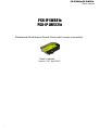
PCX-IP LW881e, PCX-IP LW1221e User’s manual PCX-IP LW881e PCX-IP LW1221e Professional Multichannel Sound Cards with Livewire connectivity User’s manual Version 1.00 April 2013 1 PCX-IP LW881e, PCX-IP LW1221e User’s manual For technical support, please contact your system supplier. Digigram S.A. Parc de Pré Milliet, 38330 Montbonnot FRANCE Tel: +33 (0)4 76 52 55 01• Fax: +33 (0) 4 76 52 53 07• Email: [email protected] Digigram Asia Pte Ltd. 60 Albert Street #1911OG Albert Complex Singapore 189969, Singapore Tel : +65 6291 2234 • Fax : +65 6291 3433 • Email : [email protected] 2 PCX-IP LW881e, PCX-IP LW1221e User’s manual Table of Contents INFORMATION FOR THE USER IMPORTANT NOTICE FEATURES PCXIP LW881 main hardware features PCXIP LW1221 main hardware features Main software features REQUIREMENTS Supported operating systems Minimum hardware requirements Software requirements HARDWARE INSTALLATION Installing the card Interrupt and memory address SOFTWARE INSTALLATION Standard installation XTopology installation ASIO driver configuration Wave driver configuration Removing the driver HOW TO CHECK THE INSTALLATION THE “DHS” CONTROL PANEL CONFIGURATION OF LIVEWIRE PARAMETERS Configuration of sources Configuration of destinations Configuration of GPIOs Vu_meters Qos System parameters 3 PCX-IP LW881e, PCX-IP LW1221e User’s manual SPECIFICATIONS Configuration Inputs/Outputs Sampling frequency Connectors Development environments & supported operating systems APPENDICES Schematic diagrams GPIOs connector pinout 4 PCX-IP LW881e, PCX-IP LW1221e User’s manual INFORMATION FOR THE USER This device complies with part 15 of FCC rules. Operation is subject to the following two conditions: (1) This device may not cause harmful interference, and (2) This device must accept any interference received, including interference that may cause undesired operation. This equipment has been tested and found to comply with the limits for a CLASS B digital device, pursuant to Part 15 of the FCC Rules. These limits are designed to provide reasonable protection against harmful interference in a residential installation. This equipment generates, uses, and can radiate radio frequency energy and, if not installed and used in accordance with the instructions contained in this data sheet, may cause harmful interference to radio and television communications. However, there is no guarantee that interference will not occur in a particular installation. If this equipment does cause harmful interference to radio or television reception, which can be determined by turning the equipment off and on, the user is encouraged to try to correct the interference by one or more of the following measures: * reorient or relocate the receiving antenna * increase the separation between the equipment and the receiver * connect the equipment into an outlet on a circuit different from that of the receiver * consult the dealer or an experienced audio television technician. Note: Connecting this device to peripheral devices that do not comply with CLASS B requirements or using an unshielded peripheral data cable could also result in harmful interference to radio or television reception. The user is cautioned that any changes or modifications not expressly approved by the party responsible for compliance could void the user’s authority to operate this equipment. To ensure that the use of this product does not contribute to interference, it is necessary to use shielded I/O cables. Warning: Electrostatic discharge (ESD) can damage several components on the board. To avoid such damage in handling the board, take the following precautions: Bring the device and everything that contacts it to ground potential by providing a conductive surface and discharge paths. As a minimum, observe these precautions: ● ● ● ● Disconnect all power and signal sources. Place the device on a grounded conductive work surface. Ground yourself via a grounding wrist strap or by holding a grounded object. Ground any tool that will contact the device. Due to the reduced length of the PCI EXPRESSTM bus connector and the resulting lack of mechanical stability, we strongly advise against transporting the PCIe® card(s) installed in a computer, unless its chassis or case provides a dedicated support to keep the card securely in place in order to avoid physical damage. IMPORTANT NOTICE This card has been tested and found to comply with the following standards: ● International: CISPR22 Class B ● Europe: EMC 89/336/CEE (1992) specifications ● United States: FCC RulesPart 15Class B (digital device) In order to guarantee compliance with the above standards in an installation, the following must be done: ● the provided cable must not be modified ● additional cables used must have their respective shield connected to each extremity 5 PCX-IP LW881e, PCX-IP LW1221e User’s manual FEATURES PCXIP LW881e and PCXIP LW1221e are sound cards for use with Axia Livewire™ systems, with PCI EXPRESSTM (PCIe®) bus interface. They are in PCI EXPRESSTM x1 format and can thus be plugged into any PCIe® slot (x1, x4, x8, x16). PCXIP LW881 main hardware features ● 1 RJ45 Ethernet port allowing for extraction of up to 8 mono channels from the Livewire network, and insertion of up to 8 mono channels in the Livewire network ● 1 SubD 9 pin connector for 5 physical GPI / 5 physical GPO transmitted through the Livewire network. ● 48 kHz sampling frequency ● Several cards can be plugged in one PC PCXIP LW1221 main hardware features ● 1 RJ45 Ethernet port allowing for extraction of up to 2 mono channels from the Livewire network, and insertion of up to 12 mono channels in the Livewire network ● 1 SubD 9 pin connector for 5 physical GPI / 5 physical GPO transmitted through the Livewire network. ● 48 kHz sampling frequency ● Several cards can be plugged in one PC Main software features ● Realtime, simultaneous record and playback in PCM (8, 16 and 24 bits) as well as in MPEG Audio Layer I, Layer II and Layer III*, Float IEEE754 conversion supported (with 24bit fixedpoint dynamic range) ● When using the Digigram np SDK, realtime mixing of several PCM and MPEG audio streams per output channel, direct monitoring, ● * level adjustment, panning, crossfades, punchin/punchout, scrubbing, timestretching, pitchshifting, 3band parametric equalizer, Maximizer, format and frequency conversions. Low latency WDM DirectSound, Wave, and ASIO drivers. Under DirectSound and ASIO, the cards operate in PCM mode only (nevertheless, an application can integrate coders/decoders on the host PC). Under Wave, HR boards can operate in both PCM and MPEG (layer 1 and layer 2). MPEG Layer III playonly on DSP MPEG Layer III recording on the host computer is available through Digigram’s PC Codec using the np SDK 6 PCX-IP LW881e, PCX-IP LW1221e User’s manual REQUIREMENTS Supported operating systems PCX Livewire cards run under the following operating systems: ● 32bit OS: Windows XP, Windows Server 2003, Windows Vista, Windows Server 2008, Windows 7, Windows 8 ● 64bit OS: Windows Server 2008, Windows 7, Windows 8. Minimum hardware requirements One PCI EXPRESS™ (PCIe®) slot per card (x1, x4, x8, x16). Required CPU power and memory mainly depend on the operating system and on the audio application used. Software requirements To use your card under Windows, please install the driver from the HR Runtime package version 1.74 or higher. This package includes: ● a Digigram np driver enabling OEM applications to best capitalize on the onboard features (MPEG, mixing, timescaling, crossfades,...). ● a WDM DirectSound driver (32 bits or 64 bits according to the OS) ● a Wave driver (32 bits, installation optional) ● an ASIO driver (32 bits and 64 bits, installation optional) 7 PCX-IP LW881e, PCX-IP LW1221e User’s manual HARDWARE INSTALLATION Due to the reduced length of the PCI EXPRESS™ bus connector and the resulting lack of mechanical stability, we strongly advise against transporting the PCIe® card(s) installed in a computer, unless its chassis or case provides a dedicated support to keep the card securely in place in order to avoid physical damage. The card has to be installed in the computer prior to installing its driver. Installing the card Gently plug the card in a free PCI slot and press it down to position it firmly. Tighten the screw. Interrupt and memory address Hardware interrupt and addresses are automatically set up at startup by the PCI PnP BIOS. 8 PCX-IP LW881e, PCX-IP LW1221e User’s manual SOFTWARE INSTALLATION The installation of the driver package requires administrator rights on your computer. Please visit the Digigram web site at www.digigram.com for the most recent driver. In case you run a specific application developed or installed by a Digigram Partner, this application might require the use of a specific driver version. In this case, make sure that the updated driver has been approved by your supplier. The following procedure installs the ‘Digigram Hardware Settings’ control panel. This application allows the configuration of the hardware resources of Digigram cards for all audio applications. The DHS allows for instance to adjust input and output digital gains and direct monitoring of inputs on ouputs. With the inputs and outputs are controlled through the DHS application, the controls available through the DirectSound control panel get invalid : ● Volume control for input ● Volume control for output Standard installation ● ● ● ● Shut down your computer and insert your PCX card. Restart your computer. Click on Cancel if the “Found New Hardware Wizard” appears. Doubleclick on the HR Runtime driver package icon to launch the driver installation. A welcome message is displayed, click Next to continue. The “License Agreement” window appears: read it, and click on “I accept the terms in the license agreement” to approve it. Do the same in the next License agreement window for Virtual PCX and PC Codec Legal Notice. 9 PCX-IP LW881e, PCX-IP LW1221e User’s manual In the “Custom Setup” window, the “Drivers for the HR boards” that can be installed are listed. The WDM DirectSound driver and the Digigram np driver are automatically installed. Items that can be optionally installed are: ● Digigram Hardware Settings panel (DHS): installed by default. The DHS control panel allows for adjusting digital level for input/ouptut channels, and monitoring parameters. These settings cannot be controlled through DirectSound controls. If the DHS is not installed, these settings are accessible for the DirectSound controls. This item is not selectable under Windows XP (see XTopology installation) ● Asio driver: installed by default ● Wave MME driver: not installed by default ● VX devices visible by default (to be selected in case the np based application is not designed to detect the VX card the use of this option is specified by your software application provider). Click on Next once you have made your selection of items to be installed. In the Window “Ready to Install the Program”, click on Install to start copying the files. In case the User Account Control window prompts you to authorize the driver installation, click on OK. Driver files are then installed on the computer. In case the “Digital Signature Not Found” message appears because a nonMicrosoft software is about to be installed, click on Continue. Click Finish to complete the driver installation. XTopology installation Under Windows XP and Windows Server 2003, it is possible to install the drivers without the DHS, so that controls like digital levels and monitoring are accessible from the DirectSound controls. The driver package must then be installed as follows: MsiExec.exe /I abcd.msi X_TOPOLOGY=1, where “abcd.msi” is to be replaced by the name of the driver package. ASIO driver configuration Note: Under 64bit operating systems, and for most current ASIO applications (e.g. Cubase, Nuendo, etc...) you have the choice between a 32bit version and a 64bit version when installing them. The 64bit package of HR Runtime installs both a 10 PCX-IP LW881e, PCX-IP LW1221e User’s manual 32bit ASIO driver and a 64bit ASIO driver. To use the ASIO driver on your PCX sound card, the option “PCM only” has to be enabled from the Digigram control panel (CPL). To access this control panel, go to <Start>, <Programs>, <Digigram>, <Digigram Control Center>. To launch the ASIO control panel, go to <Start>, <Programs>, <Digigram>, <Digigram ASIO HR Settings>. It allows to: ● set/modify the size of ASIO buffers (= latency adjustment) ● select the number of bits per sample (16, 24, 32) ● select the LTC frame rate ● select the I/Os to be used by the application(s) ● enable/disable the hardware monitoring control ● enable/disable the multiclient mode. When enabled, several applications can access different channels of the card (but one channel cannot be used by several applications) For more information on this ASIO control panel, to refer to its online help. Wave driver configuration In the case the software application exclusively manages PCM audio through the Wave MME interface, the latency of the Wave driver can be optimized by enabling the option “PCM only” in the Digigram control panel (CPL). To access this control panel, go to <Start>, <Programs>, <Digigram>, <Digigram Control Center>. For detailed information on how to use the Digigram control panel, please refer to its online help (“? Help” button). 11 PCX-IP LW881e, PCX-IP LW1221e User’s manual Removing the driver Open the Windows Control Panel and doubleclick on the Add/Remove Software icon or Programs and Features icon, depending on the Windows flavour. ● Select “Digigram HR Runtime …”, and Change/Remove. ● Select Remove in the HR Runtime window. ● Follow the instructions to finish to remove the driver. HOW TO CHECK THE INSTALLATION Once the card and the driver have been installed according to the procedure described in this manual, you can check that the PCX card is properly installed and works fine as follows. ● From <Start> <Programs> <Digigram>, select <Digigram Control Center>. ● Select the ‘General Information’ tab. In the “Modules Information” window, you can see the HR Runtime modules that have been installed, and their versions. ● Select the ‘Diagnostics’ tab to display the installed card(s). If the card is not displayed: ● Make sure that during the HR runtime installation the “Driver for the HR boards” has been selected in the “Select components” window. ● Open the Windows Device Manager (from Control Panel, System). The card should be listed in “Sound” or “Sound, video, and games” controllers. If it is listed with no warning symbol, the card is well recognized by the system. In case there is a warning symbol : make sure that the card is correctly inserted in the PCI slot, and screwed on the PC chassis. ● If necessary, uninstall the HR runtime package as described in this manual, and reinstall it. If the card is displayed: ● Right click on the icon of the card. ● Select ‘Diagnostics’, and ‘Play Sine’. This plays in loop a sine signal on all the output channels of the card. You can also select ‘Play file’ to play in loop a file of your choice (PCM only). If the playback is correct, the card is correctly installed and works. ● To stop the playback, right click on the card icon, and select ‘Stop Activities’. The DirectSound devices associated to the card are displayed from the Windows Control Panel, Sound. ● Select tab “Audio”, Default device (Playback device, Recording device). Available DirectSound devices that can be selected from a DirectSound application are: DirectSound playback devices 12 DirectSound recording devices PCX-IP LW881e, PCX-IP LW1221e User’s manual OUT 1+2 (Digigram PCXIP LW881e) / OUT 1+2 (Digigram PCXIP LW1221e) OUT 3+4 (Digigram PCXIP LW881e) / OUT 3+4 (Digigram PCXIP LW1221e) OUT 5+6 (Digigram PCXIP LW881e) / OUT 5+6 (Digigram PCXIP LW1221e) OUT 7+8 (Digigram PCXIP LW881e) / OUT 7+8 (Digigram PCXIP LW1221e) OUT 5.1 (Digigram PCXIP LW881) / OUT 9+10 (Digigram PCXIP LW1221e) OUT 7.1 (Digigram PCXIP LW881) / OUT 11+12 (Digigram PCXIP LW1221e) / OUT 5.1 (Digigram PCXIP LW1221e) / OUT 7.1 (Digigram PCXIP LW1221e) / OUT 5.1+2 (Digigram PCXIP LW1221e) IN 1+2 (Digigram PCXIP LW881) / (Digigram PCXIP LW1221e) IN 3+4 (Digigram PCXIP LW881) IN 5+6 (Digigram PCXIP LW881) IN 7+8 (Digigram PCXIP LW881) IN 5.1 (Digigram PCXIP LW881) IN 7.1 (Digigram PCXIP LW881) IN 5.1+2 (Digigram PCXIP LW881) If the Wave driver has been installed, and for OS older than Windows 7: ● Go to menu <Start>, <Settings>, <Control panel>, <Sound and Multimedia>, tab “Audio”, Default device (Playback device, Recording device). The card’s channels can be selected. The card can be used with any Wave application. Available Wave MME devices that can be selected from a Wave MME based application are: Wave playback devices PCXIP LW881e (Wave) / PCXIP LW1221e (Wave) PCXIP LW881e (Wave) / PCXIP LW1221e (Wave) PCXIP LW881e (Wave) / PCXIP LW1221e (Wave) PCXIP LW881e (Wave) / PCXIP LW1221e (Wave) PCXIP LW881e 5.1 (Wave) / PCXIP LW1221e (Wave) PCXIP LW881e 7.1 (Wave) / PCXIP LW1221e (Wave) PCXIP LW881e 5.1+2 (Wave) / PCXIP LW1221e 5.1 (Wave) / PCXIP LW1221e 7.1 (Wave) / PCXIP LW1221e 5.1+2 (Wave) / PCXIP LW1221e 7.1+2 (Wave) Wave recording devices PCXIP LW881e (Wave) / PCXIP LW1221e (Wave) PCXIP LW881e (Wave) PCXIP LW881e (Wave) PCXIP LW881e (Wave) PCXIP LW881e 5.1 (Wave) PCXIP LW881e 7.1 (Wave) PCXIP LW881e 5.1+2 (Wave) When opening the Digigram Wave Mixer application, only one vumeter is displayed on the selected channel mixer. If the ASIO driver has been installed, the card is visible from the ASIO control panel, and from any ASIO application. To launch the ASIO control panel, go to <Start>, <Programs>, <Digigram>, <Digigram ASIO HR Settings>. 13 PCX-IP LW881e, PCX-IP LW1221e User’s manual 14 PCX-IP LW881e, PCX-IP LW1221e User’s manual THE “DHS” CONTROL PANEL Digigram Hardware Settings (DHS) is an application allowing to configure the hardware resources of Digigram cards for all audio applications using them. The parameters of an resource being managed by the DHS application can not be modified from another applications. To enable an audio application to modify a Digigram card resource, this resource must not be managed by the DHS. Note: As soon as a resource of a card is managed by the DHS, the clock selection of this card must be defined in the DHS. The DHS allows to: ● adjust digital gains of input and output signals ● mute / unmute input and output signals ● Select the input monitored on an output (zero latency hardware monitoring) ● Set the monitoring gains For more detailed information on how to use this control panel, please refer to its online help. 15 PCX-IP LW881e, PCX-IP LW1221e User’s manual CONFIGURATION OF LIVEWIRE PARAMETERS To be able to configure the Livewire parameters from the WEB pages of the PCX card, it is necessary to connect a NIC card of the computer to the Livewire network. The PCX card default IP address is: 192.168.0.100. Enter this IP address in your WEB browser address bar. A username is required to access the WEB pages. Username: user No password The following page is displayed. Configuration of sources Configuring Livewire sources is necessary to assign the playback devices of the PCXIP to Livewire inputs. PCXIP 881e features 8 mono playback devices to be injected to 8 Livewire mono inputs. PCXIP 1221e features 12 mono playback devices to be injected to 12 Livewire mono inputs. To configure the Livewire sources, click on “Livewire Sources”. The following page is displayed. From this page, you can : ● Give a name to each local input to the Livewire node: Source Name (16 printable characters max). This can typically be the name given to a channel of a playback application running on the PCXIP card (ex: PCXIP Player 1). ● Assign a livewire channel to each source: Channel. The channel number must be unique, and between 1 and 32767. ● Set parameters for each source: Shareable: Stream Mode: Select “Live Stereo” for streams where low latency is required, and select “Standard Stereo” otherwise. Configuration of destinations Configuring Livewire Destinations is necessary to assign the recording devices of the PCXIP to the Livewire outputs. PCXIP 881e features 8 mono recording devices receiving 8 Livewire mono outputs. PCXIP 1221e features 2 mono recording devices treceiving 2 Livewire mono outputs. 16 PCX-IP LW881e, PCX-IP LW1221e User’s manual To configure the Livewire Destinations, click on “Destinations”. The following page is displayed. From this page, you can : ● Give a name to each local output to the Livewire node: Name (16 printable characters max). This can typically be the name given to a channel of a recording application running on the PCXIP card (ex: PCXIP Rec1). ● Select one of the available Livewire channels to be extracted and assign to the corresponding PCXIP input. ● Set the Type for each selected livewire channel: From source: To source: Configuration of GPIOs Vu_meters This page displays the vumeters of the signals available on the Livewire sources (typically audio coming from software players) and destinations (typically Livewire channels to be recorded by software recorders). Click on “Meters” to display the vumeters page. 17 PCX-IP LW881e, PCX-IP LW1221e User’s manual Qos In most of the cases, the parameters of the “QoS” page should not be changed. In case you need to modify them, you may refer to documents available from Axia WEB site. System parameters The “System” page allows setting the network parameters of the PCXIP card. These parameters are the usual parameters of a network interface like: ● Host name: used to identify the PCXIP card on the network. ● Network address: IP address of the PCXIP card on the network. There must be no other node with the same IP address. ● Netmask: mask to identify the sub network the nodes belongs to ● .... 18 PCX-IP LW881e, PCX-IP LW1221e User’s manual SPECIFICATIONS Configuration PCXIP LW881e / PCXIP LW12121e Bus/Format PCI Express™ (PCIe x1) (x2, x4, x8, x16 compatible) Size 168 mm x 111 mm x 20 mm Power requirements (+3.3V/+5V / +12V / –12V) 2.5 A / 0 A / 0.1 A / 0 A Operating: temp / humidity (noncondensing) 0°C/+50°C . 5%/95% Storage: temp / humidity (noncondensing) 5°C/+70°C . 0%/95% Inputs/Outputs PCXIP LW881e PCXIP LW12121e Livewire input mono channels 8 2 Livewire output mono channels 8 12 Programmable input/output digital gain General Purpose Inputs & Outputs from –110 dB à +18 dB from –110 dB à +18 dB 5 5 Sampling frequency Sampling frequencies available 48 kHz Connectors Ethernet GPIO RJ45 SubD 15 pins Development environments & supported operating systems Digigram management Other APIs OS supported np SDK (HR Runtime, PCM & MPEG) DirectSound, DirectKS (PCM) ASIO (PCM) Wave1* (PCM & MPEG Layer I & II) Windows 8, Windows 7,Windows XP, Windows Server 2003, Windows Se rver 2008 APPENDICES 1 * Windows XP and Server 2003 only; for Windows Vista, a Wave driver is available on request. 19 PCX-IP LW881e, PCX-IP LW1221e User’s manual Schematic diagrams GPIOs connector pinout The pinout of the GPIOs on the SubD 15 pinconnector of the PCX card is identical to the GPIO connector used in Axia nodes. 20