1
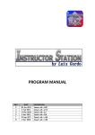
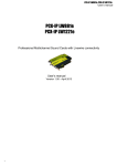
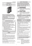
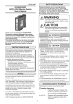
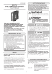
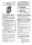
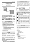
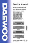
No. CP-UM-1221E
SIA, SIB, SIC, SID
Smart Indicator
with LED Bar Graph
User's Manual
Thank you for purchasing the SIA, SIB,
SIC and SID.
This manual contains information for
ensuring the correct use of the SIA, SIB,
SIC and SID. It also provides necessary
information for installation, maintenance, and troubleshooting.
This manual should be read by those
who design and maintain equipment
that uses the SIA, SIB, SIC and SID. Be
sure to keep this manual nearby for
handy reference.
RESTRICTIONS ON USE
This product has been designed, developed and manufactured for general-purpose
application in machinery and equipment.
Accordingly, when used in applications outlined below, special care should be taken to
implement a fail-safe and/or redundant design concept as well as a periodic
maintenance program.
• Safety devices for plant worker protection
• Start/stop control devices for transportation and material handling machines
• Aeronautical/aerospace machines
• Control devices for nuclear reactors
Never use this product in applications where human safety may be put at risk.
NOTICE
Be sure that the user receives this manual before the product is used.
Copying or duplicating this user’s manual in part or in whole is forbidden. The information and specifications in this manual are subject to
change without notice.
Considerable effort has been made to ensure that this manual is free
from inaccuracies and omissions. If you should find an error or omission, please contact Yamatake Corporation.
In no event is Yamatake Corporation liable to anyone for any indirect,
special or consequential damages as a result of using this product.
©1998 Yamatake Corporation ALL RIGHTS RESERVED
CONTENTS
1. GENERAL . . . . . . . . . . . . . . . . . . . . . . . . . . . . . . . . . . . . . . . . . . . . . . . . . . .1
2. DIMENSIONS AND INSTALLATION . . . . . . . . . . . . . . . . . . . . . . . . . . . . . . .2
3. WIRING . . . . . . . . . . . . . . . . . . . . . . . . . . . . . . . . . . . . . . . . . . . . . . . . . . . . .3
4. ALARM SETTING AND ZERO-SPAN ADJUSTMENT . . . . . . . . . . . . .4 to 5
5. SPECIFICATIONS AND MODEL NUMBERS . . . . . . . . . . . . . . . . . . . . . . . .6
1. GENERAL
The Smart Indicator is a compact, lightweight, highly reliable, DIN-compatible LED bar graph indicator for process
monitoring.
Features
• Bar graph with high-intensity custom LEDs.
• Three bar display colors: red, green and yellow, selectable.
• Easy alarm setting and zero span adjustment from the front panel.
2. DIMENSIONS AND INSTALLATION
1. External dimensions
Unit : mm
Unit identification
and number (nameplate)
Mounting spacer
160
139
144
138.1
16
135
Fig.2
Fig.1
Mounting spacer
Side
9.4
144
9
36
Front
7.5
35
138.1
41
2. Panel dimensions
3. installation of panel
Fixing bracket
Installation of single unit
Mounting spacer
Side-by-side close mounting
(36 X N) +10 +1
Mounting spacer
Over 190
Over 190
139.5 +10
139.5 +10
35.5 +10
Fig.4
N: No. of units mounted.
No. of mounting spacers:
One spacer on each side of panel,
either for single-unit or multi-unit installation.
Fixing bracket
Nameplate
Mounting screw
Fig.3
Fig.5
1
4. Panel mounting method
(1) Attach the included mounting spacers to the right and left sides of the instrument body.
(2) Insert the instrument body into the panel cutout.
(3) Mounting screws are located at the top and bottom behind the two nameplates. With a phillips head screwdriver,
turn the screws clockwise to raise the fixing bracket the secure the instrument body in place.
(4) To remove the instrument from the panel, simply turn the screws counterclockwise.
5. Choose installation
Choose a location that meets the following requirements:
Operating conditions
Ambient temperature: SIA, SIB: 0 to 50°C
SIC, SID: 0 to 45°C
Ambient humidity:
80% RH at 40°C
Vibration resistance:
4.9m/s2 (10 to 60Hz)
Shock resistance:
490m/s2
Cautions
• Do not mount the instrument in an environment where these is flammable gas.
• Do not use the instrument in a highly corrosive atmosphere.
• Distance the instrument from any potential source of electrical interference: large-capacity electromagnetic
switches, high-frequency generating units, SCR units, or the like.
3. WIRING
1. Cables
(1) For the input signal, use a shielded cable suitable for measuring-instrument use.
(2) Use a 600V vinyl insulated cable (IV cable) conforming to JIS C3307 for the 100/110Vac power supply.
Cautions
• Leave space of more than 50cm between the input signal cable and the power line.
• Do not run the input signal cable and the power line in the same conduit, or in close proximity.
• Distance the input signal cable from the power, high voltage and load lines.
• The above conditions also apply to internal panel wiring.
2. Terminal connection
(1) Use solderless terminals that take M3 screws.
(2) The instrument is not equipped with a power switch. Mount one separately, if necessary.
(3) Connect wiring according to the terminal connection diagram. Make sure that the cables have been connected
correctly.
Terminal connection diagram
SIA type
1
SIB type
SIC type
1
Input
SID type
1
Input No.1
Input
2
2
3
3
3
Hc
4
4
4
Ha
5
Hb
2
5
6
7
8
Input No.2
Power supply
24Vdc
Power supply
100V/110V
200V/220V
AC 50/60Hz
120V
240V
5
6
7
8
Power supply
24Vdc
Power supply
100V/110V
200V/220V
AC 50/60Hz
120V
240V
1
Input
2
3
H(H)c
4
HHa
5
HHb
6
6
Ha
7
7
La
8
LLa
8
La
9
Lb
10
Lc
11
12
H side output
L side output
Power supply 24Vdc
100V/110V
200V/220V
AC 50/60Hz
120V
240V
( )Polarilty of 24Vdc power supply
2
9
LLb
10
L(L)c
11
HH side
output
H side output
LL side
output
L side output
Power supply 24Vdc
100V/110V
200V/220V
AC 50/60Hz
120V
240V
( )Polarilty of 24Vdc power supply
12
4. ALARM SETTING AND ZERO SPAN ADJUSTMENT
1. Location
For SIA and SIB types:
The zero and span control knobs are accessible by removing the nameplates, acrylic cover and scale plate.
Adjust the knobs according to the instructions in Section 4.3.
For SIC and SID types:
First remove the nameplates and acrylic cover. Set the alarm and adjust the zero and span knobs according to the
instructions in Section 4.3.
SIA and SIB types
SIC and SID types
Span control knob
Nameplate
Acrylic
cover
Scale plate
Zero control knob
Alarm setting/zero-span adjustment
Fig.7
2. Alarm setting (SIC and SID)
2-1 Setting/indicating
SET
Set point operation button
High-high-limit set point
Flashes during high-high-limit setting. Lights up during relay action.
Flashes during high-limit setting. Lights up during relay action.
High-limit set point
Light up during PV input span adjustment.
Light up during PV indicating value clear (erase).
Low-limit set point
Light up during PV input zero adjustment.
Flashes during low-limit setting. Lights up during relay action.
Low-low-limit set point
Flashes during low-low-limit setting. Lights up during relay action.
Moves set point up.
PV indicating value
Mode selector button. Modes change in direction of arrow, when button is pushed.
Moves set point down.
Fig.8
2.2 Selection of setting modes
(1) When the M mode selector button is pushed, all LEDs either flash or light up and a setting mode can be
selected.
(2) LL, L, H, and HH LEDs ( ) flash during mode selection and light up during relay action.
(3) When the
or
button is pushed, the setting mode shifts upward or downward. For rapid mode
shifting, push and hold for at least 3 seconds.
(4) The PV indicating value can be erased by selecting the PV indicating value clear mode.
2.3 Setting of high-limit (H) and high-high limit (HH)
(1) Select either the high-limit (H) or high-high limit (HH) mode by pushing
(2) Set either a high or high-high limit value by moving the setting bar up
(3) Load a set point by pushing SET . The LED should go out.
3
M. The LED should flash.
or down
.
2.4 Setting of low-limit (L) and low-low limit (LL)
(1) Select either the low-limit (L) or low-low limit (LL) mode by pushing
(2) Set either a low or low-low limit value by moving the setting bar up
(3) Load a set point by pushing SET. The LED should go out.
M. The LED should flash.
or down
.
2.5 About the hysteresis of the alarm contacts
The hysteresis of the SIC and SID is different from the operating differential of a general temperature controller.
It goes through the process described below.
(For a high-limit alarm)
(1) When the set point = the PV value, the relay contact turns ON.
(2) In the next instant, the internal set point decreases 5% FS.
(3) After 100ms, the internal set point increases 0.5% FS from the above (2) state, and comparison is made
between the internal set point and the PV value. If the internal set point > PV value, the contact turns OFF.
(4) Afterwards, at 100ms intervals, the internal set point increases every 0.5% up to the value of (internal set point
—1.0% FS), and each time the internal set point is compared to the PV value. If the internal set point > the PV
value, the contact turns OFF.
(5) At 1000ms, the internal set point returns to the original set point.
When SP > PV value, the contact turns OFF.
(1)At next instant
SP
(2)
After 100ms (3)
SP
SP
4.5%FS
5%FS
ON
After 1000ms (5)
SP
1.0%FS
Internal SP
SP
Internal SP
Internal SP
Contact
After 800ms (4)
ON
ON
ON
OFF
Note: For a low-limit alarm, the process is reversed.
3. Zero and span adjustment
For SIA and SIB types:
Span control knob:
Adjust the knobs to the desired value.
Value increases when knob is turned
clockwise and decreases when knob
is turned counterclockwise.
Zero control knob:
Fig.9
For SIC and SID types:
(1) Zero adjustment (See Fig.8)
1. Select the zero adjusting mode (Z) by pushing M. The Z lamp should flash.
2. Set the desired value by moving the PV indicating bar up or down with
or
3. Load a set point by pushing SET. The LED should go out.
(2) Span adjustment (See Fig.8)
1. Select the span adjusting mode (S) by pushing M. The S lamp should flash.
2. Set the desired value by moving the PV indicating lever up or down with
or
3. Load a set point by pushing SET. The LED should go out.
4
.
.
5. SPECIFICATIONS AND MODEL NUMBERS
Model
Input
Model No.
No. of indicating
points
Alarm
Input type
Response speed
Input impedance
Indication
Input adjustment
range
Indication method
Number of bar dots
Effective scale
length
Indication range
Indication accuracy
Alarm setting Setting range
unit
(SIC and SID)
Setting accuracy
Output and rating
SIA
1
SIB
2
SIC
1
SID
1
–
–
High/low limit
High-high limit/
low-low limit
Current: 4 to 20mA, and 0 to 1mAdc.
Voltage: 0 to 1Vdc, and 0 to 5Vdc.
0.5s (90% response)
4 to 20mA input: 10Ω. 0 to 1mAdc input: 200Ω.
1 to 5Vdc, 1 to 5Vdc and 0 to 5Vdc: 1MΩ.
±10% FS (for both ZERO and SPAN)
Red, green or yellow LED bar dots (color selectable)
Flashing display (SIA and SIB only) when input is complete.
101
100mm
0 to 100% FS
±1% FS ±1 digit
High/low
High limit value (H): 100% FS to (low limit value +1% FS)
limit
Low limit value (L): (high limit value -1% FS) to 0%
High-high High-high limit value (HH): 100% FS to (high limit value +1% FS)
limit/low-low High limit value (H): (high-high limit value -1% FS to (low limit value
limit
+1% FS)
Low limit value (L): (high limit value -1% FS) to (low-low limit value
+1% FS)
Low-low limit value (LL): (low limit value -1% FS) to 0%
±1% FS ±1 digit
Non-voltage contact (SIC: 2C, SID: 2c+2a), 125Vac 0.5A and 30Vdc 2A (resistive
load). Contact life: 500,000 cycle min. (at rated load).
Settings are safely stored in nonvolatile RAM.
Power failure
compensation
Ambient
0 to 50°C
temperature
General
Power consumption AC power: 5VA
AC power: 5VA
24Vdc power: 2W 24Vdc power: 4W
specifications Insulation
50MΩ min. by DC500V megger
resistance
between circuit and case
Dielectric strength
2000Vac for 1 min between circuit and
case.
AC power: 1500Vac for 1 min
between power and input terminal.
24Vdc power: 500Vac for 1 min between
power and input terminal.
500Vac for 1 min between input No. 1
and input No. 2.
Mass (weight)
Vibration resistance
Shock resistance
Case and cover
materials
Standard color
Additional
treatment
Mounting
Mounting angle
Standard
accessories
Selectable
0 to 45°C
10MΩ min. by DC500V megger
between circuit and case
1500Vac for 1 min between circuit and
case.
AC power: 1500Vac for 1 min between
power and input terminal.
24Vdc power: 1500Vac for 1 min
between power and input terminal,
between output contact and case,
between output contact and power, and
between output contact and circuit.
Approx. 400g
Approx. 500g
Approx. 590g
4.9m/s2 max. (10 to 60Hz)
490m/s2 max.
Case: ABS resin. Cover: acrylic resin.
Nameplate: ABS resin.
Scale: black colored aluminum.
Bezel and case: moss green (Munsell 2.5GY3/1).
Flush-mounted on indoor panel
0 to 90° (in any direction)
Mounting spacers (2 units)
With inspection certificate and/or tropicalization
5
SI Series Model Selection Guide
Model
I
I
II
III
IV
II
V
VI
III
Basic Model Power Supply
Number
Voltage
Input
IV
V
VI
No.1 Display No.1 Display No.2 Display No.2 Display Additional
Colour
Range
Colour
Range
Processing
SIA
SIB
SIC
SID
1 display
2 displays
1 display High/low limit alarm
1 display High-high limit/
low-low limit alarm
100V/110Vac 50/60Hz
200V/220Vac 50/60Hz
120Vac 50/60Hz
40Vac 50/60Hz
24Vdc
4 to 20mAdc
0 to 1mAdc
0 to 1Vdc
1 to 5Vdc
0 to 5Vdc
Red
Green
Yellow
1
2
5
6
8
C
F
L
V
Y
R
G
Y
See Range Code select Table
R
G
Y
Red
Green
Yellow
See Range Code select Table
—
D
T
B
Y
None
Inspection certificate provided
Tropicalization treatment
Tropicalization treatment +
Inspection certificate provided
Complying with the traceability
certification
Range Code select Table
Description
A
C
D
H
I O X Y Z U S T V W
m3/h[N] % m3/h l/min °C pH m mm - ppmhPa Pa kPa MPa Mantissa
Model
1
2
3
4
5 6 7 8 9 A B C D
E
F G H I
J
1
2
3
4
5 6 7 8 9 15 25 35 4 55 65 75 85 95 14
Index
Model
7
8
9
0
1 2 3 4 5 6 10-3 10-2 10-1 100 101 102 103 104 105 106 Hi/Lo
Model
X
W
Range limits
When the low limit value of the range is 0
When the range is “- (low limit value) to +
(high limit value)”. However, the absolute
high and low limit values must be the same.
Unit
Selection
Model
Example:
(1) SIA 8 C R A32X T
(2) SIB 8 C R A32X G S50W T
3
Range:
Range: 0 to 300 Nm /h
3 x10
2
A (Unit)
3 (Mantissa)
2 (Index)
X (0 low limit)
5
hPa
5 x10
0
S (Unit)
5 (Mantissa)
0 (Index)
W ( limit)
Specifications are subject to change without notice.
Advanced Automation Company
1-12-2 Kawana, Fujisawa
Kanagawa 251-8522 Japan
URL: http://www.azbil.com
Printed on recycled paper.
(07)
Printed in Japan.
1st Edition: Issued in July 1998
7th Edition: Issued in May 2007 (M)