1
COMMANDbatch
Fieldbus Controller
Setup Guide
Last Updated
10/19/15
COMMANDbatch V1.8.1.0 & Later
© 2003-2015 Command Alkon Incorporated. All rights reserved.
The contents of this document are for informational purposes only and are subject to
change without notice. Command Alkon Incorporated ("CAI") may, without notice, modify
its products in a way that affects the information contained in this publication.
CAI HEREBY DISCLAIMS ALL REPRESENTATIONS OR WARRANTIES EITHER EXPRESSED
OR IMPLIED, INCLUDING WITHOUT LIMITATION ANY IMPLIED WARRANTY OF
MERCHANTABILITY, TITLE, NON-INFRINGEMENT, OR FITNESS FOR A PARTICULAR
PURPOSE. In no event will CAI be liable for any direct, indirect, or consequential damages
arising out of the use of, inability to use, or implementation of any information contained
in this publication, even if CAI has been advised of the possibility of such damages, or for
any claim by any other party.
The information contained herein is subject to change without notice and may contain
inaccuracies or errors. CAI assumes no responsibility for any errors that may appear in
this document. This publication is intended only for the direct benefit of authorized users
of CAI products. This publication may not be used for any purposes other than those for
which it is provided, and it is subject to the terms of the applicable software license or
subscription agreement. This publication and the information disclosed herein is the
property of CAI, and, except for rights granted by written consent, may not be disclosed,
disseminated, or duplicated in whole or in part.
Command Alkon Incorporated
1800 International Park Drive, Suite 400
Birmingham, AL 35243-4232
1 (205) 879-3282
www.commandalkon.com
Main Customer Support Phone Number: 1 (800) 624-1872
COMMANDseries (and the names of its components, such as COMMANDconcrete and
COMMANDnetwork), Spectrum, Eagle, and COMMANDbatch are registered trademarks of
Command Alkon Incorporated. All rights reserved.
Microsoft and Windows are trademarks of Microsoft Corporation. Other names may be
trademarks of their respective owners.
2
10/19/15
Contents
Contents
........................................................................................ 3
Introduction
.................................................................................. 4
Purpose ................................................................................................ 4
Audience ............................................................................................... 4
Revision Summary
................................................................................ 4
Fieldbus Controllers - Setup
........................................................... 7
COMMANDbatch Setups - EtherNet/IP Devices ........................................... 8
Register Address Naming Patterns for Fieldbus Controllers ......................... 11
COMMANDbatch Setups - Additional for Integra ........................................ 12
Metered Feeds .................................................................................. 12
Moisture Probe Setup ......................................................................... 13
Moisture Probe Calibration .................................................................. 15
Phoenix EtherNet/IP Bus Coupler ............................................................ 17
Phoenix EtherNet/IP Bus Coupler - IP Setup .......................................... 20
Phoenix EtherNet/IP Bus Coupler - Firmware Upgrade ............................ 26
Pulse Rate and Duty Cycle - Phoenix EtherNet/IP Bus Coupler ................. 32
Allen-Bradley 1794-AENT ...................................................................... 33
Allen-Bradley 1794-AENT - Indicator LEDs for Troubleshooting ................. 34
Allen-Bradley 1794-AENT - Changing the IP Address .............................. 35
Pulse Rate and Duty Cycle Specifications .............................................. 36
Allen-Bradley 1738-AENT ...................................................................... 37
Allen-Bradley 1738-AENT - Indicator LEDs for Troubleshooting ................. 39
Allen-Bradley 1738-AENT - Firmware Upgrade ....................................... 48
Allen-Bradley 1738 and 1794 - Initial IP Setup ......................................... 51
Allen-Bradley 1738 and 1794 - Driver Configuration .................................. 55
Omron CJ2M-CPU31 ............................................................................. 58
CJ2M - Setting the IP Address ............................................................. 59
CJ2M - Validate Hardware Configuration ............................................... 59
CJ2M - Configure DataLink Tag Set ...................................................... 60
Omron CJ2M-CPU31 - Backing Up Data from CPU Unit ............................ 61
Omron CJ2M-CPU31 - Restoring Data from CPU Unit .............................. 62
Pulse Rate and Duty Cycle - Omron CJ2M-CPU31 ................................... 63
Phoenix Modbus ILC150 (Legacy) ........................................................... 64
Phoenix Modbus ILC150 (Legacy) - IP Setup ............................................ 67
IP Address Assignments
10/19/15
.............................................................. 69
3
Introduction
Topics in This Section
Purpose
Audience
Revision Summary
Purpose
This document explains how to configure commercially available networkbased distributed IO hardware to be used with COMMANDbatch instead of the
E-Z Cal J-Box and Manual Station.
Audience
This guide is intended to be used by Command Alkon installation and service
personnel, as well as plant personnel authorized to install and configure
COMMANDbatch.
Revision Summary
Date
CMDbatch
Version
Apr. 13, 2011
1.8.0.0
Document created. (Originally titled “External
Ethernet/IP Device Setup Guide”.)
Jun. 21, 2011
1.8.1.2
•
Revision
•
Jul. 6, 2011
1.8.1.2
Changed all instances of “Open Solutions” to “Open
Solution”.
Jul. 28, 2011
1.8.1.3
•
•
Reorganized the document.
Added initial setups for Phoenix Modbus and
Phoenix Ethernet/IP controllers.
Aug. 25, 2011
1.8.1.3
•
•
Consolidated COMMANDbatch setups.
Added IP setups for the Allen-Bradley 1738 and
1794 AENT controllers.
Described supported controllers, IO modules,
valve drivers, and LED indicators.
Provided descriptions of all connector wiring.
•
•
4
Document title changed to “Open Solutions
Device Setup Guide”.
Added setups for Allen-Bradley 1794-AENT
controller.
Sep. 1, 2011
1.8.1.3
Added a section describing how to configure the
Allen-Bradley AB_ETH Driver.
Sep. 15, 2011
1.8.1.3
Removed sections on Allen-Bradley 1738 for now.
10/19/15
Oct. 5, 2011
1.8.1.3
Added a section on setting the IP Address for AllenBradley 1794-AENTs.
Oct. 7, 2011
1.8.1.3
•
•
Added the sections on the Allen-Bradley 1738
back to the document.
Restructured the document to be easier to use,
including finding troubleshooting information.
Oct. 10, 2011
1.8.1.3
Added section on updating the firmware for AllenBradley 1738-AENTs.
Oct. 25, 2011
1.8.2.0
Added list of approved and legacy scale indicators.
Nov. 7, 2011
1.8.2.0
Corrected the list of approved scale indicators.
Nov. 28, 2011
1.8.3.0
•
•
•
Changed the name of this document to
Fieldbus_Controller_Setup.
Moved setups for scale indicators to a new
Externan_Scale_Setup document.
Moved list of approved hardware to a new
OpenSolution_HardwareList document.
Feb. 15, 2012
1.8.4.0
Added setups for the Omron CJ2M-CPU31 controller.
Mar. 30, 2011
1.8.4.0
Corrected setups for moisture probes with
COMMANDbatch Integra systems.
May 30, 2012
1.8.4.3
Added the recommendation that the last octet of the
IP Addresses for Fieldbus Controllers, Phoenix EIP,
and Flex I/O EIP range from .10 to .19.
Jul. 6, 2012
1.8.4.3
Added sections on backing up and restoring data for
the Omron CJ2M-CPU31.
Sep. 19, 2012
1.8.4.3
Added notes that specify the range of IP Addresses
for Fieldbus Controllers, Phoenix EIP or Flex I/O EIP.
Oct. 24, 2012
1.8.4.3
Added Input Voltage, Pulse Rate, and Duty Cycle
specifications for the Phoenix EIP.
Dec. 17, 2012
1.8.4.3
Added a section on upgrading the Phoenix IL EIP BK
firmware.
Jan. 14, 2013
1.8.4.3
Added sections on Input Voltage, Pulse Rate, and
Duty Cycle for the Allen-Bradley 1794-AENT and
Omron CJ2M-CPU31 controllers.
Feb. 7, 2013
1.8.4.3
Added section on calibrating a Hydronix moisture
probe used with COMMANDbatch Integra systems.
Mar. 15, 2013
1.8.5.3
Modified Belt Warning Horn drawing to show
Switched L1 (1021) for Integra systems.
Dec. 16, 2014
1.8.11.0
Corrected “COMMANDbatch Setups - EtherNet IP
Devices” section to state that Register Addresses are
assigned on the Edit tab (used to be the PLC tab) of
the IO Assignments form.
Jul. 21, 2015
1.9.0.0
Updated cover/title page.
10/19/15
5
Sep. 22, 2015
1.9.0.0
Added a section that lists IP Addresses to be used
with components/hardware that connect to
COMMANDbatch.
Oct. 19, 2015
1.8.11.6
Added important note about entering -r in the Diag
Flags field on Interface Parameters for devices that
use Phoenix V1.12 firmware.
1.9.0.0.
6
10/19/15
Fieldbus Controllers - Setup
Note:
This document describes how to configure Fieldbus Controllers in
COMMANDbatch. For information about setting up Scale Indicators,
see the Scale_Indicator_Setup.pdf.
COMMANDbatch-OS allows COMMANDbatch to control concrete plants via
industrial computer network protocols (currently EtherNet/IP) using hardware
platforms other than those provided by Command Alkon. Within limits,
customers can purchase the COMMANDbatch software and related services
from Command Alkon then provide their own distributed IO hardware from
suppliers with whom they have established relationships.
In these configurations, the familiar Command Alkon E-Z CAL system
(consisting of a proprietary wiring junction box and a manual station) is
replaced by a redesigned wiring junction box containing commercially
available network-based distributed IO hardware. (See the
OpenSolution_HardwareList.pdf for a list of approved hardware.)
Standalone manual station controls are not included, but customers can
supply new controls, use existing controls, or use the Software Manual Station
(SMS) with a mouse or optional touchscreen.
COMMANDbatch-OS is available in a variety of standard configurations based
on the number of IO points required; however, the configuration can be
changed and expanded over time.
10/19/15
7
COMMANDbatch Setups - EtherNet/IP Devices
Note:
See the Scale_Indicator_Setup.pdf for COMMANDbatch setups for
supported scale indicators.
1.
Create a new record on the the Interface Parameters form.
•
Enter/verify the following information on the top part of the form.
Interface
Name for the Interface
Desc
(Optional)
Type
Select "PLC / Fieldbus IO".
Connection
“Ethernet TCP/IP”, the only choice, is already selected.
Control Node
"1" is selected by default for a single-node system.
For a multi-node system, select the appropriate node.
Desc
(Optional)
In Use
Leave this box checked.
RTC Port
Checked and grayed out by default.
Fieldbus Type
EtherNet/IP
Diag Flags
For Phoenix V1.12 firmware, make sure you enter the
following Diag Flag option in this field to ensure that the IO
function properly in case of a network disconnection:
-r (eip_scan restarts when the device is disconnected)
•
On the Common tab, enter/verify the following information.
Trace Type
Select the type of debugging (Error Logs, None,
Performance, or Verbose Error Logs). Defaults to “None”.
Unit#
Automatically increments to the next available unit number
for Manual Stations and PLC devices (with Manual Stations
numbered first, followed by PLC devices).
IO Poll
Seconds between times that COMMANDbatch polls the IO.
Set this to .010. Set it to .020 for the Phoenix ILC150.
8
Input Register
Poll
Seconds between times that COMMANDbatch polls the Input
Register. Typically set to .060
Holding
Register Poll
Seconds between times that COMMANDbatch polls the
Holding Register. Typically set to .060
Registers
(Always Send)
Uncheck this box so that data will only be recorded if it has
changed.
10/19/15
•
On the TCP/IP tab, enter/verify the following information.
IP Address
Enter the IP Address of the Interface.
(IP Addresses should range from 192.168.77.10 192.168.77.19 for Fieldbus Controllers, Phoenix EIP or Flex
I/O EIP. For a complete list of allowable IP Addresses, see IP
Address Assignments.)
IP Port
Enter 502
2.
Save your changes and close the Interface Parameters form.
3.
On the Edit tab of the IO Assignments form, assign Register
Addresses to each IO Point using the patterns provided in the
section on Register Address Naming Patterns for Fieldbus
Controllers.
Note:
Most Integra systems did not include a physical Manual Station or
Control Panel. If you want to manually activate IO points, you can
configure a Soft Manual Station (SMS). See the “Remote Batching /
SMS Setup Guide” for more information.
4.
Save your changes and close the IO Assignments form.
5.
On the Calibrations form, create a calibration record for each
device in the Interface.
•
In the Display Source field, select the appropriate Interface Parameter.
•
In the Channel Number field, enter a number that identifies the device.
•
In the Channel Name field, enter a name for the channel assigned to the
device.
•
In the Type field, select one of the following, depending on the device:
Counter, Generic, or Probe.
•
Enter a Grad Size that can be used to convert the raw data to a humanreadable value.
—
For Moisture Probes, enter .010.
•
Enter a Max Capacity that sets the upper limit of allowable readings.
•
On the Registers tab, select the IO Point(s) for each device.
6.
Save your changes and close the Calibrations form.
7.
A message prompts you to restart the RTC. Click Restart Now.
8.
(Moisture Probes Only):
•
In the Probe field on the Control tab of the Bins/Silos form, select the
moisture probe calibration record created above.
10/19/15
9
•
On the Qualities tab of the Materials form, enter an Absorption
percentage, if known.
Note: The Absorption field sets the percentage of moisture above Oven
Dry weight needed to achieve SSD (Saturated Surface Dry) weight.
•
On the Limits tab of the Materials form, enter percentages in the Min
Moisture and Max Moisture fields.
Additional Setups:
10
•
For COMMANDbatch Integra systems, Calibration records may
need to be created for Metered Feeds and Moisture Probes, and a
belt warning horn must be configured.
(See COMMANDbatch Setups - Additional for Integra for details.)
•
For standard Moisture Probes, see the MoistProbe_CMDbatch.pdf.
•
For PWS, see the PrecisionWaterSystem_CMDbatch.pdf.
10/19/15
Register Address Naming Patterns for Fieldbus Controllers
Where:
—
DI=Digital Input, DO=Digital Output, AI=Analog Input, AO=Analog
Output, AIF=Analog Input Float
—
XX is the Bit Number (01, 02, 03... up to 16 or 32 or 64, depending
on module size) assigned to an IO point. Example: DI01.01
—
AI and AO modules are tagged the same way as DI and DO modules
except they contain 1 to x channels specified as CH1, CH2, etc.
Example: AI01CH1 (for scale data displayed as integers only)
—
AIF is used for scale indicators that display data with decimals.
Example: AIF01CH1
Notes: •
•
10/19/15
IO Modules can be plugged into the backplane in any order because
the software counts each module type from left to right (01, 02, 03,
etc.).
The Phoenix IL EIP BK Communications Module contains integrated DI
and DO which include the first module of each type (DI01.XX and
DO10.XX).
11
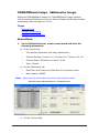
COMMANDbatch Setups - Additional for Integra
Additional COMMANDbatch setups for COMMANDbatch Integra systems
include creating Calibration records for Metered Feeds and Moisture Probes,
and adding a belt warning horn circuit.
Topics
Metered Feeds
Moisture Probe Setup
Moisture Probe Calibration
Metered Feeds
1.
On the Calibrations form, create a new record and enter the
following information:
a) At the top of form:
—
The Interface Parameter that was created earlier
—
Channel Number: Counter 1=1, Counter 2=2, Counter 3=3, etc.
—
Channel Name: Whatever you want it to be
—
Type: Counter
b) On the Calibrations tab:
Note:
—
Grad Size: Must match the Grad Size of the physical meter
—
Max Capacity: 99999
Make sure the units match the units of the physical meter.
Metered Feed Calibration Record - Calibrations tab
c) On the Counters tab:
12
10/19/15
—
Meter Input (the Input IO point where the physical meter input is
terminated in the J-Box)
Metered Feed Calibration Record - Counters tab
2.
Select the counter calibration created above in the Meter Source
field of the Metered Feeds form.
Moisture Probe Setup
3.
On the Calibrations form, create a new record and enter the
following information:
a) At the top of form:
—
The Interface Parameter that was created earlier
—
Channel Number: Use the next available number after the Counters.
—
Channel Name: Whatever you want it to be
—
Type: Probe
b) On the Calibrations tab:
—
10/19/15
Grad Size: 0.010
13
—
Max Capacity: 20.00
—
Unit: %
—
Slope: 0.064
—
Y-Intercept: 0.000
Moisture Probe Calibration Record - Calibrations tab
c) On the Registers tab:
—
Physical IO Low (IO point for the probe)
Moisture Probe Calibration Record - Registers tab
4.
14
Select the probe calibration created above in the Probe field of
the Bins/Silos form.
10/19/15
Moisture Probe Calibration
After bake-out is complete, probe calibration is accomplished by modifying the
Y-Intercept value for the probe on the Calibrations form.
Note:
The starting slope for Hydronix moisture probes connected to
Allen-Bradley hardware should be 0.062.
Example:
Say the probe is reading 5.00% on the SMS.
You perform a bake-out and determine that the moisture reading should be
4.00%.
You would then:
1.
Open the Calibrations form and select the probe’s calibration
record.
2.
Click the "Calibrate" button located in the upper right portion of
the form.
3.
Select YES when the calibration warning message appears.
4.
Subtract 1.00% from the "Y-Intercept" value and save your
changes.
The moisture reading on the SMS should now be 4.00%.
10/19/15
15
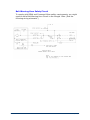
Belt Warning Horn Safety Circuit
To comply with OSHA and Command Alkon safety requirements, you might
need to add a Belt Warning Horn Circuit to the Integra J-Box. (See the
following wiring schematic.)
16
10/19/15
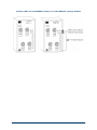
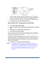
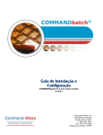
Phoenix EtherNet/IP Bus Coupler
Newer PWS systems use the Phoenix EtherNet/IP Bus Coupler (top of
following photo), which connects to a black Power module and Output and
Input modules under that.
The Phoenix EtherNet/IP Bus Coupler requires separate IP Address
configuration which is normally done at the Command Alkon factory. If you
purchase the “EtherNet/IPTM Made Easy” software to do this yourself, refer to
the “Phoenix EtherNet/IP Bus Coupler - IP Setup” section of this manual.
Phoenix EtherNet/IP Bus Coupler
Phoenix EtherNet/IP Bus Coupler Indicator LEDs
10/19/15
17
During normal operation of the EtherNet/IP Bus Coupler:
•
The Green LEDs in the PWR area will be illuminated as follows:
BO LED off
RY LED on
UL LED on
MS LED on
US LED on
NS LED on
UM LED on
S1 LED off
•
The Output LEDs on the EtherNet/IP Bus Coupler do not indicate polling
by the RTC. If the RTC stops polling the EtherNet/IP Bus Coupler, the RY
and NS LEDs will flash Green.
•
Above the Ethernet Connector, the LNK GREEN indicator should be
illuminated and the YELLOW ACT indicator should be blinking.
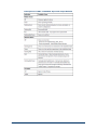
Descriptions of EtherNet/IP Bus Coupler Indicator LEDs
LED
Color
Meaning
State and Description
LNK1
Green
Link at port 1
ON - Link connection at port 1 present
OFF - Link connection at port 1 not present
LNK2
Green
Link at port 2
ON - Link connection at port 2 present
OFF - Link connection at port 2 not present
ACT1
Yellow
Activity on port 1 ON - Data transmission on port 1 active
OFF - Data transmission on port 1 not active
ACT2
Yellow
Activity on port 2 ON - Data transmission on port 2 active
OFF - Data transmission on port 2 not active
BO
Green
Boot
ON - Boot loader active, firmware started
Flashing - Waiting for BootP/DHCP reply
OFF - Firmware started successfully
UL
Green
ULogic
ON - 24 V communications supply / 7.5
communications power present
OFF - 24 V communications supply / 7.5
communications power not present
US
Green
USegment
ON - 24 V segment circuit supply present
OFF - 24 V segment circuit supply not present
UM
Green
UMain
ON - 24 V I/O supply present
OFF - 24 V I/O supply not present
RY
Green
Ready
ON - Connection to a process data client
established
Flashing - Firmware ready to operate
OFF - Firmware not active
ETH
PWR
18
10/19/15
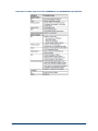
LED
Color
Meaning
State and Description
MS
Red/Green Module status
Green ON - Normal operation
Red ON - Unrecoverable error
Flashing Green:
-- Device not configured, or device
configuration not complete or faulty
-- Device in standby mode
Flashing Red - Recoverable error
Flashing Red/Green - Self-test
OFF - No supply voltage
NS
Green/Red Network status
Green ON - Module is online and has established
a connection
Red ON - Error preventing communication with
the network (e.g., bus offline or double MAC ID)
Flashing Green:
-- Device online, connections not established
-- Device has finished the "double MAC ID" test
but has not established connections to other
nodes
Flashing Red - One or more connections in
timeout state
Flashing Red/Green - Self-test
OFF:
-- Device not online
-- Device has not yet finished the "double MAC
ID" test
-- Device has no IP address or is not supplied
with voltage
S1
Green
Boot source
status
ON - IP parameters received from BootP/DHCP
server
Flashing - BootP request/responses in process
OFF - Stored IP parameters are used
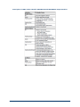
D
Green
Diagnostics
ON - Data transmission within the station active
Flashing - Data transmission within the station
not active
E
Red
Error
ON - Short circuit/overload of outputs
OFF - No short circuit/overload of outputs
1-4
Yellow
O1...O4
ON - Outputs active
OFF - Outputs not active
Yellow
I1...I8
ON - Inputs active
OFF - Inputs not active
O1
I1, I2
1-8
10/19/15
19
Phoenix EtherNet/IP Bus Coupler - IP Setup
Assumption:
The following procedure assumes that the bus coupler and IO
modules are mounted, that the network and power cables are
connected, and that the unit is communicating with COMMANDbatch.
20
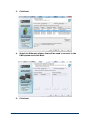
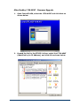
1.
Open the “EtherNet/IP Made Easy” application.
2.
In Windows 7, you will have to “Allow access”.
10/19/15
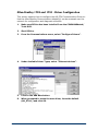
3.
Click Next.
4.
Select the Ethernet adaptor that will be used to connect to the
PWS system and click Next.
5.
Click Next.
10/19/15
21
22
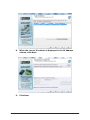
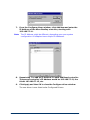
6.
Select the correct device and enter the correct IP address
(192.168.77.11), click Add, and then click Next.
7.
Select the correct device and click "Start Serving IP Address(es)".
10/19/15
8.
When the correct IP address is displayed in the IP Address
column, click Next.
9.
Click Next.
10/19/15
23
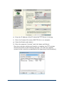
10. Select the correct device from the list and click Next.
11. Uncheck "Enable BootP", click "Write Config", and then click
Next.
24
10/19/15
12. Click Next.
13. Click Exit.
10/19/15
25
Phoenix EtherNet/IP Bus Coupler - Firmware Upgrade
1.
Determine the current firmware version:
a) In an Internet browser address bar, enter the IP Address of the
controller (example: http://192.168.30.10).
The following window is displayed.
b) Click on “Device Information” on the left side of the window.
The current firmware version is displayed (Version 1.10 in this example).
26
10/19/15
2.
Find the latest firmware for the controller:
a) In a browser that is connected to the Internet, enter the following URL
to go to the Phoenix Contact Download Center:
—
10/19/15
http://select.phoenixcontact.com/phoenix/dwl/dwlfr1.jsp?lang=en
27
b) Enter the controller's Order Number (2897758) in the search box in
the middle of the download window and click Search.
A window should be displayed showing available documentation and the
latest firmware file (under the Software section).
28
10/19/15
c) Click on the light blue .zip file link (shown next) to download the file.
Note:
In our example, we already have the latest firmware version (1.10)
so no action would be necessary. But for illustration purposes we
will continue as if we needed to download the file.
d) when asked to Accept the Terms and Conditions, click Accept.
e) Download the .zip file to a location you can find later. When the
download is finished, close the Download and Search Results windows.
10/19/15
29
f)
3.
Locate the .zip file and uncompress and extract the c2897758.fw file to
a location you can find later.
Update the firmware:
Requirement
A TFTP Server must be available on the PC where the Phoenix controller
is connected and in the same IP Address domain.
In our example, we used the jounin.net TFTP Server because it was both
32 and 64 bit compatible with Windows 7. The URL for this application is
http://tftpd32.jounin.net/. Download and install either the 32 or 64 bit
Standard Edition Installer package.
a) From the Start menu, double click on the TFTP Sever icon.
The following window is displayed.
b) Using the Browse button, locate the firmware file (c2897758.fw).
c) In the Server interface field, set the IP Address of the PC.
d) Go back to the Phoenix IL EIP BK web interface screen, click on
“Device Configuration” at the left and then click on “Software Update”
that appears underneath.
The following window should be displayed.
30
10/19/15
e) Enter the IP Address of the PC where the TFTP Server is running.
f)
Enter the firmware file name (c2897758.fw in our example).
g) Select the Enable radio button.
h) Enter the password ("private") and click Apply and Reboot.
Once the controller reboots and transfer is complete, the TFTP window
should look similar to the following example. (To verify the upgrade,
connect to the controller as explained at the beginning of this procedure.)
10/19/15
31
Pulse Rate and Duty Cycle - Phoenix EtherNet/IP Bus Coupler
Model Number
32
Phoenix Contact IL EIP BK DI8 DO4 2TX-PAC
Input Voltages
24vDC
110vAC, 220vAC, 50/60 HZ
Pulse Rate
25 counts per second
15 counts per second
Duty Cycle
50/50
50/50
10/19/15
Allen-Bradley 1794-AENT
The Allen-Bradley 1794-AENT FLEX I/O EtherNet/IP Communication Adapter
replaces the 1794-ADN DeviceNet Adapter when DeviceNet Integra systems
are converted to COMMANDbatch.
Allen-Bradley 1794-AENT Communication Adapter (left) with 4 IO Modules
Each adapter supports up to 8 IO modules, which can be mounted in any
order. If there is not enough room to mount 8 modules in a row, you can use
the optional extender cable shown below.
Indicator LEDs on the 1794-AENT Adapter
10/19/15
33
Allen-Bradley 1794-AENT - Indicator LEDs for Troubleshooting
34
10/19/15
Allen-Bradley 1794-AENT - Changing the IP Address
Note:
The following procedure only pertains to existing/configured 1794AENTs. If you are configuring a new 1794-AENT, see Allen-Bradley
1738 and 1794 - Initial IP Setup.
1.
Select Start > Programs > Rockwell Software > RSLinxClassic.
2.
From the RSLinx window, select Communications > RSWho
3.
On the left side of the RSWho window, expand the list under
AB_ETH-1, ETHERNET then select the 1794-AENT device.
4.
On the right side of the RSWho window, right click on the 1794AENT icon and select “Module Configuration”.
5.
Select the Port Configuration tab, change the IP Address to
192.168.77.xx (where 192.168.77 identifies the CBControlNet
network and xx identifies the controller), and click OK.
Note:
10/19/15
.
IP Addresses should range from 192.168.77.10 - 192.168.77.19
for Fieldbus Controllers, Phoenix EIP or Flex I/O EIP.
35
Pulse Rate and Duty Cycle Specifications
Model Number
36
Allen-Bradley 1794-AENT
Input Voltages
24vDC
110vAC, 220vAC, 50/60 HZ
Pulse Rate
40 counts per second
15 counts per second
Duty Cycle
50/50
50/50
10/19/15
Allen-Bradley 1738-AENT
The Allen-Bradley 1738 EtherNet/IP Communication Adapter replaces the
DeviceNet Adapter when DeviceNet Integra systems are converted to
COMMANDbatch.
The Allen-Bradley 1738 may also be utilized with COMMANDbatch-OS to
support Serial Valve technology.
Allen-Bradley 1738-AENT Communication Adapter (left) with 2 IO Modules
10/19/15
37
Indicator LEDs on the 1738-AENT Adapter
38
10/19/15
Allen-Bradley 1738-AENT - Indicator LEDs for Troubleshooting
10/19/15
39
Indicator LEDs: A-B 1738-IB8M12 (Input) and 1738-OB8EM12 (Output) Modules
40
10/19/15
Descriptions of LEDs: 1738-AENT Input and Output Modules
10/19/15
41
Parker Hannifin PSSN8M12A Input Module (and Connector Wiring)
Parker Hannifin PSSN8M23A Input Module (and Connector Wiring)
42
10/19/15
Description of LEDs: Parker Hannifin PSSN8M12A and PSSN8M23A Input Modules
10/19/15
43
Parker Hannifin PSST8M12A Output Module (and Connector Wiring)
Parker Hannifin PSST8M23A Output Module (and Connector Wiring)
44
10/19/15
Description of LEDs: Parker Hannifin PSST8M12A and PSST8M23A Output Modules
10/19/15
45
Parker Hannifin PSSTV32A Valve Driver Module
Note:
46
Indicator LEDs for the Parker Hannafin PSSV32A are provided on
the next page.
10/19/15
Indicator LEDs: Parker Hannifin PSSV32A Valve Driver Module
10/19/15
47
Allen-Bradley 1738-AENT - Firmware Upgrade
48
1.
Open ControlFLASH, select the 1738-AENT and click Next as
shown below.
2.
Expand the list for the ETHIP-1 driver, select the 1738-AENT
(identified by its IP Address), and click OK as shown below.
10/19/15
3.
Select 3.7.11 from the revision list and click Next as shown below.
4.
When the following window appears, click Finish.
5.
When prompted to begin the update, click Yes.
DO NOT POWER OFF THE UNIT DURING THE FLASH PROCESS!
6.
10/19/15
When the Update Status shows “Update complete.”, click OK.
49
50
10/19/15
Allen-Bradley 1738 and 1794 - Initial IP Setup
This section pertains to the initial setup of new 1738 and 1794-AENTs only.
For existing 1738 and 1794-AENTs, see Allen-Bradley 1738 and 1794 - Driver
Configuration.
Assumption:
The following procedure assumes that the adapter and IO modules
are mounted and that the network and power cables are connected.
To initially set the IP Address on 1738 or 1794-AENTs:
1.
Write down the MAC Address (located on the side of the adapter).
2.
Open the BOOTP/DHCP Server.
A window similar to the following is displayed.
3.
Leave Subnet Mask set to 255.255.255.0 and click OK.
The BOOTP/DHCP window is displayed.
10/19/15
51
4.
Select the 1794-AENT Controller from the list and click the “Add
to Relation List” button.
The following window is displayed.
5.
Note:
6.
52
Enter 192.168.77.11 as the IP Address and click OK.
IP Addresses should range from 192.168.77.10 - 192.168.77.19
for Fieldbus Controllers, Phoenix EIP or Flex I/O EIP.
Select the controller in the Relation List as shown next and click
the “Disable BOOTP/DHCP” button.
10/19/15
7.
Exit the BOOTP/DHCP server.
For 1738-AENT’s Only, do the following:
8.
10/19/15
Open Internet Explorer and connect to http://192.168.77.xx
(where xx is the last octet of the 1738’s IP Address). This opens
the Allen-Bradley 1738 web server.
53
9.
On the menu at the left of the web server window, select
Configuration > Identity then login with “admin” as the user and
“password” as the password.
10. On the Configuration window, enter the Chassis Size (controller
plus number of IO modules) and click “Apply Changes”.
11. Cycle power on the 1738 unit. The Indicator LEDs should now be
green.
54
10/19/15
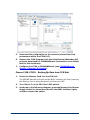
Allen-Bradley 1738 and 1794 - Driver Configuration
This section explains how to configure the AB_ETH Communication Driver so
that the Allen-Bradley Communication Adapter(s) can be accessed over the
network for configuration and diagnostic activities.
1.
Make sure RSLinx has been installed from the COMMANDbatch/
Tools DVD.
2.
Start RSLinx.
3.
From the Communications menu, select “Configure Drivers”.
4.
Under Available Driver Types, select “Ethernet devices”.
5.
Click on the Add New button.
6.
When prompted to name the new driver, leave the default
(AB_ETH-1) and click OK.
10/19/15
55
7.
Note:
From the Configure driver window, click Add New and enter the
IP Address of the Allen-Bradley controller, starting with
192.168.77.11.
The IP Address might be different, depending upon your system
configuration. All adapters have unique IP Addresses.
8.
Repeat step 7 to add an IP Address for each additional controller.
The second controller’s IP Address would be 192.168.77.12, the
third’s 192.168.77.13, etc.
9.
Click Apply and then OK to close the Configure driver window.
The new driver is now listed under Configured Drivers.
56
10/19/15
10. Close RSLinx.
10/19/15
57
Omron CJ2M-CPU31
This section describes the setups needed to make the Omron CJ2M-CPU31
PLC controller work with COMMANDbatch-OS (Open Solution).
As indicated by the following graphic, the CJ2M-CPU31 has a built-in
EtherNet/IP port, a general-purpose network connection for interfacing to
Support Software, Tag Access which can be utilized by COMMANDbatch-OS,
and several additional Serial communications ports.
Omron CJ2M-CPU31 PLC Controller
58
10/19/15
CJ2M - Setting the IP Address
1.
If the current IP is known, connect CX-Programmer via the
EtherNet Cable. If the current IP is unknown, connect CXProgrammer via a USB Cable.
2.
Using CX-Programmer, set the IP address in Unit Settings.
3.
Transfer Settings (PC to Unit).
4.
Set the CJ2M Unit No. switch to Zero.
5.
Set the CJ2M Node No. switches to the last octet of the IP address
(in hexadecimal).
6.
Power cycle the CJ2M and watch for the correct IP and Node
display on the LED.
7.
Test the EtherNet connection via Ping and CX-Programmer.
CJ2M - Validate Hardware Configuration
Using CX-Programmer, validate that the PLC IO Table matches the actual
hardware configuration.
Sample Only - Your layout will depend on your system’s configuration.
10/19/15
59
CJ2M - Configure DataLink Tag Set
1.
Connect to the Network.
2.
Using Network Configurator, configure the Data Link Tag Set and
contents.
3.
On the In-Consume tab for Output Points (2 bytes per DO
Module), set the Advanced Instance Number to 101.
4.
On the Out-Produce tab for Input points DI, AI, and Scale
mappings, set the Advanced Instance Number to 100.
Note:
60
Each DI Module requires 2 bytes and each AI Module requires 20
bytes. Scale mapping (DeviceNet Adapter) requires 64 Words (128
bytes), one word for each sub-node connected to the Adapter.
10/19/15
5.
Download the configuration to the network (stores Data Link
parameters within the CJ2M PLC).
6.
Replace the CJ2M Program with the Initialization/Watchdog PLC
program developed for COMMANDbatch (instructions to be added
later to this document).
7.
Configure the CJ2M in COMMANDbatch (see COMMANDbatch
Setups - EtherNet/IP Devices).
Omron CJ2M-CPU31 - Backing Up Data from CPU Unit
1.
Insert the Memory Card into the CPU Unit.
The MCPWR indicator will light and the BUSY indicator will flash (meaning
the Memory Card is being accessed) and then turn OFF.
2.
Turn ON pin 7 on the CPU Unit's DIP switch.
3.
As shown in the following diagram, press the Memory Card Power
Supply Switch for three seconds until the BUSY indicator lights,
and then release the switch.
10/19/15
61
The PLC will start backing up data to the Memory Card. The MCPWR
indicator will flash once and then light while the data is being written. At
the same time the BUSY indicator will flash. The MCPWR and BUSY
indicators will both turn OFF when the operation is completed normally.
4.
Turn OFF pin 7 on the CPU Unit's DIP switch.
Omron CJ2M-CPU31 - Restoring Data from CPU Unit
1.
Turn OFF the PLC power supply.
2.
Insert the Memory Card containing the backup files into the CPU
Unit.
3.
Turn ON pin 7 on the CPU Unit's DIP switch.
4.
Turn ON the PLC power supply.
The PLC will start restoring the data from the Memory Card. The MCPWR
indicator will flash once and then light while the data is being read. At the
same time the BUSY indicator will flash.
The MCPWR and BUSY indicators will both turn OFF when the operation is
completed normally. If the MCPWR indicator flashes five times, or if only the
BUSY signal turns OFF, it means that an error has occurred. (Refer to the
“Verifying Backup Operations with Indicators” section of the CJ2 CPU Unit
Hardware User’s Manual.)
5.
Turn OFF pin 7 on the CPU Unit's DIP switch.
Notes: •
•
62
The backup function will override the automatic transfer at
startup function, so the backup files will be read to the CPU Unit
when the PLC is turned ON even if pin 2 of the DIP switch is ON.
Data will not be read from the Memory Card to the CPU Unit if
pin 1 of the DIP switch is ON (write-protecting program
memory).
10/19/15
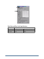
Pulse Rate and Duty Cycle - Omron CJ2M-CPU31
Model Number
Omron CJ2M-CPU31
Input Voltages
24vDC
110vAC, 220vAC, 50/60 HZ
Pulse Rate
20 counts per second
15 counts per second
Duty Cycle
50/50
50/50
10/19/15
63
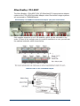
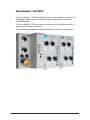
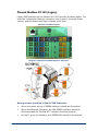
Phoenix Modbus ILC150 (Legacy)
Legacy PWS systems use the Phoenix ILC150 Controller as shown below. The
controller includes the Ethernet connector (top of photo), the black Power
module, and the Output and Input modules under that.
Phoenix ILC150 Controller
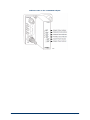
Diagram of Phoenix ILC150 Diagnostic Indicators
During normal operation of the ILC150 Controller:
64
•
Above the power wiring, 4 GREEN indicators should be illuminated.
•
Above the Ethernet Connector, the LNK GREEN indicator should be
illuminated and the YELLOW ACT indicator should be blinking.
•
On the I1 group of indicators, the GREEN RDY should be illuminated.
10/19/15
•
If COMMANDbatch is communicating with the MIC, the YELLOW Q1
indicator should be blinking. If no communications are taking place, the
YELLOW Q2 indicator will be steadily illuminated.
Descriptions of the ILC150 Indicator LEDs.
Label
Color
Meaning
Green
Connection established.
On
Able to contact another device.
Yellow
Transmission activity.
On
Transmitting or Receiving.
Green
Controller Run Status.
Off
Controller Runtime stopped.
Flashing
Runtime system initialized.
On steady
Runtime in Run state.
Yellow
Failure.
On
Runtime program error.
Off
Runtime program OK.
ETH
LNK1
ACT
PLC/POWER
FR
FF
INTERBUS Diagnostics - Top of I1 and I2
RDY
FAIL
BSA
PF
Green
INTERBUS Status.
Flashing
INTERBUS Active and Ready.
On
INTERBUS Running.
Red
Failure.
On
Bus or Controller Error.
Yellow
Bus Segment Aborted.
On
One or more Bus Segments are switched off.
Yellow
Peripheral Fault.
On
Peripheral fault on one of the Modules.
O1 - Integrated Output
Q1
Q2
Q3
10/19/15
Yellow
Output On/Off Status.
Blinking
Used by the internal Controller program to
indicate that the COMMANDbatch RTC is
polling for data.
Yellow
Output On/Off Status.
On
Used by the internal Controller program to
indicate that polling is not functioning and all
other Outputs have been turned Off for safety.
Yellow
Output On/Off Status.
On
Not utilized by PWS.
65
Label
Color
Meaning
Q4
Yellow
Output On/Off Status.
On
Not defined yet.
I1 and I2 - Integrated Digital Inputs
I1 thru I8
Yellow
Input On/Off Status.
On
Not utilized by PWS.
PWR - Controller Input Power Status
UL
US
UM
Green
24V supply UILC for generating the voltages
UL and UANA.
On
Supply voltage present (indication if 24V
supply voltage UILC present).
Green
24V supply for segment circuit.
On
Supply voltage present.
Green
24V supply for main circuit.
On
Supply voltage present.
Note: Under normal conditions, all Power (UL, US, and UM), Controller
Run (FR), and INTERBUS Active and Ready (RDY) indicators
should be ON steady and the Q1 indicator should be blinking
while the Precision Water System software is functioning.
66
10/19/15
Phoenix Modbus ILC150 (Legacy) - IP Setup
Assumption:
The following procedure assumes that the controller and IO modules
are mounted, that the network and power cables are connected, and
that the unit is communicating with COMMANDbatch.
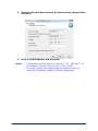
1.
Open the IP Assignment Tool.
2.
Click Next.
10/19/15
67
3.
Select the Phoenix device whose IP address needs changed then
click Next.
4.
Enter a valid IP address and click Next.
Notes:
•
•
68
IP Addresses should range from 192.168.77.10 - 192.168.77.19
for Fieldbus Controllers, Phoenix EIP or Flex I/O EIP.
If several minutes have elapsed and the application has not
saved the IP Address, restart the Phoenix equipment.
10/19/15
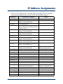
IP Address Assignments
Here is a list IP Addresses to be used when you assign them to external
components/hardware that connect to the CBControlNet network.
IP Address
Component / Adaptor
Notes
192.168.77.1
Managed Switch (Gateway and DNS) For virtual networks
192.168.77.2
RTC Ethernet NIC
(Plant 1 Control Network)
192.168.77.2
vRTC Ethernet NIC
192.168.77.3
Main COMMANDbatch PC or Host PC
(second Ethernet connection named
“CBControlNet”)
192.168.77.4
RTC Ethernet NIC
(Plant 2 Control Network)
192.168.77.5
RTC Ethernet NIC
(Plant 3Control Network)
192.168.77.6
192.168.77.7
USB Ethernet Adapter for diagnostics
(Plant 3 Control Network)
192.168.77.8
USB Ethernet Adapter for diagnostics
(Plant 2 Control Network)
192.168.77.9
USB Ethernet Adapter for diagnostics
(Plant 1 Control Network)
192.168.77.10
Open Solution Hardware with Admix
Extension, PWS, PTS, Etc.
Use next available IP
address in range 10-19.
Open Solution Hardware with
EtherNet/IP Scale Indicator
Use next available IP
address in range 20-29.
192.168.77.11
192.168.77.12
192.168.77.13
192.168.77.14
192.168.77.15
192.168.77.16
192.168.77.17
192.168.77.18
192.168.77.19
192.168.77.20
192.168.77.21
192.168.77.22
192.168.77.23
192.168.77.24
192.168.77.25
10/19/15
69
IP Address
Component / Adaptor
Notes
192.168.77.26
192.168.77.27
192.168.77.28
192.168.77.29
192.168.77.150 VM Fiber Feeders 1
(Plant 1 Control Network)
192.168.77.151 VM Fiber Feeders 2
(Plant 2 Control Network)
192.168.77.152
192.168.77.199
Reserved
192.168.77.200 E-Z CAL IP Manual Station 1
(Plant 1 Control Network)
Use next availabe IP address
in range 200-209.
192.168.77.201 E-Z CAL IP Manual Station 2
(Plant 1 Control Network)
192.168.77.202
192.168.77.203
192.168.77.204 E-Z CAL IP Manual Station
(Plant 2 Control Network)
192.168.77.205
192.168.77.206
192.168.77.207
192.168.77.208
192.168.77.209
192.168.77.210 E-Z CAL IP J-Box 1
(Plant 1 Control Network)
Use next availabe IP address
in range 210-219.
192.168.77.211 E-Z CAL IP J-Box 2
(Plant 1 Control Network)
192.168.77.212
192.168.77.213
192.168.77.214 E-Z CAL IP J-Box
(Plant 2 Control Network)
192.168.77.215
192.168.77.216
192.168.77.217
192.168.77.218
192.168.77.219
70
192.168.78.2
vRTC Control Network
192.168.78.3
TenAsys Virtual Adapter
10/19/15