1
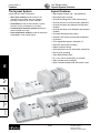
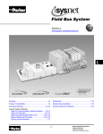
(Revised 11-25-2009) Isysnet Fieldbus System Section E www.parker.com/pneu/Isysnet Isys ISO Isys Micro E Features....................................................................E144 Dimensions...................................................... E164-E166 Fieldbus Modules............................................ E145-E147 Related Documentation.............................................E167 Using Bus Extender Cables............................ E148-E149 Technical Service Programs......................................E168 E143 Valvair II Isysnet System Selection Select a Communication Interface Module... E150-E151 Select I/O Modules........................................ E152-E156 Select the Appropriate Power Unit................ E156-E160 Select Cables and Cordsets......................... E161-E162 Placing Isysnet Modules.........................................E163 DX Isomax Isysnet TM Parker Hannifin Corporation Pneumatic Division Richland, Michigan www.parker.com/pneumatics Features Isys Series Valves Isysnet System Selection The Isysnet System Isysnet Features Isysnet has four major components: • Highly modular design (4pt – 16pt modularity) • Valve driver module provide control for 32 solenoids on a manifold, with bus extension providing connectivity to 3 more manifolds • Broad application coverage Catalog 0600P-11 • I/O modules provide the field interface, systeminterface circuitry, and bases for mounting • Communication interface modules provide the network-interface circuitry • Power distribution module provide the solution to expandability of the Isysnet system • Channel-level diagnostics (LED and electronic) • Channel-level alarm and annunciation (electronic) • Channel-level open-wire detection with electronic feedback • Channel-level short-circuit detection with electronic feedback • Parameter-level explicit messaging • Horizontal and vertical mounting without derating • 5g vibration • Flash upgradable adapters and digital I/O • Electronic and mechanical keying • Robust backplane design • Quick-disconnects for I/O and network connectivity • Built-in panel grounding • Color-coded module labels • UL, C-UL, and CE certifications (as marked) • Highly reliable structural integrity • Optical isolation between field and system circuits E Isys Micro Isys ISO Isysnet DX Isomax Valvair II E144 Parker Hannifin Corporation Pneumatic Division Richland, Michigan www.parker.com/pneumatics Catalog 0600P-11 (Revised 11-25-09) Fieldbus Modules Isys Series Valves Isysnet Fieldbus System Communications Module Protocol Part Number DeviceNet™ PSSCDM18PA (7/8" Mini) or PSSCDM12A (M12) ControlNet™ PSSCCNA EtherNet I/P PSSCENA Profibus-DP® PSSCPBA ™ All Modules IP67 Certified Reference the following Documents for Installation Instructions. DeviceNet - E101P, PSS-UM001A; Control Net - E103P Ethernet I/P - E104P; Profibus-DP - E102P EDS and GSD files located at www.parker.com/pneu/Isysnet PSSCENA PSSCCNA Devicebus Terminating Resistor DeviceNet M12 Type A P8BPA00MA Profibus-DP M12 Type B P8BPA00MB P8BPA00MA E Digital Inputs 8 Digital Inputs M12, 5-Pin (NPN Sinking - Requires PNP Sourcing Input Device) PSSN8M12A 10 to 28.8VDC 8 Digital Inputs M12, 5-Pin (PNP Sourcing - Requires NPN Sinking Input Device) PSSP8M12A 10 to 28.8VDC 8 Digital Inputs M8, 3-Pin (NPN Sinking - Requires PNP Sourcing Input Device) PSSN8M8A 10 to 28.8VDC 8 Digital Inputs M8, 3-Pin (PNP Sourcing - Requires NPN Sinking Input Device) PSSP8M8A 10 to 28.8VDC 8 Digital Inputs M23, 12-Pin (PNP Sourcing - Requires NPN Sinking Input Device) PSSP8M23A 10 to 28.8VDC 8 Digital Inputs M23, 12-Pin (NPN Sinking - Requires PNP Sourcing Input Device) PSSN8M23A 10 to 28.8VDC PSSN16M12A Isys ISO 10 to 28.8VDC Isysnet PSSN16M12A Isys Micro Voltage DX Isomax Part Number PSSN8M8A Valvair II I/O Modules 16 Digital Inputs M12, 5-Pin (NPN Sinking - Requires PNP Sourcing Input Device) All Modules IP67 Certified Reference E106P Documents for Installation Instructions. See www.parker.com/pneu/Isysnet PSSP8M23A E145 Parker Hannifin Corporation Pneumatic Division Richland, Michigan www.parker.com/pneumatics (Revised 11-25-09) Catalog 0600P-11 Fieldbus Modules Isys Series Valves Isysnet Fieldbus System Digital Outputs + + + + + § + I/O Modules Part Number Voltage 16 Digital Outputs M23, 19-Pin (PNP Sourcing) PSST16M23A 10 to 28.8VDC 16 Digital Outputs D-Sub, 25-Pin, (PNP Sourcing) PSST16D25A 10 to 28.8VDC 16 Digital Outputs M12, 5-Pin (PNP Sourcing) PSST16M12A 10 to 28.8VDC 8 Digital Outputs M12, 5-Pin (PNP Sourcing) PSST8M12A 10 to 28.8VDC 8 Digital Outputs M8, 3-Pin (PNP Sourcing) PSST8M8A 10 to 28.8VDC 4 Digital Output, High Watt Relay M12, 5-Pin (PNP Sourcing) (2 Amp) PSSTR4M12A 8 Digital Outputs M23, 12-Pin (PNP Sourcing) PSST8M23A PSST16D25A PSST16M12A 24VDC 10 to 28.8VDC All Modules IP67 Certified Reference the following Documents for Installation Instructions. + E107P § E109P See www.parker.com/pneu/Isysnet E PSST8M12A Analog Inputs I/O Modules ‡ ‡ Isys Micro Part Number Voltage 2 Analog Inputs Voltage M12, 5-Pin PSSNAVM12A 0 to 10V ± 10V 2 Analog Inputs Current M12, 5-Pin PSSNACM12A 4 to 20mA or 0 to 20mA All Modules IP67 Certified Reference the following Documents for Installation Instructions. ‡ E110P See www.parker.com/pneu/Isysnet PSSNACM12A Isys ISO Isysnet DX Isomax Analog Outputs I/O Modules ** Valvair II ** Part Number Voltage 2 Analog Outputs Voltage M12, 5-Pin PSSTAVM12A 0 to 10V ± 10V 2 Analog Outputs Current M12, 5-Pin PSSTACM12A 4 to 20mA or 0 to 20mA All Modules IP67 Certified Reference the following Documents for Installation Instructions. **E111P See www.parker.com/pneu/Isysnet PSSTACM12A E146 Parker Hannifin Corporation Pneumatic Division Richland, Michigan www.parker.com/pneumatics Isys Series Valves Isysnet Fieldbus System Catalog 0600P-11 Fieldbus Modules Terminating Base Module Extender Module Termination Base for Stand Alone Units Part Number PSSTERM Used as the last Terminating Module for a Stand Alone Isysnet Assembly. PSSTERM Power Extender Module Extender Module Part Number PSSSE24A 24VDC Field Power Module A Power Extender Module must be used on every 14th Module in an Isysnet assembly. See www.parker.com/pneu/Isysnet Reference Document E105P and PSS-SG001 for configuration instructions. See www.parker.com/pneu/Isysnet PSSSE24A PSSEXT1 24VDC 3 Meter Cable* PSSEXT3 24VDC Isys ISO * Requires a PSSSE24 Power Extender Module IP67 Certified Reference the following Documents for Installation Instructions. E117P See www.parker.com/pneu/Isysnet DX Isomax PSSEXT1 PSSVEXT1 Valvair II Isys Micro Bus Extender Cable 1 Meter Cable* Isysnet 1 Meter Cable* Isys Micro Bus Extender Cable E 24VDC IP67 Certified PSSVEXT1 E147 Parker Hannifin Corporation Pneumatic Division Richland, Michigan www.parker.com/pneumatics Isys Series Valves Isysnet Fieldbus System Catalog 0600P-11 Bus Extender Cables Using Bus Extender Cables Example #1: Isys Micro with Standard Bus Extender Cable • Separate the communication module and a portion of the I/O from other I/O and the valve manifold. • Commonly used when overall length is restricted. • PSSSE24A is needed on the extension. No 24VDC connector needed on the Isysnet end plate. PSSEXT1 Power #2 PSSSE24A Power #1 E Example #2: Isys Micro with Bus Extension on Valve Driver Module – No additional I/O at the Extension • Add up to three additional valve manifolds without adding another communication module. • No PSSSE24A is needed on the Extension when the Valve Driver Module with 24VDC Connector is used. Isys Micro • Commonly used when many valves are required. Isys ISO Valve Driver with Bus Extension Valve Driver with Bus Extension and 24VDC Connector Isysnet Valve Driver with 24VDC Connector DX Isomax Power #1 Valvair II Power #2 PSSVEXT1 Power #3 PSSVEXT1 E148 Parker Hannifin Corporation Pneumatic Division Richland, Michigan www.parker.com/pneumatics Isys Series Valves Isysnet Fieldbus System Catalog 0600P-11 Bus Extender Cables Using Bus Extender Cables Example #3: Isys Micro with Bus Extension on Valve Driver – With I/O at Extension • Add up to three additional valve manifolds without adding another communication module. • PSSSE24A is needed on the Extension. No 24VDC Connector needed on the Isysnet end plate. • Commonly used when many valves are required, and each location requires additional I/O. Valve Driver with Bus Extension Power #1 Power #2 PSSSE24A PSSVEXT1 E Example #4: Isys Micro with Bus Extension on Valve Driver Module – With I/O at the Extension and larger Isys ISO Valve Manifold Isys Micro • Add up to two additional Isys Micro valve manifolds and one Isys ISO valve manifold without adding another communication module. • PSSSE24A is needed on the Extension. Isys ISO • Isys ISO valve manifold must be the last manifold on the Extension Isysnet • Commonly used when many valves are required, and each location requires additional I/O. Power #1 Valvair II DX Isomax Valve Driver with Bus Extension Power #2 PSSSE24A PSSVEXT1 E149 Parker Hannifin Corporation Pneumatic Division Richland, Michigan www.parker.com/pneumatics Isys Series Valves Isysnet System Selection Catalog 0600P-11 Communication Modules Specifying an Isysnet System Follow these steps as you specify your Isysnet system: Step 1 Select a Communication Interface Module Choose the interface module for your operating system. Selecting a Network Selecting the DeviceNet Communication Interface 2 Select I/O Devices Based on Field Devices Location of the device Number of Isysnet modules needed Number of I/O available per module Number of modules Digital I/O Modules Analog I/O Modules Valve Driver Module 3 Select Optional Power Component Choose optional component to extend backplane power Expansion Power Unit Typical Configurations 4 Select Accessories Cables and Cordsets 5 Placing Isysnet Modules Determine necessary dimensions based on the communication interface chosen. Placing Isysnet Modules Mounting the Isysnet System Step 1 Select a Communication Module Selecting Isysnet Communication Interfaces Rockwell Automation NetLinx Architecture E Separate communication interface adapters are available for different networks. Install adapters into the PointBus backplane to allow Isysnet modules to communicate with a controller. Isys Micro NetLinx open network architecture is the Rockwell Automation strategy of using open networking technology for seamless, top-floor to shop-floor integration. The networks in the NetLinx architecture, DeviceNet, ControlNet, and EtherNet/IP, speak a common language and share a universal set of communication services. NetLinx architecture, part of the Integrated Architecture, seamlessly integrates all the components in an automation system from a few devices on one network to multiple devices on multiple networks including access to the Internet, helping you to improve flexibility, reduce installation costs, and increase productivity. Communication Considerations Isys ISO Isysnet features are impacted by your network choice. Network Impact Isysnet DX Isomax Valvair II DeviceNet PSSCDM12A and PSSCDM18PA DeviceNet offers high-speed access to plant-floor data from a broad range of plant-floor devices and a significant reduction in wiring. The PSSCDM12A and PSSCDM18PA provide two means of connecting a node of I/O to DeviceNet. A total of 63 Isysnet modules can be assembled on a single DeviceNet node. ControlNet™ PSSCCNA ControlNet allows intelligent, high-speed control devices to share the information required for supervisory control, work-cell coordination, operator interface, remote device configuration, programming, and troubleshooting. A total of 63 Isysnet modules can be assembled on a single ControlNet node. Up to 25 direct connections and 5 rack connections are allowed. EtherNet/IP™ PSSCENA EtherNet/IP is an open industrial networking standard that supports implicit and explicit messaging and uses commercial, off-the-shelf EtherNet equipment and physical media. A total of 63 Isysnet modules can be assembled on a single EtherNet/IP node. Refer to the User Manual, publication PSS-UM004 to determine the ratings for direct and rack connections allowed. PROFIBUS DP™ PSSCPBA A total of 63 Isysnet modules can be assembled on a single PROFIBUS node. E150 Parker Hannifin Corporation Pneumatic Division Richland, Michigan www.parker.com/pneumatics Isys Series Valves Isysnet System Selection Catalog 0600P-11 Communication Modules Selecting a Network You can configure your system for information exchange between a range of devices and computing platforms and operating systems. Application Requirements Network Select EtherNet/IP PSSCENA ControlNet PSSCCNA • Plant management (material handling) • Configuration, data collection, and control on a single, high-speed network • Time-critical applications with no established schedule • Data sent regularly • Internet/Intranet connection • High-speed transfer of time-critical data between controllers and I/O devices • Deterministic and repeatable data delivery • Media redundancy • Controller redundancy • Intrinsic safety • Redundant controller systems • Connections of low-level devices directly to plant-floor controllers, without interfacing them • Data sent as needed DeviceNet • More diagnostics for improved data collection and fault detection PSSCDM12A PSSCDM18PA • Less wiring and reduced start-up time than a traditional, hard-wired system • Connecting to an existing PROFIBUS DP 5m bus,12 MB network PROFIBUS PSSCPBA E Selecting the DeviceNet Communication Interface Isysnet offers two interfaces for connecting to DeviceNet. Refer to the following table. Remember Select All Isysnet modules count as a single node on the Main Network. PSSCDM12A (M12-style network connectors). Allows a group of I/O modules on the Subnet to act as a single node on the Main Network. The Main Network distance is acceptable. PSSCDM18PA (mini-style network connectors with pass-through). RSNetWorx™ for DeviceNet software is needed for configuration of the PSSCDM12A or PSSCDM18PA on the Main Network and the PointBus Configuration on the PointBus consists of a scan list that is very similar to those used in all of the DeviceNet master scanner modules. Isysnet expansion power supplies are permitted to add more Isysnet modules. • 250 bytes (248 data + 2 bytes status info) for polled input data Isysnet • 250 bytes (248 data + 2 bytes status info) for COS/ cyclic input data • 8 bytes (6 data + 2 status info) for strobe input data E151 Parker Hannifin Corporation Pneumatic Division Richland, Michigan www.parker.com/pneumatics DX Isomax The data coming through the PSS adapter combined with the other data from the Main Network cannot exceed the data capability of the Main Network master scanner. If this occurs, you will need multiple master scanners on the Main Network and the I/O modules on the Subnet will need to be split between multiple PSSCDM12A or PSSCDM18PA adapters. Valvair II It is important that the total amount of data coming from the Subnet does not exceed the data capability of either the PSSCDM12A or PSSCDM18PA. • 250 bytes (248 data + 2 bytes command info) for output data (used as either COS, cyclic, or poll) Isys ISO Behaves as a slave device on the Main Network and a master on the PointBus. Isys Micro For These Features Isys Series Valves Isysnet System Selection Catalog 0600P-11 Digital I/O Modules Step 2 Select I/O Modules Selecting Isysnet Modules Some modules have diagnostic features, electronic fusing, or individually isolated inputs/outputs. The Isysnet family provides a wide range of input and output modules to span many applications, from highspeed discrete to process control. Isysnet supports producer/consumer technology, which allows input information and output status to be shared among multiple Logix controllers. The Isysnet family of I/O modules includes: •Digital I/O Modules •Analog I/O Modules •Valve Driver Module Isys ISO PSST8M8A 24V dc Out PSSCDM12A E PSSN8M12A 24V dc In 0 2 1 3 PSST8M12A 24V dc Out 0 2 1 3 PSSV32A DeviceNet Out Adapter Status DeviceNet In 0 6 2 8 6 4 x10 MOD 1 4 2 3 0 1 1 1 2 4 Isys Micro 6 7 5 4 6 5 7 3 4 5 7 Fault 2 3 6 4 5 PWR Net 0 4 5 Mod NET 0 3 4 MOD NET 2 Adapter Power x1 MOD NET System Power 0 2 8 0 DeviceNet Status PointBus Status 5 6 6 6 7 7 7 Isys ISO Isys Micro Isysnet PSST8M8A 24V dc Out PSSCDM12A PSSN8M12A 24V dc In MOD NET PSST8M12A 24V dc Out FAULT 0 2 1 3 0 2 1 3 POWER DeviceNet Out DX Isomax Adapter Status DeviceNet In 0 0 2 8 Valvair II 6 x10 4 0 1 DeviceNet Status PointBus Status 2 8 6 4 x1 System Power MOD 2 3 Adapter Power 5 7 NET 0 0 0 1 1 1 2 2 4 6 4 5 6 MOD NET 3 4 PWR MOD NET 3 2 4 6 5 7 4 5 7 5 3 4 5 6 6 6 7 7 7 E152 Parker Hannifin Corporation Pneumatic Division Richland, Michigan www.parker.com/pneumatics Analog I/O Modules Isys Series Valves Isysnet System Selection Digital I/O Modules Digital DC Input Modules Catalog 0600P-11 PSSN8M8A PSSP8M8A PSSN8M12A PSSN16M12A PSSP8M12A PSSN8M23A PSSP8M23A Choose digital I/O modules when you need: • Input Modules. An input module responds to an input signal in the following manner: Number of Inputs 8 Sinking Keyswitch Position 1 1 Voltage, On-State Input, Nom. 24VDC 24VDC Voltage, On-State Input, Min. 10VDC 10VDC - Logic circuits process the signal. Voltage, On-State Input, Max. 28.8VDC 28.8VDC - An input LED turns on or off indicating the status of the corresponding input device. Input Delay Time, ON to OFF 0.5 ms hardware + (0…65 ms selectable)* • Output Modules. An output module controls the output signal in the following manner: 0.5 ms hardware + (0…65 ms selectable)* Current, On-State Input, Min. 2 mA 2 mA - Logic circuits determine the output status. Current, On-State Input, Max. 5 mA 5 mA Current, Off-State Input, Max. 1.5 mA 1.5 mA - Optical isolation separates module logic and bus circuits from field power. PointBus Current (mA) 75 75 - The output driver turns the corresponding output on or off. Power Dissipation, Max. 1.0 W @ 28.8VDC 1.0 W @ 28.8VDC Input filtering limits the effect of voltage transients caused by contact bounce and/or electrical noise. If not filtered, voltage transients could produce false data. All input modules use input filtering. - Optical isolation shields logic circuits from possible damage due to electrical transients. - An output LED indicates the status of the output signal. 16 Sinking 8 Sourcing * Input ON-to-OFF delay time is the time from a valid input signal to recognition by the module. • Surge Suppression. Most output modules have built-in surge suppression to reduce the effects of high-voltage transients. However, we recommend that you use an additional suppression device if an output is being used to control inductive devices, such as: E - Motors Additional suppression is especially important if your inductive device is in series with, or parallel to, hard contacts such as: Number of Outputs 8 sourcing 16 Sourcing Keyswitch Position 1 Voltage, On-State Output, Nom. - Push buttons 24VDC - Selector switches Voltage, On-State Output, Min. 10VDC The digital I/O modules support: • A wide variety of voltage interface capabilities Voltage, On-State Output, Max. 28.8VDC • Isolated and non-isolated module types Output Current Rating, Max. • Point-level output fault states 3.0 A per module, 1.0 A per channel • Choice of direct-connect or rack-optimized communications PointBus Current (mA) 75 Power Dissipation, Max. 1.2 W @ 28.8VDC • Field-side diagnostics on select modules Connector types are indicated by the catalog number. For example, the PSSN8M12A has an M12 connector. E153 Parker Hannifin Corporation Pneumatic Division Richland, Michigan www.parker.com/pneumatics Isys ISO PSST16M223A PSST16D25A PSST16M12A Isysnet PSST8M8A PSST8M12A PSST8M23A - Solenoids DX Isomax - Motor starters Isys Micro Digital DC Output Modules - Relays Valvair II - Isys Series Valves Isysnet System Selection (Revised 11-25-09) Catalog 0600P-11 Analog I/O Modules • Ability to direct output device operation during an abnormal condition. Each channel of the output module can be individually configured to hold its last value or assume a user-defined value on a fault condition. This feature allows you to set the condition of your analog devices, and therefore your control process, which may help to ensure a reliable shutdown. Relay Output Module PSSTR4M12A Number of Outputs 4 Form A (N.O.) relays, isolated Keyswitch Position 7 Output Delay Time, ON to OFF, Max. 26 ms* Contact Resistance, Initial 30 mΩ Current Leakage, Off-State Output, Max. 1.2 mA and bleed resistor thru snubber circuit @ 240V ac Output Current Rating, Max 8.0 A per module, 2.0 A per channel PointBus Current (mA) 90 Power Dissipation, Max. 0.5 W • Ability to individually enable and disable channels. Disabling unused channels improves module performance. • Selectable input filters This lets you select the filter frequencies for each channel that best meets the performance needs of your application based on environmental limitations. Lower filter settings provide greater noise rejection and resolution. Higher filter settings provide faster performance. Note: The analog modules provide four input filter selections. *Time from valid output off signal to relay deenergization by module. • Selectable response to broken input sensor. This feature provides feedback to the controller that a field device is not connected or operating properly. This lets you specify corrective action based on the bit or channel condition. Analog I/O Modules E • High accuracy. The modules share a high accuracy rating of ±0.1% of full-scale accuracy at 25 °C. The Isysnet analog modules support: on-board, channel-level data alarming (four set-points per channel); scaling to engineering units; channel-level diagnostics (electronic bits and LEDs); and integer format. Choose analog I/O modules when you need: • Individually configurable channels to use the module(s) with a variety of sensors. Isys Micro Isys ISO • On-board scaling to eliminate the need to scale the data in the controller. Controller processing time and power are preserved for more important tasks, such as I/O control, communications, or other user-driven functions. Isysnet DX Isomax • On-line configuration. Modules can be configured in the RUN mode using the programming software or the control program. This allows you to change configuration while the system is operating. For example, the input filter for a particular channel could be changed, or a channel could be disabled based on a batch condition. To use this feature, the controller and network interface must also support this feature. Valvair II • Over- and under-range detections and indications. This eliminates the need to test values in the control program, saving valuable processing power of the controller. In addition, since alarms are handled by the module, the response is faster and only a single bit per channel is monitored to determine if an error condition has occurred. E154 Parker Hannifin Corporation Pneumatic Division Richland, Michigan www.parker.com/pneumatics Isys Series Valves Isysnet System Selection Catalog 0600P-11 Specifications Analog Input Modules PSSNACM12A PSSNAVM12A Number of Inputs 2 2 Keyswitch Position 3 3 Input Signal Range 4…20 mA 0…20 mA 0…10V ±10V Input Resolution, Bits 16 bits - over 21 mA 0.32 µA/cnt 15 bits plus sign 320 µV/cnt inunipolar or bipolar mode Absolute Accuracy, Current Input 0.1% Full Scale @ 25°C*† — Absolute Accuracy, Voltage Input — 0.1% Full Scale @ 25°C*† Input Step Response, per Channel 70 ms @ Notch = 60 Hz (default) 80 ms @ Notch = 50 Hz 16 ms @ Notch = 250 Hz 8 ms @ Notch = 500 Hz 70 ms @ Notch = 60 Hz (default) 80 ms @ Notch = 50 Hz 16 ms @ Notch = 250 Hz 8 ms @ Notch = 500 Hz Input Conversion Type Delta Sigma Delta Sigma PointBus Current (mA) 75 75 Power Dissipation, Max. 0.6 W @ 28.8VDC 0.6 W @ 28.8VDC * Includes offet, gain, non-linearity and repeatability error terms. † Analog input modules support these configurable parameters and diagnostics: open-wire with LED and electronic reporting; four-alarm and annunciation set-points; calibration mode and electronic reporting; under- and over-range and electronic reporting; channel signal range and update rate and on-board scaling; filter-type; channel update rate. E PSSTAVM12A Number of Outputs 2 2 Keyswitch Position 4 4 Output Signal Range 4…20 mA 0…20 mA Output Resolution, Bits 13 bits - over 21 mA 2.5 µA/cnt 14 bits (13 plus sign) 1.28 mV/cnt inunipolar or bipolar mode Absolute Accuracy, Current Output 0.1% Full Scale @ 25°C*† — Absolute Accuracy, Voltage Output — 0.1% Full Scale @ 25°C*† Step Response to 63% of FS, 24 µs — Current Output Step Response to 63% of FS, — 20 µs Voltage Output Output Conversion Rate 16 µs 20 µs PointBus Current (mA) 75 75 Power Dissipation, Max. 1.0 W @ 28.8VDC 1.0 W @ 28.8VDC * Includes offet, gain, non-linearity and repeatability error terms. † Analog output modules support these configurable parameters and diagnostics: open-wire with LED and electronic reporting (PSSTACM12A only); fault mode; idle mode; alarms; channel signal range and on-board scaling. E155 Parker Hannifin Corporation Pneumatic Division Richland, Michigan www.parker.com/pneumatics DX Isomax Isysnet Isys ISO 0…10V ±10V Valvair II PSSTACM12A Isys Micro Analog Output Modules Isys Series Valves Isysnet System Selection Catalog 0600P-11 Valve Driver Modules Valve Driver Modules The PSSV32A and PSSVM32A valve driver modules provide an interface between the Isysnet serial bus system and the valve assembly. This module will always be the last module on the Isysnet serial bus. It controls 32 digital outputs at 24VDC. Depending on the valve selection, it can control up to 32 single solenoid valves or 16 double solenoid valves. PSV32A is used with Isys ISO valves and PSSVM32A is used with Isys Micro valves. Valve Driver Module Specifications PSSV32A and PSSVM32A Outputs per Module 32, sourcing Voltage Drop, On-State Output, Maximum 0.2VDC Voltage, Off-State Output, Maximum 28.8VDC Voltage, On-State Output, Maximum Minimum Nominal 28.8VDC 10VDC 24VDC Output Current Rating 200 mA per channel, not to exceed 6.0 A per module Output Surge Current, Maximum 0.5 A for 10 ms, repeatable every 3 seconds Current Leakage, Off-State Output, Maximum 0.1 mA Current, On-State Output Minimum 200 mA per channel 1 0.1 ms Output Delay Time, ON to OFF, Maximum1 0.1 ms External DC Power Supply Voltage Range 10 to 28.8VDC External DC Power Supply Voltage Nominal 24VDC Output Delay Time OFF to ON, Maximum E 1.OFF to ON or ON to OFF delay is time from a valid output “on” or “off” signal to output energization or de-energization. Step 3 Isys Micro Select the Appropriate Power Unit Isys ISO Isysnet adapters have built-in PointBus power supplies. All Isysnet modules are powered from the PointBus by either an adapter or expansion power supply. Selecting a Power Supply Unit Isysnet Power Specifications Part Number DX Isomax Power Supply Input Voltage, Nom. Operating Voltage Range Field Side Power Supply Power Inrush Current, Requirements, Max. Max. Valvair II Input Overvoltage Protection Power Supply Interruption Protection Reverse polarity protected Output voltage will stay within specifications when input drops out for max. load. PSSCDM12A PSSCDM18PA PSSCCNA PSSCENA 24VDC 10...28.8VDC PSSCPBA 24VDC (+20% = 28.8VDC) @ 400 mA 6 A for 10 ms PSSSE24A Power units are divided into two categories: • Communication adapters with built-in power supply (dc-dc) • Expansion power supply E156 Parker Hannifin Corporation Pneumatic Division Richland, Michigan www.parker.com/pneumatics Power Unit Specifications Isys Series Valves Isysnet System Selection Expansion Power Unit PSSSE24A Current Derating for Mounting Catalog 0600P-11 The PSSSE24A expansion power unit passes 24VDC field power to the I/O modules to the right of it. This unit extends the backplane bus power and creates a new field voltage partition segment for driving field devices for up to 13 I/O modules. The expansion power unit separates field power from I/O modules to the left of the unit, effectively providing functional and logical partitioning for: 1.3 1.0 Current Horizontal-1A@(10-19.2V);1.3A@(19.2-28.8V) Vertical-1A@(10-28.8V) 0.5 • Separating field power between input and output modules 10 • Separating field power to the analog and digital modules 19.2 Voltage 28.8 • Grouping modules to perform a specific task or function You can use multiple expansion power units with any of the communication adapters to assemble a full system. If you are using the PSSCDM12A adapter, you may use a PSSSE24A expansion power unit to add additional modules. For example, if you had a 36 module system with a PSSCDM12A adapter, you would have at least two or more PSSSE24A expansion power units to provide more PointBus current for modules to the right of the supply. • 24VDC to 5VDC converter E • 1.3A, 5VDC output (extend backplane power) • Starts new voltage distribution Isys Micro • Partitioning Power Distribution General Specifications Note: In order to comply with CE Low Voltage Directives (LVD), you must use a Safety Extra Low Voltage (SELV) or a Protected Extra Low Voltage (PELV) power supply to power this adapter Field Side Power Requirements 24VDC (+20% = 28.8VDC max.) @ 400 mA Inrush Current, Max. 6 A for 10 ms Input Overvoltage Protection Reverse polarity protected Power Supply Interruption Protection Output voltage will stay within specifications when input drops out for 10 ms at 10V with max. load Power Supply Input Voltage, Nom. 24VDC Operating Voltage Range 10…28.8VDC Power Consumption, Max. 9.8 W @ 28.8VDC Power Dissipation, Max. 3.0 W @ 28.8VDC Thermal Dissipation, Max. 10.0 BTU/hr @ 28.8VDC Isolation Voltage 1250V rms Field Power Bus Supply Voltage, Nom. 12VDC or 24VDC Field Power Bus Supply Current, Max. 10 A E157 Valvair II DX Isomax Isysnet Power Supply Requirements Isys ISO PSSSE24A Parker Hannifin Corporation Pneumatic Division Richland, Michigan www.parker.com/pneumatics Isys Series Valves Isysnet System Selection Catalog 0600P-11 Typical Configurations Power Distribution Options for Isys ISO Isysnet Communication Adapter and I/O Modules An auxiliary 24VDC power supply from the communication module provides power to the PointBus backplane and I/O modules. You can connect up to 13 I/O modules with a maximum of 10 A field power, using the auxiliary power. Bus Power 0 2 1 3 MOD 0 2 1 3 MOD NET 4 6 4 5 3 5 7 1 3 4 6 5 7 8 9 10 12 11 13 14 15 0 1 2 4 3 6 4 5 7 2 NET 2 3 0 MOD 1 2 24V Power Supply 3 0 1 6 2 1 NET 0 4 0 5 4 5 5 7 6 6 6 7 7 7 Field Power E Isysnet System with 24VDC Expansion Power Unit (PSSSE24A) Isys Micro The auxiliary power from the communication module supports up to 13 I/O modules with a maximum of 10 A field power. The 24VDC expansion power unit (PSSSE24A) extends the backplane bus power to support up to 13 more I/O modules. Connect additional expansion power units to expand the I/O assembly up to the maximum of 63 I/O modules. Isys ISO Bus Power Bus Power PSSSE24A Isysnet 0 2 1 3 MOD 0 2 1 3 MOD NET 0 DX Isomax 24V Power Supply Field Power 3 6 7 5 7 2 1 3 4 6 5 7 8 9 10 12 11 13 14 15 NET 3 0 1 2 4 6 5 7 4 5 0 MOD 2 4 4 5 3 1 2 6 2 1 0 1 4 0 NET 5 3 4 5 6 6 6 7 7 7 Valvair II 24V Power Supply Field Power E158 Parker Hannifin Corporation Pneumatic Division Richland, Michigan www.parker.com/pneumatics Isys Series Valves Isysnet System Selection Catalog 0600P-11 Typical Configurations Power Distribution Options for Isys Micro Isysnet Communication Adapter and I/O Modules Valve Driver Modules. You can connect up to 13 modules and an adapter with a maximum of 10 A field power, using this power source. The 24VDC power supply from the Communication Adaptor provides Bus Power and Field Power to the Input, Output and Bus Power MOD NET FAULT 0 2 1 3 MOD 0 2 1 3 MOD NET 0 0 2 8 6 x10 24V Power Supply 4 0 2 1 3 POWER MOD NET NET 0 0 1 1 2 0 1 2 2 2 8 6 4 4 3 6 x1 4 3 6 4 5 6 5 7 3 4 5 7 4 5 4 5 7 5 6 6 6 7 7 7 Field Power Isysnet Communication Adapter and I/O Modules and Output Modules. Connect additional expansion power units to expand the assembly up to the maximum of 63 I/O modules. The Valve Driver Module is the last module on the system, and will draw Bus Power and Field Power from the PSSSE24A to the left of it. The 24VDC power supply from the Communication Adaptor provides Bus Power and Field Power to the Input and Output Modules. You can connect up to 13 modules and an adapter with a maximum of 10 A field power, using this power source. The 24VDC expansion power unit (PSSSE24A) extends the Bus Power and Field Power to support up to 13 more Input Bus Power Bus Power PSSSE24A MOD NET FAULT 0 2 1 3 MOD 0 2 1 3 MOD NET 0 0 4 1 3 NET 0 0 0 1 1 1 2 E POWER MOD NET 2 2 2 8 6 4 4 6 5 7 x1 3 4 6 5 7 3 4 4 6 5 7 4 5 3 4 5 5 6 6 6 7 7 7 Field Power Field Power Isys Micro 24V Power Supply Isysnet Communication Adapter with 24VDC Connector and I/O Modules supplies Bus Power to the Valve Driver Module, as the Isys Micro with 24VDC Connector separates the Field Power from the rest of the network. This secondary 24VDC Connector on the Valve Driver Module supplies Field Power to the valves, and can be wired into an Emergency Stop Circuit. The 24VDC power supply from the Communication Adaptor provides Bus Power and Field Power for up to 13 modules and an adapter with a maximum of 10 A Field Power. In this configuration, Bus Power and Field Power are supplied to the Input and Output Modules. The Communication Adaptor only Isys ISO 6 x10 2 Isysnet 2 8 24V Power Supply 0 DX Isomax Bus Power MOD NET FAULT 2 1 3 MOD 0 2 1 3 POWER MOD NET NET 0 0 1 0 0 2 8 6 24V Power Supply x10 4 1 2 Valvair II 0 2 2 8 6 4 4 6 x1 3 4 6 5 7 4 5 7 5 3 4 5 6 6 7 7 Field Power 24V Power Supply E159 Field Power Parker Hannifin Corporation Pneumatic Division Richland, Michigan www.parker.com/pneumatics Isys Series Valves Isysnet System Selection Catalog 0600P-11 Typical Configurations Power Distribution Options for Isys Micro (Continued) Isysnet Communication Adapter with Bus Extension Connector and I/O Modules Isysnet Assembly through the PSSVEXT1 cable. If additional Isysnet Input and Output Modules or Isys ISO valve manifold is used on this extension, a PSSSE24A Power Extender Module is required to provide Field Power. If the extension is attached directly to an Isys Micro Manifold, Field Power can be supplied directly by using the 24VDC Connector option. The 24VDC power supply from the Communication Adaptor provides Bus Power and Field Power to the Input, Output and Valve Driver Modules. You can connect up to 13 modules and an adapter with a maximum of 10 A field power, using this power source. The Isys Micro with Bus Extension Connector carries Bus Power and communication down to another Bus Power MOD NET FAULT 0 2 1 3 MOD 0 2 1 3 MOD NET 0 0 2 8 6 24V Power Supply 2 1 3 POWER MOD NET NET 0 0 1 1 2 2 0 1 2 2 8 6 4 x10 0 4 4 3 6 x1 5 7 4 3 6 4 4 5 5 5 7 4 6 5 7 3 4 5 6 6 6 7 7 7 Field Power E Isysnet Communication Adapter with 24VDC and Bus Extension Connectors and I/O Modules Isys Micro The 24VDC power supply from the Communication Adaptor provides Bus Power and Field Power for up to 13 modules and an adapter with a maximum of 10 A Field Power. In this configuration, Bus Power and Field Power are supplied to the Input and Output Modules. The Communication Adaptor only supplies Bus Power to the Valve Driver Module, as the 24VDC Connector separates the Field Power from the rest of the network. This secondary 24VDC Connector on the Valve Driver Module supplies Field Power to the valves, and can be wired into an Emergency Stop Circuit. The Bus Extension Connector carries Bus Power and communication down to another Isysnet Assembly through the PSSVEXT1 cable. If additional Isysnet Input and Output Modules or Isys ISO valve manifold is used on this extension, a PSSSE24A Power Extender Module is required to provide Field Power. If the extension is attached directly to an Isys Micro Manifold with 24VDC Connector, Field Power can be supplied directly by using the 24VDC Connector option. Isys ISO Bus Power MOD NET FAULT Isysnet 0 2 1 3 MOD 0 2 1 3 MOD NET 0 0 2 8 6 DX Isomax 24V Power Supply x10 4 0 2 1 3 POWER MOD NET NET 0 0 1 1 2 2 0 1 2 2 8 6 4 4 6 x1 3 4 6 4 5 7 5 3 4 6 5 7 4 5 7 5 3 4 5 6 6 6 7 7 7 Valvair II 24V Power Supply E160 Parker Hannifin Corporation Pneumatic Division Richland, Michigan www.parker.com/pneumatics Catalog 0600P-11 Isys Series Valves Isysnet System Selection (Revised 11-25-09) Cables & Cordsets Step 4 Select Cables and Cordsets Selecting Accessories Isysnet Digital Input Module Cables Part Number Recommended Rockwell Automation Patchcord (double-ended) For Using: Recommended Rockwell Automation Male Cordset (single-ended) PSSN8M12A 2 inputs per connector 879D-F4ACDM-x 879-C3AEDM4-5 PSSP8M12A 1 input per connector 889D-F4ACDM-x 889D-M4AC-y PSSN8M8A 3-Pin pico connectors 889P-F3ABPM-x PSSP8M8A 4-Pin pico connectors 889P-F4ABPM3-x 889M-F12AHMU-z (Inline Connector) PSSN8M23A PSSP8M23A 889P-M3AB-y M23, 12-Pin — 889M-R12AHMU-2 (Right Angle Connector) PSST8M23A x = length in meters (1, 2, 3, 5, and 10 standard) y = length in meters (2, 5, and 10 standard) z = length in meters (1, 2, and 3 standard) For more cables and cordsets, please refer to www.connector.com Isysnet Analog Inputs and Outputs For Using: 1 input per connector PSSTAVM12A Isys Micro 1 output per connector PSSTACM12A 804506D04M030 Shielded single ended M12 cable, straight connector, 3 meters Isysnet Digital Output Module Cables Part Number PSST8M12A PSST8M8A Recommended Rockwell Automation Patchcord (double-ended) For Using: Recommended Rockwell Automation Male Cordset (single-ended) 2 inputs per connector 879D-F4ACDM-x 879-C3AEDM4-5 1 input per connector 889D-F4ACDM-x 889D-M4AC-y 3-Pin pico connectors 889P-F3ABPM-x 4-Pin pico connectors 889P-F4ABPM3-x 889P-M3AB-y DX Isomax x = length in meters (1, 2, 3, 5, and 10 standard) y = length in meters (2, 5, and 10 standard) Isysnet Relay Output Module Cables Part Number PSSTR4M12A Isys ISO PSSNACM12A E Recommended Rockwell Automation Patchcord (double-ended) 889D-F4ACDM-x Recommended Rockwell Automation Male Cordset (single-ended) 889D-M4AC-y x = length in meters (1, 2, 3, 5, and 10 standard) y = length in meters (2, 5, and 10 standard) E161 Parker Hannifin Corporation Pneumatic Division Richland, Michigan www.parker.com/pneumatics Valvair II PSSNAVM12A Recommended Cable Isysnet Part Number (Revised 11-25-09) Catalog 0600P-11 Cables & Harnesses Isys Series Valves Isysnet System Selection Isysnet DeviceNet and Auxiliary Power Cables Part Number Network Recommended Rockwell Automation Network Cable Recommended Rockwell Automation Auxiliary Power Cables KwikLink Flat Media system standard drop cable: 1485K-PzF5-R5 (M12) PSSCDM12A PSSCDM18PA DeviceNet Thin Round system standard drop cable: 1485R-PzN5-M5 (Mini) Thick Round system standard drop cable: 1485C-PzN5-M5 (Mini) BNC to TNC Connector is required when using BNC Cordsets. See www.amphenolrf.com PSSCCNA ControlNet PSSCENA EtherNet/IP — PSSCPBA PROFIBUS DP — Standard Cordset (single-ended): 889N-F4AFC-yF Standard Patchcord (doubleended): 889N-F4AFNC-y Standard Cordset (single- ended): 889N-F5AFC-y x = length in meters (1, 2, 3, and 6 standard) y = length in feet (6, 12, and 20 standard) z = length in feet (1, 2, 3, 4, 5, and 6 standard) For more cables and cordsets, please refer to www.connector.com E Isysnet Valve Driver Module Harness Assemblies Valve Part Number Isys Micro 1 to 24 Outputs 25 to 32 Outputs Isys HA and HB Valve PS5624P PS5632P Isys H1, H2, and H3 Valve PS4024P PS4032P Isys ISO Isysnet DX Isomax Valvair II E162 Parker Hannifin Corporation Pneumatic Division Richland, Michigan www.parker.com/pneumatics Isys Series Valves Isysnet System Selection Catalog 0600P-11 Specifications Step 5 Placing Isysnet Modules Determining Mounting Requirements The producer/consumer model multicasts messages. This means that multiple nodes can consume the same data at the same time from a single device. Where you place I/O modules in the control system determines how the modules exchange data. For a Rockwell controller to control Isysnet, the I/O must be: • On the same network as the controller or • On a ControlNet network that is local to that controller or • On an EtherNet/IP network that is local to that controller Maximum Size Layout Part Number PointBus Current (mA) Maximum I/O Modules with 24VDC Backplane Current at 75 mA each Maximum I/O Modules with Expansion Power Supplies Maximum Number of I/O Module Connections PSSCDM12A on DeviceNet PSSCDM18PA on DeviceNet 5 rack and 20 direct 1000 20 total connections including rack and direct PSSCENA on EtherNet/IP Power Supply Distance Rating PointBus Current Requirements Modules are placed to the right of the power supply. Each Isysnet module can be placed in any of the slots to the right of the power supply until the usable backplane current of that supply has been exhausted. An adapter provides 1 A current to the PointBus. The PSSSE24A provides up to 1.3 A and I/O modules require from 75 mA (typical for the digital and analog I/O modules) up to 90 mA or more. Part Number PointBus Current Requirements PSSN8xxx PSSP8xxx PSST8xxx PSSN16xxx PSST16xxx PSSTR4MRA PSSNACM12A PSSTACM12A PSSNAVM12A PSSTAVM12A PSSV32A PSSVM32A E163 75 mA 90 mA 75 mA Parker Hannifin Corporation Pneumatic Division Richland, Michigan www.parker.com/pneumatics Isys ISO Not to exceed scanner capacity Isys Micro 63 Isysnet PSSSE24A Expansion Power Up to 13 Horizontal mounting: 1A@5Vdc for 10...19.2V input; 1.3A @ 5VDC for 19.2...28.8V input Vertical mounting: 1A @ 5VDC for 10...28.8V input DX Isomax PSSCPBA on PROFIBUS E Valvair II PSSCCNA on ControlNet Isys Series Valves Isysnet Fieldbus System (Revised 11-25-09) Catalog 0600P-11 Dimensions Isysnet with Isys ISO Valves C G D E D E Dimensions D A B A 4.00 (102) B 1.80 (46) C 1.90 (48) E .87 (22) F .43 (11) G 4.41 (112) D 2.00 (50) Inches (mm) Communications Module C Input / Output Modules D E D F G A B Communications Module HB - HA Dimensions E Input / Output Modules H + H1 + (W x n +W1 x n1) H J W1 n = Number of 18mm HB Bases n1 = Number of 26mm HA Bases W= Width of 18mm HB Bases W1 = Width of 26mm HA Bases H1 L J .15 (4) K 4.32 (110) G 2.68 (68) H H1 .33 1.80 (8.4) (45.8) L .63 (16) M P W W1 5.39 5.98 1.61 2.24 (137) (152) (40.8) (56.8) P M K HB - HA Manifold Assembly Holes for M6 (or 1/4") Screws 4 Places Inches (mm) H + H1 + (W x n) H1 Dimensions Isys Micro J G H H1 .33 2.20 .63 .63 (56) (15.9) (15.9) (8.5) P 7.17 (182) W G J G H W W H1 n = Number of H1 Bases W= Width of H1 Bases K 6.50 (165) W 1.93 (49) P K H1 Manifold Assembly Isys ISO Inches (mm) H2 Dimensions Isysnet DX Isomax G 2.28 (58) H .71 (18) P 9.41 (239) W 2.20 (56) H1 .59 (15) J .47 (12) K 8.46 (215) Slots for M6 (or 1/4") Screws 4 Places H + H1 + (W x n) J G H W W H1 n = Number of H2 / H3 Bases W= Width of H2 / H3 Bases Inches (mm) H3 Dimensions Valvair II G 2.52 (64) H .94 (24) P W 11.61 2.80 (295) (71) H1 .65 (16.5) J .59 (15) P K H2 - H3 Manifold Assembly K 10.43 (265) Holes for M10 (or 7/16") Screws 2 Places Slots for M10 (or 7/16") Screws 2 Places Inches (mm) E164 Parker Hannifin Corporation Pneumatic Division Richland, Michigan www.parker.com/pneumatics Isys Series Valves Isysnet Manifolds (Revised 11-25-09) Catalog 0600P-11 Dimensions Isysnet with Isys Micro Valves C D D E E Dimensions D A 4.00 (102) B 1.80 (46) C 1.90 (48) E .87 (22) F .43 (11) G 4.41 (112) G A B D 2.00 (50) Inches (mm) Communications Module Input / Output Modules C G D D E F A B Communications Module Input / Output Modules Bottom Ported Manifold 0.18 (4.5) Dia. Thru 2 Places B1 0.18 (4.5) Dia. Thru 2 Places 0.25 (6.4) Dia. Thru 4 Places E B A B2 Q R S T + (m x J) J + (n x D) K + (m x J) + (n x D) H Isys Micro A1 C N E D G L + (n x D) Isysnet M7 Pilot Pressure Port Px 4 4 2 4 2 4 2 4 2 2 2 2 4 4 2 4 4 (8) M7 Ports 2 & 4 per Manifold A A1 B B1 B2 C 5.67 4.88 4.41 5.24 4.02 2.95 (144.0) (124.0) (112.0) (133.0) (102.0) (75.0) J K L M N P 2.72 7.32 1.69 0.24 2.83 2.83 (69.0) (186.0) (43.0) (6.1) (72.0) (72.0) E165 4 m = Number of Modules 4 Inches (mm) n = Number of Manifolds 2 Dimensions 2 (2) 3/8 Inch Port 3 & 5 DX Isomax M7 Pilot Exhaust Port Ex D E F 1.65 0.91 2.40 (42.0) (23.0) (61.0) Q R S 1.81 4.72 2.01 (46.0) (120.0) (51.0) G 0.71 (18.0) T 2.01 (51.0) H 0.49 (12.5) Parker Hannifin Corporation Pneumatic Division Richland, Michigan www.parker.com/pneumatics Valvair II 4 F 2 3/8 Inch Port 1 2 P Isys ISO M Isys Series Valves Isysnet Manifolds (Revised 11-25-09) Catalog 0600P-11 Dimensions Isysnet with Isys Micro Valves C D D E E Dimensions D G A B A 4.0 (102) B 1.8 (46) C 1.9 (48) E .87 (22) F .43 (11) G 4.41 (112) D 2.0 (50) Inches (mm) Communications Module Input / Output Modules C G D D E F A B Communications Module Input / Output Modules Side Ported Manifold E 0.18 (4.5) Dia. Thru 2 Places 0.18 (4.5) Dia. Thru 2 Places 0.25 (6.4) Dia. Thru 4 Places 3/8 Inch Port 3 & 5 B A B1 Isys Micro B2 Q R S Isys ISO T + (m x J) J + (n x D) K + (m x J) + (n x D) A1 H Isysnet 1/8 Inch Pilot Exhaust Port Ex M7 Pilot Pressure Port Px 3/8 Inch Port 3 & 5 C DX Isomax P N F 3/8 Inch Port 1 E D G M (8) M7 Ports 2 & 4 per Manifold Valvair II Dimensions Inches (mm) n = Number of Manifolds m = Number of Modules A A1 B B1 B2 C 5.67 4.88 4.41 5.24 4.02 2.95 (144.0) (124.0) (112.0) (133.0) (102.0) (75.0) H J K M N P 0.49 2.72 7.32 0.24 2.83 2.83 (12.5) (69.0) (186.0) (6.1) (72.0) (72.0) E166 D E F 1.65 0.91 2.40 (42.0) (23.0) (61.0) Q R S 1.81 4.72 2.01 (46.0) (120.0) (51.0) G 0.71 (18.0) T 2.01 (51.0) Parker Hannifin Corporation Pneumatic Division Richland, Michigan www.parker.com/pneumatics Isys Series Valves Isysnet Fieldbus System Catalog 0600P-11 Related Documentation Related Documentation Additional user documentation presents information according to the tasks you perform and the programming environment you use. Refer to the table below for information on Isysnet products. Isysnet Related Publications* Communication Interfaces PSSCDM18PA PSSCCNA PSSCENA Valve Driver Module PSS-WD003 Pinout Guide for Isysnet Adapters and Power Supply PSS-WD004 Isysnet DeviceNet Adapter Module, Drop or Pass-through, with male and female M12 connectors Isysnet DeviceNet Adapter Module, Drop or Pass-through, with male and female M18 connectors Isysnet Redundant ControlNet Adapter Module Isysnet Ethernet/IP 10/100 Mbps Adapter Module Isysnet PROFIBUS Adapter Module PSSV32A, PSSVM32A 32 Point Valve Driver Module 24VDC 16 Sink Input w/8 M12 connectors, 2 points per connector 24VDC 8 Sink Input w/8 M8 connectors 24VDC 8 Sink Input w/4 M12 connectors, 2 points per connector 24VDC 8 Sink Input w/1 M23 connector 24VDC 8 Source Input w/8 M8 connectors 24VDC 8 Source Input w/4 M12 connectors, 2 points per connector 24VDC 8 Source Input w/1 M23 connectors 24VDC 16 Source Output w/1 M23 24VDC 16 Source Output w/1 25-Pin, D-Sub 24VDC 16 Source Output w/8 M12 24VDC 8 Source Output w/1 M23 24VDC 8 Source Output w/4 M12 24VDC 8 Source Output w/8 M8 24VDC Analog Current Input w/ 2 M12 connectors 24VDC 2 Analog Voltage Input w/ 2 M12 connectors 24VDC Analog Current Output w/ 2 M12 connectors 24VDC Analog Voltage Output w/ 2 M12 connectors 24VDC Expansion Power Supply 4 From A isolated (normally open) electromechanical relays PSSN8M8A PSSN8M12A PSSN8M23A PSSP8M8A DC I/O Pinout Guide for Isysnet Analog and Serial Modules PSSCPBA PSSN16M12A PSSP8M12A PSSP8M23A PSST16M23A PSST16D25A PSST16M12A PSST8M8A PSST8M12A PSST8M23A PSSNACM12A PSSNAVM12A Analog PSSTACM12A PSSTAVM12A Power Unit PSSSE24A Relay Output PSSTR4M12A PSS-WD001 PSS-WD002 E101P, Installation Instructions PSS-UM001, User Manual E103P, Installation Instructions PSS-UM003, User Manual E104P, Installation Instructions PSS-UM004, User Manual E102P, Installation Instructions PSS-UM002, User Manual E100P E106P E107P E110P E111P E105P E109P * Publications are electronic versions only. To make copies of these publications, go to: http://www.parker.com/pneu/Isysnet E167 E Isys Micro PSSCDM12A E116P Isys ISO PSSN8xxx, PSSP8xxx, PSST8xxx PSSTR4M12A PSSNACM12A, PSSNAVM12A, PSSTACM12A, PSSTAVM12A, PSSS23A PSSCDM12A, PSSCDM18PA, PSSCCNA, PSSCPBA, PSSCENA, PSSE24A E115P Parker Hannifin Corporation Pneumatic Division Richland, Michigan www.parker.com/pneumatics Isysnet Pinout Wiring Diagram — Instruction Sheet* DX Isomax General Information Description Industrial Automation Wiring and Grounding Guidelines Safety Guidelines for the Application, Installation and Maintenance of Solid State Control Pinout Guide for Isysnet Digital I/O Modules Pinout Guide for Isysnet Relay Module Valvair II Part Number Isys Series Valves Isysnet Fieldbus System Catalog 0600P-11 Technical Service Programs Bronze Level Silver Level Gold Level • Unlimited calls pertaining to the Technical Service Case • Unlimited calls pertaining to the Technical Service Case • Unlimited calls pertaining to the Technical Service Case • Valid for the life of your Isysnet Serial Bus Network • Valid for the life of your Isysnet Serial Bus Network • Valid for the life of your Isysnet Serial Bus Network • 1 Technical Service Case • 5 Technical Service Cases * IsysNETTSC1 E * IsysNETTSC5 • 10 Technical Service Cases * IsysNETTSC10 Scope of Services Supplied Service Descriptions • World Class phone support in both U.S.A. and Canada • All calls are logged into the support system –Caller and company history –Product information and service history –Problem and resolution description history –Summary notes by technical support specialist • Functional Isysnet hardware connected to Allen Bradley Control Logic PLC’s and many other competitive PLC’s Phone Support (8am–5pm Local Time, Monday thru Friday) When your process is down, or you have a critical support issue, every minute counts. Your call receives priority status and can be routed to a support specialist. Priority Case Handling Open priority cases are kept at the front of the queue and assigned automatic escalation procedures. For complex cases that may require additional time to resolve, we call you with a status update. Isys Micro Isys ISO Proactive Case Resolution If you need to try our recommended solution after the phone call, we make a follow-up call to confirm your problem is resolved and provide additional troubleshooting if needed. Isysnet DX Isomax Valvair II Isysnet Technical Service calls should be directed to 1-269-629-5575 E168 Parker Hannifin Corporation Pneumatic Division Richland, Michigan www.parker.com/pneumatics Air Preparation Products Catalog 0600P-11 Global Pneumatics, Warning, Offer of Sale This icon can be found next to products that are widely supported by Parker Pneumatics’ worldwide manufacturing and sales network. When you see this icon, you can be confident that this product is manufactured and/ or stocked* worldwide for rapid delivery. In addition to local manufacturing or inventory, our sales network has been specifically trained on these products to provide our customers with the best possible service. Global Pneumatics Products not showing this icon are still sold and distributed worldwide. However, The Global Pneumatics icon represents products that customers can expect the best level of support. If you are a multi-national company, seek global sourcing or ship globally, depend on Parker Pneumatic for PREMIER CUSTOMER SERVICE. * Stocking levels vary by country ! WARNING FAILURE OR IMPROPER SELECTION OR IMPROPER USE OF THE PRODUCTS AND/OR SYSTEMS DESCRIBED HEREIN OR RELATED ITEMS CAN CAUSE DEATH, PERSONAL INJURY AND PROPERTY DAMAGE. This document and other information from Parker Hannifin Corporation, its subsidiaries and authorized distributors provide product and/or system options for further investigation by users h aving technical expertise. It is important that you analyze all aspects of your application including consequences of any failure, and review the information concerning the product or system in the current product catalog. Due to the variety of operating conditions and applications for these products or systems, the user, through its own analysis and testing, is solely responsible for making the final selection of the products and systems and assuring that all performance, safety and warning requirements of the application are met. The products described herein, including without limitation, product features, specifications, designs, availability and pricing, are subject to change by Parker Hannifin Corporation and its subsidiaries at any time without notice. Offer of Sale The items described in this document are hereby offered for sale by Parker Hannifin Corporation, its subsidiaries or its authorized distributors. This offer and its acceptance are governed by the provisions stated on the separate page of this document entitled “Offer of Sale”. © Copyright 2009-2005 Parker Hannifin Corporation. All Rights Reserved Parker Hannifin Corporation Pneumatic Division Richland, Michigan www.parker.com/pneumatics Pneumatic Products Warnings Catalog 0600P-11 Safety Guide Safety Guide For Selecting And Using Pneumatic Division Products And Related Accessories ! WARNING: FAILURE OR IMPROPER SELECTION OR IMPROPER USE OF PNEUMATIC DIVISION PRODUCTS, ASSEMBLIES OR RELATED ITEMS (“PRODUCTS”) CAN CAUSE DEATH, PERSONAL INJURY, AND PROPERTY DAMAGE. POSSIBLE CONSEQUENCES OF FAILURE OR IMPROPER SELECTION OR IMPROPER USE OF THESE PRODUCTS INCLUDE BUT ARE NOT LIMITED TO: • Unintended or mistimed cycling or motion of machine members or failure to cycle • Work pieces or component parts being thrown off at high speeds. • Failure of a device to function properly for example, failure to clamp or unclamp an associated item or device. • Explosion • Suddenly moving or falling objects. • Release of toxic or otherwise injurious liquids or gasses. Before selecting or using any of these Products, it is important that you read and follow the instructions below. H 1. GENERAL INSTRUCTIONS 1.1. Scope: This safety guide is designed to cover general guidelines on the installation, use, and maintenance of Pneumatic Division Valves, FRLs (Filters, Pressure Regulators, and Lubricators), Vacuum products and related accessory components. 1.2. Fail-Safe: Valves, FRLs, Vacuum products and their related components can and do fail without warning for many reasons. Design all systems and equipment in a fail-safe mode, so that failure of associated valves, FRLs or Vacuum products will not endanger persons or property. 1.3 Relevant International Standards: For a good guide to the application of a broad spectrum of pneumatic fluid power devices see: ISO 4414:1998, Pneumatic Fluid Power – General Rules Relating to Systems. See www.iso.org for ordering information. 1.4. Distribution: Provide a copy of this safety guide to each person that is responsible for selection, installation, or use of Valves, FRLs or Vacuum products. Do not select, or use Parker valves, FRLs or vacuum products without thoroughly reading and understanding this safety guide as well as the specific Parker publications for the products considered or selected. 1.5. User Responsibility: Due to the wide variety of operating conditions and applications for valves, FRLs, and vacuum products Parker and its distributors do not represent or warrant that any particular valve, FRL or vacuum product is suitable for any specific end use system. This safety guide does not analyze all technical parameters that must be considered in selecting a product. The user, through its own analysis and testing, is solely responsible for: • Making the final selection of the appropriate valve, FRL, Vacuum component, or accessory. • Assuring that all user’s performance, endurance, maintenance, safety, and warning requirements are met and that the application presents no health or safety hazards. • Complying with all existing warning labels and / or providing all appropriate health and safety warnings on the equipment on which the valves, FRLs or Vacuum products are used; and, • Assuring compliance with all applicable government and industry standards. 1.6. Safety Devices: Safety devices should not be removed, or defeated. 1.7. Warning Labels: Warning labels should not be removed, painted over or otherwise obscured. 1.8. Additional Questions: Call the appropriate Parker technical service department if you have any questions or require any additional information. See the Parker publication for the product being considered or used, or call 1-800-CPARKER, or go to www.parker.com, for telephone numbers of the appropriate technical service department. 2. PRODUCT SELECTION INSTRUCTIONS 2.1. Flow Rate: The flow rate requirements of a system are frequently the primary consideration when designing any pneumatic system. System components need to be able to provide adequate flow and pressure for the desired application. 2.2. Pressure Rating: Never exceed the rated pressure of a product. Consult product labeling, Pneumatic Division catalogs or the instruction sheets supplied for maximum pressure ratings. 2.3. Temperature Rating: Never exceed the temperature rating of a product. Excessive heat can shorten the life expectancy of a product and result in complete product failure. 2.4. Environment: Many environmental conditions can affect the integrity and suitability of a product for a given application. Pneumatic Division products are designed for use in general purpose industrial applications. If these products are to be used in unusual circumstances such as direct sunlight and/or corrosive or caustic environments, such use can shorten the useful life and lead to premature failure of a product. 2.5. Lubrication and Compressor Carryover: Some modern synthetic oils can and will attack nitrile seals. If there is any possibility of synthetic oils or greases migrating into the pneumatic components check for compatibility with the seal materials used. Consult the factory or product literature for materials of construction. 2.6. Polycarbonate Bowls and Sight Glasses: To avoid potential polycarbonate bowl failures: • Do not locate polycarbonate bowls or sight glasses in areas where they could be subject to direct sunlight, impact blow, or temperatures outside of the rated range. • Do not expose or clean polycarbonate bowls with detergents, chlorinated hydro-carbons, keytones, esters or certain alcohols. • Do not use polycarbonate bowls or sight glasses in air systems where compressors are lubricated with fire resistant fluids such as phosphate ester and di-ester lubricants. H8 Parker Hannifin Corporation Pneumatic Division Richland, Michigan www.parker.com/pneumatics Pneumatic Products Warnings Catalog 0600P-11 Safety Guide 2.7. Chemical Compatibility: For more information on plastic component chemical compatibility see Pneumatic Division technical bulletins Tec-3, Tec-4, and Tec-5 2.8. Product Rupture: Product rupture can cause death, serious personal injury, and property damage. • Do not connect pressure regulators or other Pneumatic Division products to bottled gas cylinders. • Do not exceed the maximum primary pressure rating of any pressure regulator or any system component. • Consult product labeling or product literature for pressure rating limitations. 3. PRODUCT ASSEMBLY AND INSTALLATION INSTRUCTIONS 3.1. Component Inspection: Prior to assembly or installation a careful examination of the valves, FRLs or vacuum products must be performed. All components must be checked for correct style, size, and catalog number. DO NOT use any component that displays any signs of nonconformance. 3.2. Installation Instructions: Parker published Installation Instructions must be followed for installation of Parker valves, FRLs and vacuum components. These instructions are provided with every Parker valve or FRL sold, or by calling 1-800-CPARKER, or at www.parker.com. 3.3. Air Supply: The air supply or control medium supplied to Valves, FRLs and Vacuum components must be moisture-free if ambient temperature can drop below freezing 4. VALVE AND FRL MAINTENANCE AND REPLACEMENT INSTRUCTIONS 4.1. Maintenance: Even with proper selection and installation, valve, FRL and vacuum products service life may be significantly reduced without a continuing maintenance program. The severity of the application, risk potential from a component failure, and experience with any known failures in the application or in similar applications should determine the frequency of inspections and the servicing or replacement of Pneumatic Division products so that products are replaced before any failure occurs. A maintenance program must be established and followed by the user and, at minimum, must include instructions 4.2 through 4.10. 4.2. Installation and Service Instructions: Before attempting to service or replace any worn or damaged parts consult the appropriate Service Bulletin for the valve or FRL in question for the appropriate practices to service the unit in question. These Service and Installation Instructions are provided with every Parker valve and FRL sold, or are available by calling 1-800-CPARKER, or by accessing the Parker web site at www.parker.com. 4.3. Lockout / Tagout Procedures: Be sure to follow all required lockout and tagout procedures when servicing equipment. For more information see: OSHA Standard – 29 CFR, Part 1910.147, Appendix A, The Control of Hazardous Energy – (Lockout / Tagout) 4.4. Visual Inspection: Any of the following conditions requires immediate system shut down and replacement of worn or damaged components: • Air leakage: Look and listen to see if there are any signs of visual damage to any of the components in the system. Leakage is an indication of worn or damaged components. • Damaged or degraded components: Look to see if there are any visible signs of wear or component degradation. • Kinked, crushed, or damaged hoses. Kinked hoses can result in restricted air flow and lead to unpredictable system behavior. • Any observed improper system or component function: Immediately shut down the system and correct malfunction. • Excessive dirt build-up: Dirt and clutter can mask potentially hazardous situations. Caution: Leak detection solutions should be rinsed off after use. 4.5. Routine Maintenance Issues: • Remove excessive dirt, grime and clutter from work areas. • Make sure all required guards and shields are in place. 4.6. Functional Test: Before initiating automatic operation, operate the system manually to make sure all required functions operate properly and safely. 4.7. Service or Replacement Intervals: It is the user’s responsibility to establish appropriate service intervals. Valves, FRLs and vacuum products contain components that age, harden, wear, and otherwise deteriorate over time. Environmental conditions can significantly accelerate this process. Valves, FRLs and vacuum components need to be serviced or replaced on routine intervals. Service intervals need to be established based on: • Previous performance experiences. • Government and / or industrial standards. • When failures could result in unacceptable down time, equipment damage or personal injury risk. 4.8. Servicing or Replacing of any Worn or Damaged Parts: To avoid unpredictable system behavior that can cause death, personal injury and property damage: • Follow all government, state and local safety and servicing practices prior to service including but not limited to all OSHA Lockout Tagout procedures (OSHA Standard – 29 CFR, Part 1910.147, Appendix A, The Control of Hazardous Energy – Lockout / Tagout). • Disconnect electrical supply (when necessary) before installation, servicing, or conversion. • Disconnect air supply and depressurize all air lines connected to system and Pneumatic Division products before installation, service, or conversion. • Installation, servicing, and / or conversion of these products must be performed by knowledgeable personnel who understand how pneumatic products are to be applied. • After installation, servicing, or conversions air and electrical supplies (when necessary) should be connected and the product tested for proper function and leakage. If audible leakage is present, or if the product does not operate properly, do not put product or system into use. • Warnings and specifications on the product should not be covered or painted over. If masking is not possible, contact your local representative for replacement labels. 4.9. Putting Serviced System Back into Operation: Follow the guidelines above and all relevant Installation and Maintenance Instructions supplied with the valve FRL or vacuum component to insure proper function of the system. H9 Parker Hannifin Corporation Pneumatic Division Richland, Michigan www.parker.com/pneumatics H Pneumatic Products Catalog 0600P-11 Offer of Sale The items described in this document and other documents or descriptions provided by Parker Hannifin Corporation, its subsidiaries and its authorized distributors, are hereby offered for sale at prices to be established by Parker Hannifin Corporation, its subsidiaries and its authorized distributors. This offer and its acceptance by any customer (“Buyer”) shall be governed by all of the following Terms and Conditions. Buyer’s order for any such item, when communicated to Parker Hannifin Corporation, its subsidiaries or an authorized distributor (“Seller”) verbally or in writing, shall constitute acceptance of this offer. H 1. Terms and Conditions of Sale: All descriptions, quotations, proposals, offers, acknowledgments, acceptances and sales of Seller’s products are subject to and shall be governed exclusively by the terms and conditions stated herein. Buyer’s acceptance of any offer to sell is limited to these terms and conditions. Any terms or conditions in addition to, or inconsistent with those stated herein, proposed by Buyer in any acceptance of an offer by Seller, are hereby objected to. No such additional, different or inconsistent terms and conditions shall become part of the contract between Buyer and Seller unless expressly accepted in writing by Seller. Seller’s acceptance of any offer to purchase by Buyer is expressly conditional upon Buyer’s assent to all the terms and conditions stated herein, including any terms in addition to, or inconsistent with those contained in Buyer’s offer. Acceptance of Seller’s products shall in all events constitute such assent. 2. Payment: Payment shall be made by Buyer net 30 days from the date of delivery of the items purchased hereunder. Amounts not timely paid shall bear interest at the maximum rate permitted by law for each month or portion thereof that the Buyer is late in making payment. Any claims by Buyer for omissions or shortages in a shipment shall be waived unless Seller receives notice thereof within 30 days after Buyer’s receipt of the shipment. 3. Delivery: Unless otherwise provided on the face hereof, delivery shall be made F.O.B. Seller’s plant. Regardless of the method of delivery, however, risk of loss shall pass to Buyer upon Seller’s delivery to a carrier. Any delivery dates shown are approximate only and Seller shall have no liability for any delays in delivery. 4. Warranty: Seller warrants that the items sold hereunder shall be free from defects in material or workmanship for a period of 18 months from date of shipment from Parker Hannifin Corporation. THIS WARRANTY COMPRISES THE SOLE AND ENTIRE WARRANTY PERTAINING TO ITEMS PROVIDED HEREUNDER. SELLER MAKES NO OTHER WARRANTY, GUARANTEE, OR REPRESENTATION OF ANY KIND WHATSOEVER. ALL OTHER WARRANTIES, INCLUDING BUT NOT LIMITED TO, MERCHANTABILITY AND FITNESS FOR PURPOSE, WHETHER EXPRESS, IMPLIED, OR ARISING BY OPERATION OF LAW, TRADE USAGE, OR COURSE OF DEALING ARE HEREBY DISCLAIMED. NOTWITHSTANDINGTHE FOREGOING,THERE ARE NOWARRANTIES WHATSOEVER ON ITEMS BUILT OR ACQUIRED WHOLLY OR PARTIALLY, TO BUYER’S DESIGN OR SPECIFICATIONS. 5. Limitation of Remedy: SELLER’S LIABILITY ARISING FROM OR IN ANY WAY CONNECTED WITH THE ITEMS SOLD OR THIS CONTRACT SHALL BE LIMITED EXCLUSIVELY TO REPAIR OR REPLACEMENT OF THE ITEMS SOLD OR REFUND OF THE PURCHASE PRICE PAID BY BUYER, AT SELLER’S SOLE OPTION. IN NO EVENT SHALL SELLER BE LIABLE FOR ANY INCIDENTAL, CONSEQUENTIAL OR SPECIAL DAMAGES OF ANY KIND OR NATURE WHATSOEVER, INCLUDING BUT NOT LIMITED TO LOST PROFITS ARISING FROM OR IN ANY WAY CONNECTED WITH THIS AGREEMENT OR ITEMS SOLD HEREUNDER, WHETHER ALLEGED TO ARISE FROM BREACH OF CONTRACT, EXPRESS OR IMPLIED WARRANTY, OR IN TORT, INCLUDING WITHOUT LIMITATION, NEGLIGENCE, FAILURE TO WARN OR STRICT LIABILITY. 6. Changes, Reschedules and Cancellations: Buyer may request to modify the designs or specifications for the items sold hereunder as well as the quantities and delivery dates thereof, or may request to cancel all or part of this order, however, no such requested modification or cancellation shall become part of the contract between Buyer and Seller unless accepted by Seller in a written amendment to this Agreement. Acceptance of any such requested modification or cancellation shall be at Seller’s discretion, and shall be upon such terms and conditions as Seller may require. 7. Special Tooling: A tooling charge may be imposed for any special tooling, including without limitations, dies, fixtures, molds and patterns, acquired to manufacture items sold pursuant to this contract. Such special tooling shall be and remain Seller’s property notwithstanding payment of any charges by Buyer. In no event will Buyer acquire any interest in apparatus belonging to Seller which is utilized in the manufacture of the items sold hereunder, even if such apparatus has been specially converted or adapted for such manufacture and notwithstanding any charges paid by Buyer. Unless otherwise agreed, Seller shall have the right to alter, discard or otherwise dispose of any special tooling or other property in its sole discretion at any time. 8. Buyer’s Property: Any designs, tools, patterns, materials, drawings, confidential information or equipment furnished by Buyer, or any other items which become Buyer’s property, may be considered obsolete and may be destroyed by Seller after two (2) consecutive years have elapsed without Buyer placing an order for the items which are manufactured using such property. Seller shall not be responsible for any loss or damage to such property while it is in Seller’s possession or control. 9. Taxes: Unless otherwise indicated on the face hereof, all prices and charges are exclusive of excise, sales, use, property, occupational or like taxes which may be imposed by any taxing authority upon the manufacture, sale or delivery of the items sold hereunder. If any such taxes must be paid by Seller or if Seller is liable for the collection of such tax, the amount thereof shall be in addition to the amounts for the items sold. Buyer agrees to pay all such taxes or to reimburse Seller therefore upon receipt of its invoice. If Buyer claims exemption from any sales, use or other tax imposed by any taxing authority, Buyer shall save Seller harmless from and against any such tax, together with any interest or penalties thereon which may be assessed if the items are held to be taxable. 10. Indemnity For Infringement of Intellectual Property Rights: Seller shall have no liability for infringement of any patents, trademarks, copyrights, trade dress, trade secrets or similar rights except as provided in this Part 10. Seller will defend and indemnify Buyer against allegations of infringement of U.S. patents, U.S. trademarks, copyrights, trade dress and trade secrets (hereinafter “Intellectual Property Rights”). Seller will defend at its expense and will pay the cost of any settlement or damages awarded in an action brought against Buyer based on an allegation that an item sold pursuant to this contract infringes the Intellectual Property Rights of a third party. Seller’s obligation to defend and indemnify Buyer is contingent on Buyer notifying Seller within ten (10) days after Buyer becomes aware of such allegations of infringement, and Seller having sole control over the defense of any allegations or actions including all negotiations for settlement or compromise. If an item sold hereunder is subject to a claim that it infringes the Intellectual Property Rights of a third party, Seller may, at its sole expense and option, procure for Buyer the right to continue using said item, replace or modify said item so as to make it noninfringing, or offer to accept return of said item and return the purchase price less a reasonable allowance for depreciation. Notwithstanding the foregoing, Seller shall have no liability for claims of infringement based on information provided by Buyer, or directed to items delivered hereunder for which the designs are specified in whole or part by Buyer, or infringements resulting from the modification, combination or use in a system of any item sold hereunder. The foregoing provisions of this Part 10 shall constitute Seller’s sole and exclusive liability and Buyer’s sole and exclusive remedy for infringement of Intellectual Property Rights. If a claim is based on information provided by Buyer or if the design for an item delivered hereunder is specified in whole or in part by Buyer, Buyer shall defend and indemnify Seller for all costs, expenses or judgements resulting from any claim that such item infringes any patent, trademark, copyright, trade dress, trade secret or any similar right. 11. Force Majeure: Seller does not assume the risk of and shall not be liable for delay or failure to perform any of Seller’s obligations by reason of circumstances beyond the reasonable control of Seller (hereinafter “Events of Force Majeure”). Events of Force Majeure shall include without limitation, accidents, acts of God, strikes or labor disputes, acts, laws, rules or regulations of any government or government agency, fires, floods, delays or failures in delivery of carriers or suppliers, shortages of materials and any other cause beyond Seller’s control. 12. Entire Agreement/Governing Law: The terms and conditions set forth herein, together with any amendments, modifications and any different terms or conditions expressly accepted by Seller in writing, shall constitute the entire Agreement concerning the items sold, and there are no oral or other representations or agreements which pertain thereto. This Agreement shall be governed in all respects by the law of the State of Ohio. No actions arising out of sale of the items sold hereunder or this Agreement may be brought by either party more than two (2) years after the cause of action accrues. H10 Parker Hannifin Corporation Pneumatic Division Richland, Michigan www.parker.com/pneumatics