1
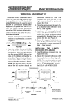
 ! ! ! " ! ! # ! # # ! !
WARNING
THIS UNIT AND ITS ASSOCIATED EQUIPMENT MUST BE INSTALLED,
ADJUSTED AND MAINTAINED BY QUALIFIED PERSONNEL WHO ARE
FAMILIAR WITH THE CONSTRUCTION AND OPERATION OF ALL EQUIPMENT
IN THE SYSTEM AND THE POTENTIAL HAZARDS INVOLVED. FAILURE TO
OBSERVE THESE PRECAUTIONS COULD RESULT IN BODILY INJURY.
WARNING
INSERTING OR REMOVING THIS MODULE OR ITS CONNECTING CABLES MAY
RESULT IN UNEXPECTED MACHINE MOVEMENT. TURN OFF POWER TO THE
MACHINE BEFORE INSERTING OR REMOVING THE UNIT OR ITS CONNECTING
CABLES. FAILURE TO OBSERVE THESE PRECAUTIONS COULD RESULT IN
BODILY INJURY.
! #
! ! #
# ! # Table of Contents
1.0
Introduction . . . . . . . . . . . . . . . . . . . . . . . . . . . . . . . . . . . . . . . . . . . . . . . 1Ć1
2.0
Mechanical/Electrical Description . . . . . . . . . . . . . . . . . . . . . . . . . . . 2Ć1
3.0
Installation . . . . . . . . . . . . . . . . . . . . . . . . . . . . . . . . . . . . . . . . . . . . . . . .
4.0
Diagnostics and Troubleshooting . . . . . . . . . . . . . . . . . . . . . . . . . . . . 4Ć1
3Ć1
Technical Specifications . . . . . . . . . . . . . . . . . . . . . . . . . . . . . . . . . . . . . . AĆ1
Platinum RTD TemperatureĆResistance Values European Curve . . . BĆ1
Field Connections . . . . . . . . . . . . . . . . . . . . . . . . . . . . . . . . . . . . . . . . . . . CĆ1
Related Components . . . . . . . . . . . . . . . . . . . . . . . . . . . . . . . . . . . . . . . . DĆ1
II
fafadfdfdasfdsfdsdsdfdsfdsfdsfsdfdsa
afdfdsfdsfdfdsfdsfsadfda
asfdfaddfdd
The 61C615 is an active termination panel that conditions and
powers 100 ohm platinum Resistance Temperature Detectors used
with the 61C613 analog input module.
Four input screw terminals are provided for each 3 wire RTD. A 4th
terminal is used to connect the RTD shield to a common ground.
This manual describes the functions and specifications of the panel.
It also describes how to install, set up, and service the panel.
Related publications that may be of interest:
D JĆ2605
AUTOMATER 30/40 PRODUCT SUMMARY
D JĆ2611
DCS 5000 PRODUCT SUMMARY
D JĆ3613Ć1 16 CHANNEL ANALOG INPUT MODULE
INSTRUCTION MANUAL
D IEEE 518 GUIDE FOR THE INSTALLATION OF
ELECTRICAL EQUIPMENT TO MINIMIZE
ELECTRICAL NOISE INPUTS TO
CONTROLLERS FROM EXTERNAL SOURCES
1Ć1
fafadfdfdasfdsfdsdsdfdsfdsfdsfsdfdsa
afdfdsfdsfdfdsfdsfsadfda
asfdfaddfdd
2.0 MECHANICAL/ELECTRICAL
DESCRIPTION
The following is a description of the termination connectors and
electrical characteristics of the field connections.
2.1
Mechanical Description
The 61C615 is a 19" rackĆmountable termination panel that includes
two 6Ćfoot, 50Ćwire twisted pair flat cables and a 6Ćfoot power cable. A
separately mounted +15 volt power supply is provided by the user.
Refer to figure 2.1. Panel dimensions are listed in Appendix A.
When the panel is viewed from the front, the flat cable on the right
side of the termination panel (TB2) is for analog inputs 8Ć15. It
connects to the bottom connector on the 61C613. The flat cable on
the left side of the termination panel (TB1) is for analog inputs 0Ć7. It
connects to the middle connector on the 61C613. The top connector
on the 61C613 module is not used.
The termination panel includes 64 clampĆtype screw terminals for
terminating field signals. A clear plastic shield is provided as a cover
for the terminal strips.
Figure 2.1Ć 61C615 Termination Panel
2.2
Electrical Description
The RTD termination panel is used to linearize and power 100 ohm
platinum Resistance Temperature Detectors used with the 61C613
analog input module. The resistance change of the RTD with
temperature is sensed by using the RTD as the external 4th arm of a
bridge. The termination panel contains the internal portions of the
bridge as well as the bridge excitation supply. See figure 2.2.
2Ć1
4
SHIELD
SENSE (LOW)
OUT A
OUT B
3
2
1
LOW R
LINEARITY
PART OF
INTERFACE
CABLE
HIGH R (GND)
SHIELD
SHIELD
10V
REF RANGE
Figure 2.2Ć Typical Input Circuit
A threeĆwire connection to each RTD allows the effects of lead
resistance (up to 5 ohms per lead) to be compensated out. A
separate shield connection is also provided. The shield is grounded
at the termination panel.
The supply for each bridge is modified by the output of a linearizing
amplifier to compensate for both bridge and RTD nonlinearities.
Three potentiometers are included for each channel to adjust offset,
range, and linearity. Nominal full scale is 200 mVolts for a 200 deg. C
span, or 100mVolts, depending upon how the panel is calibrated.
2Ć2
3.0 INSTALLATION
This section describes how to install and remove the termination
panel and its cable assembly.
3.1
Wiring
The installation of wiring should conform to all applicable codes.
To reduce the possibility of electrical noise interfering with the proper
operation of the control system, exercise care when installing the
wiring from the system to the external devices. For detailed
recommendations refer to IEEE 518.
3.2
Initial Installation
WARNING
THERE IS NO ISOLATION BETWEEN THE INDIVIDUAL CHANNELS ON THE
TERMINATION PANEL. DO NOT CONNECT DIFFERENT CHANNELS ON THE
SAME TERMINATION PANEL TO COMMON POINTS OF DIFFERENT
POTENTIALS. (FOR EXAMPLE, THIS PANEL SHOULD NOT BE CONNECTED TO
RTD DEVICES USED TO MONITOR MOTOR TEMPERATURES BECAUSE THE RTD
DEVICES WILL FLUCTUATE IN COMMON MODE VOLTAGE LEVEL BETWEEN THE
DIFFERENT MOTORS.) FAILURE TO OBSERVE THIS PRECAUTION MAY
DESTROY THE TERMINATION PANEL DUE TO EXCESSIVE CURRENTS FLOWING
IN THE COMMON WIRING.
Use the following procedure to install the module:
Step 1.
Turn off power to the system. All power to the rack as well
as all power to the wiring leading to the termination panel
should be off.
Step 2.
Mount the termination panel. It should be mounted to
permit easy access to the screw terminals on the terminal
board. Make certain that the terminal board is close
enough to the rack so that the cable will reach between
the terminal board and the module. The panel should be
located so that the flat cables can be routed to the front of
the module without coming in contact with high voltage
wires.
Step 3.
Mount the external power supply. It must be located within
a 6Ćft cable run of the termination panel. It should be
located so that the power cable can be routed to the
termination panel without coming in contact with high
voltage wires.
Step 4.
Connect the power cable on the termination panel to the
power supply.
Step 5.
Fasten field wires to the terminal strip. Make certain that all
field wires are securely fastened. The shield should be
terminated at the panel. Do not connect the shield at both
ends of the cable. Typical field signal connections are
shown in figure 3.1.
3Ć1
SENSE (LOW0
3 WIRE
100 OHM
RTD
LOW R
HIGH R (GND)
SHIELD
4
3
2
1
Figure 3.1 Ć Typical Field Signal Connections
Step 6.
Connect the 50Ćpin flat cables to their corresponding
connector on the analog input module (61C613). Attach
the cables by aligning the triangle marks on the cable end
and the board socket. Input channels 0Ć7 (TB1) use the
middle connector on the input module. Input channels
8Ć15 (TB2) use the bottom connector. If the rack contains
more than one analog input module, make certain that the
connectors are the proper ones for this module.
Step 7.
Turn on power to the system.
Step 8.
Verify the installation. Refer to the instruction manual for
the 16 Channel Analog Input Module (JĆ3613Ć1).
The termination panel is adjusted for European curve RTDs (alpha
temperature coefficient of 0.00385 ohms/ohm/degree C) and
includes an allowance for 0.1 ohm lead resistance. For lead
resistance greater than 0.1 ohm, the following procedure can be
used to calibrate the input for maximum accuracy:
1. The offset adjustment should not normally need further field
adjustment. If it becomes necessary, substitute a precision 100
ohm resistor in place of the RTD and adjust the offset
potentiometer for an output of zero volts. The offset
potentiometers are located at the back of the panel. Each
channel has a separate offset adjustment labeled OS".
2. Adjust the gain potentiometer so that total bridge voltage is
256.3mV across the 100 ohm resistor. The gain potentiometers
are located at the back of the panel. Each channel has a
separate gain adjustment labeled GN".
3Ć2
3. Force the RTD to a known temperature or simulate a known
temperature by connecting a precision resistor at the RTD end of
the field wiring. For example, if R = 182.0 ohms, then look up in
the table in Appendix B the resistor values above and below
182.0 ohms. With these values and their equivalent temperatures,
interpolate to find the expected temperature.
Deg. C
210
X
220
OHMS
179.51
182.0ă
183.17
ăăăăX = 216.80 deg. C
4. Adjust the linearity potentiometer for the corresponding
simulated temperature. The temperature should be at the upper
end of the operating range and must be well away from 0 deg C.
The linearity potentiometers are located at the back of the panel.
Each channel has a separate linearity adjustment labeled LI".
3.4
Panel Replacement
Use the following procedure to replace a termination panel:
Step 1.
Turn off power to the rack and all connections.
Step 2.
Use a screwdriver to loosen the screws holding the field
wires to the termination panel. Make certain that the wires
are tagged so that they can be replaced in the correct
order.
Step 3.
Remove the 50Ćpin flat cables from the back of the
termination panel.
Step 4.
Remove the termination panel.
Step 5.
Follow steps 2Ć6 in the installation procedure, section 3.2.
3Ć3
fafadfdfdasfdsfdsdsdfdsfdsfdsfsdfdsa
afdfdsfdsfdfdsfdsfsadfda
asfdfaddfdd
4.0 DIAGNOSTICS AND
TROUBLESHOOTING
For details on how to troubleshoot the termination panel, refer to the
instruction manual for the 16 Channel Analog Input Module
(JĆ3613Ć1).
4Ć1
fafadfdfdasfdsfdsdsdfdsfdsfdsfsdfdsa
afdfdsfdsfdfdsfdsfsadfda
asfdfaddfdd
Appendix A
Technical Specifications
Ambient Conditions
D Storage temperature: Ć40_C Ć 85_C
D Operating temperature: 0_C Ć 55_C
D Humidity: 5Ć90% nonĆcondensing
Dimensions
D Height: 1.7 inches
D Width: 19.0 inches
D Depth: 1.6 inches behind rack rails
2.5 inches in front of rack rails
Input Circuit
D Number of inputs: 16
D Type: 100 ohm (@ 0 degrees C) platinum RTD
D Resistance curve: European. Alpha = 0.00385 ohms/ohm/deg. C
D Isolation: All channels on panel have a common ground. Entire panel
may operate at nonĆzero common mode voltage
depending on input board common mode range and
power supply isolation.
D Connections: ScrewĆactivated, clamp type barrier strips. Accomodates 24
to 14 AWG wire. Four connections/RTD.
Output Circuit
D Linearized range: -20 to +250 deg. C
D Sensitivity: .5mVolt/deg. C
D Zero point: 0 deg. C
D Linearization error
for 0.1 ohm lead resistance: <0.1 deg. C (Ć20 to 250 deg.C)
for 0.1 to 0.2 ohm resistance: <0.1% reading + 0.1 deg. C
(-20 to 250 deg. C)
or
<.25 deg. C (-20 to 200 deg. C)
D Temperature variation (0Ć55 deg. C): 0.5% of reading, 0.2mVolts max
D Connections: 50 wire twisted pair flat cable per 8 channels, 6 ft long. One
end hardwired into panel; other end terminated in a
connector (3M part no. 3425Ć6050).
AĆ1
Appendix A
(Continued)
Power Requirements
+15 Volts: 100 mA
-15 Volts: 160 mA
Voltage tolerance: +1%
Voltage temp Coef.: 0.02%/deg.C
Line regulation: 0.1%
Load regulation: 0.1%
Ripple: <2 mVolts RMS
Protection: Each line fused at 1A and reverse voltage protected.
Fuse type: Littelfuse 276001
Connector: 3 wire cable, 6 ft. long with spad lugs
+15 Volts Ć yellow
-15 Volts Ć violet
ground Ć gray
WARNING
UNUSED INPUTS SHOULD BE CLOSED. OPEN INPUTS CAN CAUSE Ć15V
CURRENT TO INCREASE BY 15MA PER CHANNEL AND +15V CURRENT TO
INCREASE BY 10MA PER CHANNEL. JUMPER SENSE" TO HIGH R" (GROUND)
AT ALL UNUSED INPUTS. FAILURE TO OBSERVE THIS PRECAUTION COULD
RESULT IN BODILY INJURY OR DAMAGE TO EQUIPMENT.
AĆ2
Appendix B
Platinum RTD TemperatureĆResistance Values
European Curve
Alpha = 0.00385 ohms/ohm/deg.C
Deg.C
ohms
Deg.C
ohms
-150
39.65
180
168.47
-140
43.80
190
172.16
-130
47.93
200
175.84
-120
52.04
210
179.51
-110
56.13
220
183.17
-100
60.20
230
186.82
-90
64.25
240
190.46
-80
68.28
250
194.08
-70
72.29
260
197.70
-60
76.28
270
201.30
-50
80.25
280
204.88
-40
84.21
290
208.46
-30
88.17
300
212.03
-20
92.13
310
215.58
-10
96.07
320
219.13
0
100.00
330
222.66
10
103.90
340
226.18
20
107.79
350
229.69
30
111.67
360
233.19
40
115.54
370
236.67
50
119.40
380
240.15
60
123.24
390
243.61
70
127.07
400
247.06
80
130.89
410
250.50
90
134.70
420
253.93
100
138.50
430
257.34
110
142.28
440
260.75
120
146.06
450
264.14
130
149.82
460
267.52
140
153.57
470
270.89
150
157.32
480
274.25
160
161.05
490
277.60
170
164.76
500
280.93
BĆ1
fafadfdfdasfdsfdsdsdfdsfdsfdsfsdfdsa
afdfdsfdsfdfdsfdsfsadfda
asfdfaddfdd
Appendix C
Field Connections
TB1
TB2
1
Pin
32
Channel
1
Input
Pin
32
Channel
Input
1
2
3
4
0
0
0
0
Shield
High R
Low R
Sense
1
2
3
4
8
8
8
8
Shield
High R
Low R
Sense
5
6
7
8
1
1
1
1
Shield
High R
Low R
Sense
5
6
7
8
9
9
9
9
Shield
High R
Low R
Sense
9
10
11
12
2
2
2
2
Shield
High R
Low R
Sense
9
10
11
12
10
10
10
10
Shield
High R
Low R
Sense
13
14
15
16
3
3
3
3
Shield
High R
Low R
Sense
13
14
15
16
11
11
11
11
Shield
High R
Low R
Sense
17
18
19
20
4
4
4
4
Shield
High R
Low R
Sense
17
18
19
20
12
12
12
12
Shield
High R
Low R
Sense
21
22
23
24
5
5
5
5
Shield
High R
Low R
Sense
21
22
23
24
13
13
13
13
Shield
High R
Low R
Sense
25
26
27
28
6
6
6
6
Shield
High R
Low R
Sense
25
26
27
28
14
14
14
14
Shield
High R
Low R
Sense
29
30
31
32
7
7
7
7
Shield
High R
Low R
Sense
29
30
31
32
15
15
15
15
Shield
High R
Low R
Sense
n.c.
n.c.
n.c.
n.c.
33
34
35
36
33
34
35
36
n.c.
n.c.
n.c.
n.c.
R = resistance n.c. = no connection
CĆ1
fafadfdfdasfdsfdsdsdfdsfdsfdsfsdfdsa
afdfdsfdsfdfdsfdsfsadfda
asfdfaddfdd
fafadfdfdasfdsfdsdsdfdsfdsfdsfsdfdsa
afdfdsfdsfdfdsfdsfsadfda
asfdfaddfdd
fafadfdfdasfdsfdsdsdfdsfdsfdsfsdfdsa
afdfdsfdsfdfdsfdsfsadfda
asfdfaddfdd
For additional information
1 Allen-Bradley Drive
Mayfield Heights, Ohio 44124 USA
Tel: (800) 241-2886 or (440) 646-3599
http://www.reliance.com/automax
Publication J-3645-2 - January 1991
Copyright © 2002 Rockwell Automation, Inc.. All rights reserved. Printed in U.S.A.