1
The information in this user's manual is subject to change without notice.
WARNING
THIS UNIT AND ITS ASSOCIATED EQUIPMENT MUST BE INSTALLED,
ADJUSTED AND MAINTAINED BY QUALIFIED PERSONNEL WHO ARE
FAMILIAR WITH THE CONSTRUCTION AND OPERATION OF ALL EQUIPMENT
IN THE SYSTEM AND THE POTENTIAL HAZARDS INVOLVED. FAILURE TO
OBSERVE THESE PRECAUTIONS COULD RESULT IN BODILY INJURY.
WARNING
INSERTING OR REMOVING THIS MODULE OR ITS CONNECTING CABLES MAY
RESULT IN UNEXPECTED MACHINE MOTION. POWER TO THE MACHINE
SHOULD BE TURNED OFF BEFORE INSERTING OR REMOVING THE MODULE
OR ITS CONNECTING CABLES. FAILURE TO OBSERVE THESE PRECAUTIONS
COULD RESULT IN BODILY INJURY.
CAUTION
THIS MODULE CONTAINS STATICĆSENSITIVE COMPONENTS. CARELESS
HANDLING CAN CAUSE SEVERE DAMAGE.
DO NOT TOUCH THE CONNECTORS ON THE BACK OF THE MODULE. WHEN
NOT IN USE, THE MODULE SHOULD BE STORED IN AN ANTIĆSTATIC BAG. THE
PLASTIC COVER SHOULD NOT BE REMOVED. FAILURE TO OBSERVE THIS
PRECAUTION COULD RESULT IN DAMAGE TO OR DESTRUCTION OF THE
EQUIPMENT.
Toledo Scale is a trademark of Toledo Scale, Inc.
Reliance is a registered trademark of Reliance Electric Company or its subsidiaries.
Copyright Reliance Electric Industrial Company 1991.
Table of Contents
1.0
Introduction . . . . . . . . . . . . . . . . . . . . . . . . . . . . . . . . . . . . . . . . . . . . . . . 1Ć1
2.0
Mechanical/Electrical Description . . . . . . . . . . . . . . . . . . . . . . . . . . . 2Ć1
$ " (' &) %$ .
")' " (' &) %$ .
3.0
Installation . . . . . . . . . . . . . . . . . . . . . . . . . . . . . . . . . . . . . . . . . . . . . . . .
' $ $ ) " $()"") %$ %*" &"#$) 3Ć1
.
.
.
4.0
Programming . . . . . . . . . . . . . . . . . . . . . . . . . . . . . . . . . . . . . . . . . . . . . .
()' '$ -) %$ ))*( $ %$)'%" ()'( %"% " ) ()'( %$ *') %$ $ ) $ &&" ) %$ (!( %$ *' $ ) %*" $ ) ) (( '$(# (( %$ # ()' ) %$( #%) !( $ %"% " ) ' ) $ ) )% ()'( 4Ć1
.
.
.
.
.
.
.
.
.
.
.
.
5.0
Diagnostics and Troubleshooting . . . . . . . . . . . . . . . . . . . . . . . . . . . .
% ) + ), %$ ' " $ $%'') ) *( ''%' 5Ć1
.
.
.
Technical Specifications . . . . . . . . . . . . . . . . . . . . . . . . . . . . . . . . . . . . . . AĆ1
Module Block Diagram . . . . . . . . . . . . . . . . . . . . . . . . . . . . . . . . . . . . . . BĆ1
Field Connections . . . . . . . . . . . . . . . . . . . . . . . . . . . . . . . . . . . . . . . . . . . CĆ1
Toledo Scale Continuous Output Message Format . . . . . . . . . . . . . . DĆ1
Defining Variables in the Configuration Task . . . . . . . . . . . . . . . . . . . . EĆ1
II
Figure 2.1
Figure 2.2
Ć Module Faceplate . . . . . . . . . . . . . . . . . . . . . . . . . . . . . . . . . . . . . 2Ć2
Ć LED Fault Codes . . . . . . . . . . . . . . . . . . . . . . . . . . . . . . . . . . . . . . 2Ć3
Figure 3.1
Figure 3.2
Figure 3.3
Ć Typical Field Signal Connections . . . . . . . . . . . . . . . . . . . . . . . . 3Ć1
Ć Toledo Scale Digital Indicator Xmit Connector . . . . . . . . . . . . 3Ć2
Ć Rack Slot Numbers . . . . . . . . . . . . . . . . . . . . . . . . . . . . . . . . . . . 3Ć2
Figure 4.1
Figure 4.2
Figure 4.3
Figure 4.4
Figure 4.5
Figure 4.6
Figure 4.7
Figure 4.8
Figure 4.9
Figure 4.10
Figure 4.11
Figure 4.12
Ć
Ć
Ć
Ć
Ć
Ć
Ć
Ć
Ć
Ć
Ć
Ć
Figure 5.1
Ć Pulse Time for Different Baud Rates . . . . . . . . . . . . . . . . . . . . . 5Ć1
Dual Port Memory Organization . . . . . . . . . . . . . . . . . . . . . . . . .
Status and Control Registers . . . . . . . . . . . . . . . . . . . . . . . . . . .
Receive Message Status . . . . . . . . . . . . . . . . . . . . . . . . . . . . . . .
Configuration/Update Request Register . . . . . . . . . . . . . . . . . .
Control Registers . . . . . . . . . . . . . . . . . . . . . . . . . . . . . . . . . . . . .
Request/Status Register Error Codes . . . . . . . . . . . . . . . . . . . .
Message Counter Register . . . . . . . . . . . . . . . . . . . . . . . . . . . . .
Status Byte A" . . . . . . . . . . . . . . . . . . . . . . . . . . . . . . . . . . . . . . . .
Status Byte B" . . . . . . . . . . . . . . . . . . . . . . . . . . . . . . . . . . . . . . .
Status Byte C" . . . . . . . . . . . . . . . . . . . . . . . . . . . . . . . . . . . . . . .
Weight and Tare Registers . . . . . . . . . . . . . . . . . . . . . . . . . . . . .
Setpoint Flag Register . . . . . . . . . . . . . . . . . . . . . . . . . . . . . . . . .
4Ć1
4Ć1
4Ć2
4Ć2
4Ć3
4Ć4
4Ć4
4Ć5
4Ć5
4Ć6
4Ć6
4Ć6
III
fafadfdfdasfdsfdsdsdfdsfdsfdsfsdfdsa
afdfdsfdsfdfdsfdsfsadfda
asfdfaddfdd
The products described in this instruction manual are manufactured
or distributed by Reliance Electric Company or its subsidiaries.
The Toledo Scale Interface Module provides a single RSĆ232C serial
I/O port for receiving data from Toledo Scale digital indicators (model
numbers 8132, 8140, 8142, and 8530) that communicate via
RSĆ232C with the Toledo Scale Continuous Output protocol. The
serial data is stored in dual port memory where it can be read by
application software.
This manual describes the functions and specifications of the
module. It also includes a detailed overview of installation and
servicing procedures, as well as examples of programming methods.
Related publications that may be of interest:
JĆ3630
AutoMax PROGRAMMING EXECUTIVE
INSTRUCTION MANUAL VERSION 1.0
JĆ3649
AutoMax CONFIGURATION TASK MANUAL
JĆ3650
AutoMax PROCESSOR MODULE
INSTRUCTION MANUAL
JĆ3675
AutoMax ENHANCED BASIC LANGUAGE
INSTRUCTION MANUAL
JĆ3676
AutoMax CONTROL BLOCK LANGUAGE
INSTRUCTION MANUAL
JĆ3677
AutoMax LADDER LOGIC LANGUAGE
INSTRUCTION MANUAL
JĆ3684
AutoMax PROGRAMMING EXECUTIVE
INSTRUCTION MANUAL VERSION 2.0
JĆ3750
ReSource AutoMax PROGRAMMING EXECUTIVE
INSTRUCTION MANUAL VERSION 3.0
IEEE 518 GUIDE FOR THE INSTALLATION OF
ELECTRICAL EQUIPMENT TO MINIMIZE
ELECTRICAL NOISE INPUTS TO
CONTROLLERS FROM EXTERNAL SOURCES
1Ć1
fafadfdfdasfdsfdsdsdfdsfdsfdsfsdfdsa
afdfdsfdsfdfdsfdsfsadfda
asfdfaddfdd
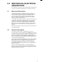
2.0 MECHANICAL/ELECTRICAL
DESCRIPTION
The following is a description of the faceplate LEDs, field termination
connectors, and electrical characteristics of the field connections.
2.1
Mechanical Description
The Toledo Scale Interface module is a printed circuit board
assembly that plugs into the backplane of the DCS5000/AutoMax
rack. It consists of a printed circuit board, a faceplate, and a
protective enclosure. The faceplate contains tabs at the top and
bottom to simplify removing the module from the rack. Module
dimensions are listed in Appendix A.
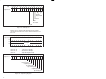
The faceplate of the module contains a 25 pin D" shell connector for
an RSĆ232C serial I/O link. For diagnostic purposes, the faceplate
contains one sevenĆsegment LED and a green status light that
indicates when the board is operational (ON) or malfunctioning
(OFF). There are also two thumbwheel switches on the faceplate of
the module. These switches are not used in this application. See
figure 2.1.
The back of the module contains two edge connectors that attach to
the system backplane.
2.2
Electrical Description
The interface module contains a 4 mhz Z80 microprocessor.
Processor memory consists of 16K bytes of EPROM memory for the
communication software, 8K bytes of RAM for local data storage, and
4K words of dual port memory. The module is equipped with a
RSĆ232C serial I/O port, a programmable baud rate generator, and
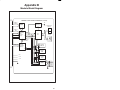
the necessary circuitry to interface with the system backplane. Refer
to the block diagram in Appendix B.
This module also contains a watchdog timer, used to detect hardware
failures. The watchdog is enabled whenever power is turned on to
the module. If a processor is unable to reset the watchdog, an
interrupt will be generated to stop the processor. The dual port
memory will be disabled so that it cannot be accessed by the user's
application software.
There is one green status light and one 7Ćsegment LED on the
faceplate of the module. The status light is labeled OK". When the
light is on, the module has passed its powerĆup diagnostics and the
watchdog timer has not timed out.
2Ć1
TOLEDO
SCALE
INTERFACE
FAULT
CODE
OK
DROP
NUMBER
0
1ST
0
2ND
Figure 2.1Ć Module Faceplate
2Ć2
The 7Ćsegment LED provides detailed information on the status of the
module. If the LED displays any number from 0" through 9"
inclusive or b," the module is malfunctioning and has not passed
one of its powerĆup diagnostics. Three other possible displays
indicate that the module has not been set up properly or that there is
a fault somewhere else in the system. See figure 2.2 for an
explanation of fault codes.
Fault
Code
Explanation
0
CPU failed powerĆup diagnostic
1
EPROM failed powerĆup diagnostic
2
RAM failed powerĆup diagnostic
3
CTC failed powerĆup diagnostic
4
SIO failed powerĆup diagnostic
6
DPM failed powerĆup diagnostic
7
MMU failed powerĆup diagnostic
9
PIO failed powerĆup diagnostic
b
Watchdog failed powerĆup diagnostic
C
Communication line status. Displayed only if the link has
not been configured by a DCS application task.
d
System (backplane) watchdog failed. Board is operational
but will not receive data until the watchdog is reset.
E
Power failure. This code is normally displayed from the
time that a power failure is detected until power is lost.
Figure 2.2 Ć LED Fault Codes
2Ć3
fafadfdfdasfdsfdsdsdfdsfdsfdsfsdfdsa
afdfdsfdsfdfdsfdsfsadfda
asfdfaddfdd
3.0 INSTALLATION
This section describes how to install and remove the module and its
cable assembly.
3.1
Wiring
The installation of wiring should conform to all applicable codes.
To reduce the possibility of electrical noise interfering with the proper
operation of the control system, exercise care when installing the
wiring from the system to the external devices. For detailed
recommendations refer to IEEE 518.
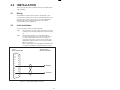
3.2
Initial Installation
Use the following procedure to install the module:
Step 1.
Turn off power to the system. All power to the rack as well
as all power to the wiring leading to the module should be
off.
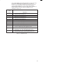
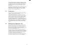
Step 2.
Fasten the two field wires to a 25 pin male DĆshell
connector. Typical field connections are shown in figure
3.1. Make certain that the other end of the cable is
connected to the proper connector on the Toledo Scale
digital indicator. Refer to figure 3.2 for the proper digital
indicator connection.
Refer to Appendix C for the arrangement of terminal board
connections. All field wires should be fastened securely.
25 PIN
MALE CONNECTOR
13
12
11
10
9
8
7
6
5
4
3
2
1
TOLEDO SCALE
DIGITAL INDICATOR
25
24
23
22
21
20
GROUND
19
18
17
16
TRANSMIT
15
14
Figure 3.1 Ć Typical Field Signal Connections
3Ć1
Model
Connector
8132
J19
8140
J7 or J12
8142
JN
8530
JN
Figure 3.2Ć Toledo Scale Digital Indicator Xmit Connector
Step 3.
Take the module out of its shipping container. Take it out of
the antiĆstatic bag, being careful not to touch the
connectors on the back of the module.
Step 4.
Insert the module into the desired slot in the rack. Refer to
figure 3.3. Use a screwdriver to secure the module into the
slot.
Typical 16 Slot Rack
16
Typical 10 Slot Rack
P/S
0
1
2
10
3
4
5
6
7
8
9
10 11 12 13 14 15
Figure 3.3 Ć Rack Slot Numbers
3Ć2
Step 5.
Connect the DĆshell on the end of the field wires to the
connector on the faceplate of the module. Use a
screwdriver to secure the connector to the module.
Step 6.
Turn on power to the system.
Step 7.
Verify the installation by checking the status of the
sevenĆsegment LED and the OK" light. When the power
is turned on, the module will automatically execute its
powerĆup diagnostics. After the module has finished its
diagnostics, the sevenĆsegment LED on the faceplate
should be off if the diagnostics were completed
successfully. The link is configured for 4800 baud on
powerĆup. The green OK" light should be on in either
case.
Step 8.
Connect the programmer to the system and run the
ReSource Software. Use the I/O MONITOR function.
If a baud rate other than 4800 is required, configure the
serial port by writing the baud rate used by the
transmitting device to register 21 and then writing the
value 255 to register 20. The sevenĆsegment LED should
now be blank.
Monitor registers 14,16,17 and 18 using the ReSource
Software. Register 14 should be changing at the rate that
messages are being received.
Use the following procedure to replace a module:
Step 1.
Turn off power to the rack and all connections.
Step 2.
Use a screwdriver to loosen the screws holding the
connector to the module. Remove the connector from the
module.
Step 3.
Loosen the screws that hold the module in the rack.
Remove the module from the slot in the rack.
Step 4.
Place the module in the antiĆstatic bag it came in, being
careful not to touch the connectors on the back of the
module. Place the module in the cardboard shipping
container.
Step 5.
Take the new module out of the antiĆstatic bag, being
careful not to touch the connectors on the back of the
module.
Step 6.
Insert the module into the desired slot in the rack. Use a
screwdriver to secure the module into the slot.
Step 7.
Attach the DĆshell connector to the mating half on the
module. Make certain that the connector is the proper one
for this module. Use a screwdriver to secure the connector
to the module.
Step 8.
Turn on power to the rack.
3Ć3
fafadfdfdasfdsfdsdsdfdsfdsfdsfsdfdsa
afdfdsfdsfdfdsfdsfsadfda
asfdfaddfdd
4.0 PROGRAMMING
This section describes how data is organized in the module and
provides examples of how the module is accessed by the application
software. For more detailed information refer to the AutoMax
Enhanced BASIC Language Instruction Manual (JĆ3675).
4.1
Register Organization
The Toledo Scale Interface module contains a dual port memory that
can be accessed by your application software as well as the
microprocessor that controls the module. The dual port memory
contains the control and status information as well as the Toledo
Scale data. See figure 4.1 for the dual port memory map.
Register 0
through
Register 39
Status and Control
Register 64
through
Register 77
Toledo Scale Data
Figure 4.1Ć Dual Port Memory Organization
4.1.1
Status and Control Registers
Use the status and control registers to configure the serial
communication port and then monitor its operation. All registers are
readĆonly with the exception of registers 20Ć39.
Register 4 contains the link configuration status. It will be set to 1"
after you have properly configured the module. Refer to figure 4.2.
bits
register 4
15 14 13 12 11 10
-
-
-
-
-
-
9
8
7
6
5
4
3
2
1
0
-
-
-
-
-
-
-
-
-
R
ąą ąLink Status
0 Ć not configured
1 Ć configured
Figure 4.2Ć Status and Control Registers
4Ć1
Registers 14 through 18 contain information on the number and
quality of messages received on the serial link. These counters will be
incremented only if the startĆofĆmessage character (STX) is
recognized by the module. Typically, these registers are used for
diagnosing the serial link when problems occur. Refer to figure 4.3.
bits
15 14 13 12 11 10
register 14
9
8
7
6
5
4
3
2
1
0
number of good messages received
15
not used
16
number of checksum or parity errors
17
number of overrun errors
18
number of framing errors
Figure 4.3Ć Receive Message Status
Register 20 is the configuration/update request register. The module
continually monitors this register, and will reĆconfigure the link
anytime the update flag is set. Refer to figure 4.4.
bits
register 20
15 14 13 12 11 10
-
-
-
-
-
-
9
8
-
0
7
6
5
4
3
2
1
0
update request
NonĆzero for update request
Figure 4.4 Ć Configuration/Update Request Register
Register 21 defines the serial port baud rate. The baud rate may be
1200, 2400, 4800, 9600 or 19,200. Refer to figure 4.5.
Register 22 defines the link inactive" timeĆout value to aid the user in
detecting link failures. Each time a startĆofĆmessage character (STX)
is received, a timer is initiated with this value. If the timer expires, the
next request by the application program for the scale data will result
in link inactive" status being returned. The timeĆout value is specified
in seconds with a minimum value of one and a maximum value of 10.
The default value is five. See figure 4.5.
4Ć2
bits
15 14 13 12 11 10
register 21
9
8
7
6
5
4
3
2
1
0
baud rate (1200Ć9600)
link timeĆout (1Ć10 seconds)
22
Figure 4.5Ć Control Registers
register 23
register 24, 25
register 26, 27
register 28, 29
register 30, 31
register 32, 33
register 34, 35
register 36, 37
register 38, 39
Ć
Ć
Ć
Ć
Ć
Ć
Ć
Ć
Ć
Setpoint Update Request
Setpoint #1
Setpoint #2
Setpoint #3
Setpoint #4
Setpoint #5
Setpoint #6
Setpoint #7
Setpoint #8
Registers 24 through 39 may contain eight doubleĆinteger Setpoint
values. The Setpoint values must be specified with the same implied
decimal point as the Indicated Weight from the Indicator. The values
are first stored in registers 24 to 39. Then register 23 must be set to a
nonĆzero value to initiate the update in the Interface. The Interface
software will set register 23 to a zero value after the update is
complete. Setpoint values may be changed at any time, but you must
to set register 23 to initiate the update. The Setpoints are initialized to
zero on powerĆup.
4.1.2
Toledo Scale Data Registers
The Toledo Scale status and weight data registers contain the data
transmitted from the Toledo Scale digital indicator. All registers are
readĆonly with the exception of register 64.
Register 64 is used to initiate an update of registers 65Ć77. In order to
read the scale data (status and weight), first set the request/status
register to a value of one. Next, monitor the register for a value less
than or equal to zero. A value of zero indicates valid data which may
be read by the BASIC task. A negative value in the request/status
register indicates an error condition. Refer to figure 4.6 for an
explanation of error codes for register 64.
Data is received continuously by the module. The data is placed in
dual port memory only when requested via the request/status
register (register 64). The data that will be stored in dual port memory
will be the last valid message that was received by the module.
Registers 66Ć77 are not updated if an error status is returned.
4Ć3
bits
15 14 13 12 11 10
register 64
9
8
7
6
5
4
3
2
1
0
request/status
Value
ă1 = User request to update information in registers 65Ć77.
ă0 = Update completed without error.
-1 = The checksum calculated by the module did not match the
checksum character in the received message.
-2 = A nonĆnumeric character was detected when converting the
Indicated Weight or Tare Weight data to binary.
-3 = A message with valid startĆofĆmessage and endĆofĆmessage
characters did not contain 18 bytes.
-4 = No link activity. A startĆofĆmessage character was not received in
the time specified in Register 22.
-5 = A positive value greater than one was detected in the request/
status register.
-6 = A checksum character was not received within 16 msec. after a
valid endĆofĆmessage character was received. Check that the
scale is configured for transmitting a checksum.
Figure 4.6 Ć Request/Status Register Error Codes
Register 65 is incremented by the module each time it receives a
startĆofĆmessage character on the serial interface. The value will
range from 0 Ć 255. Use this register to determine whether the data
contained in registers 66Ć77 has changed from the last time it was
read. Refer to figure 4.7.
bits
register 65
15 14 13 12 11 10
0
0
0
0
0
0
9
8
0
0
7
6
5
4
3
2
message counter
Figure 4.7 Ć Message Counter Register
Registers 66Ć72 contain the data that was received in the last
message from the Toledo Scale digital indicator.
4Ć4
1
0
Register 66 contains status byte A". Refer to figure 4.8.
bits
register 66
15 14 13 12 11 10
-
-
-
-
-
-
9
8
7
6
5
4
3
2
1
0
-
-
-
R
1
R
R
R
R
R
Decimal pt.
Location
0 = x100
1 = x10
2 = x1
3 = x.1
4 = x.01
5 = x.001
6 = x.0001
7 = x.00001
Model
Dependent
Model
Dependent
Model
Dependent
Figure 4.8Ć Status Byte A"
Register 67 contains status byte B". Refer to figure 4.9.
bits
register 67
15 14 13 12 11 10
9
8
7
6
5
4
3
2
1
0
-
-
-
-
R
1
R
R
R
R
R
-
-
-
-
-
Model Dependent
Units
0 = pounds
1 = kilograms
Motion
0 = no motion
1 = in motion
Range
0 = in range
1 = overrange
Weight is
0 = Positive
1 = Negative
Mode
0 = Gross
1 = Net
Figure 4.9Ć Status Byte B"
4Ć5
Register 68 contains status byte C". Refer to figure 4.10.
bits
register 68
15 14 13 12 11 10
-
-
-
-
-
-
9
8
7
6
5
4
3
2
1
0
-
-
-
R
1
R
R
R
R
R
Model
Dependent
Print Button
Pushed
Model
Dependent
Model
Dependent
Figure 4.10Ć Status Byte C"
Registers 69Ć72 contain the indicated weight and tare weight,
respectively. These values are stored as 32Ćbit long integers. See
figure 4.11.
bits
15 14 13 12 11 10
register 69
9
8
7
6
5
4
3
2
1
0
3
2
1
0
Indicated Weight
70
71
Tare Weight
72
Figure 4.11Ć Weight and Tare Registers
register 73, 74
register 75, 76
register 77
bits
Ć
Ć
Ć
15 14 13 12 11 10
`signed' Gross Weight
absolute Gross Weight
Setpoint Comparison Flags
9
8
7
6
5
4
register 77
setpoint flag #8
setpoint flag #7
setpoint flag #6
setpoint flag #5
setpoint flag #4
setpoint flag #3
setpoint flag #2
setpoint flag #1
Figure 4.12Ć Setpoint Flag Register
4Ć6
Two Gross Weight calculations are made by the Interface software.
The `signed' Gross Weight is computed by first applying the `sign' bit
from Status Word `B' to the Indicated Weight and then adding the
Tare Weight. The result is stored as a double integer in registers 73,
74. The absolute value of the `signed' Gross Weight is stored in
registers 75, 76.
A comparison of the `signed' Gross Weight is made with each of the
eight Setpoints in registers 24Ć39. If the `signed' Gross Weight is less
than the Setpoint, the flag bit in register 77 is set to a 1 (TRUE);
otherwise, the bit is set to zero (FALSE). The comparison flag for
Setpoint #1 is in bit 0, Setpoint #2 in bit 1, etc.
4.2
Configuration
Before any application programs can be written, it in necessary to
configure, or set, the definitions of systemĆwide variables, i.e. those
that must be globally accessible to all tasks.
For DCS 5000 and AutoMax Version 2.1 and earlier, you define
systemĆwide variables by writing a Configuration task. For AutoMax
Version 3.0 and later, you define systemĆwide variables using the
AutoMax Programming Executive. After these variables are defined,
you can generate the configuration file automatically, which
eliminates the requirement to write a configuration task for the rack. If
you are using AutoMax version 2.1 or earlier, refer to Appendix E for
examples that show how to define variables in the configuration task.
If you are using AutoMax Version 3.0 or later, see the AutoMax
Programming Executive (JĆ3750) for information about configuring
variables.
4.3
Reading Data in Application Tasks
The frequency with which tasks read their inputs depends on the
language being used. Ladder logic and control block tasks read
inputs once at the beginning of each scan and write outputs once at
the end of each scan, regardless of how often the inputs are
referenced in the task. BASIC tasks read an input and write an output
for each reference throughout the scan.
In order for the interface module to be referenced by application
software it is necessary to assign symbolic names to the registers on
the module. In AutoMax Version 2.1 and earlier, this is accomplished
by IODEF statements in the configuration task. Refer to Appendix E
for a example. In AutoMax Version 3.0 and later,you can assign
symbolic names using the Programming Executive.
Each application task that references the symbolic names assigned
to the interface module must declare those names COMMON.
4Ć7
4.3.1
Configuring the Module
The module must be configured whenever you turn on power to the
system or change the baud rate of the serial interface. If the module
has not been configured, it will display the letter C" on its LED. The
following is an example of the BASIC statements required in an
application task to configure the module.
400
410
420
430
440
450
480
490
600
610
620
630
1000
1010
1020
1030
1040
1050
1060
1070
4.3.2
COMMON LINK_STATUS@
\!Link configuration status
COMMON LINK_CONF%
\!Link configuration request
COMMON BAUD_RATE%
\!Baud rate
COMMON RQST_STATUS%
\!Message request
COMMON MSG_NO%
\!Message number
COMMON STATUS_A%
\!Status byte A
COMMON INDICATED_WT!
\!Indicated weight
COMMON TARE_WEIGHT!
\!Tare weight
LOCAL
OLD_MSG_NO%
\!Old data check
LOCAL
WEIGHT
\!Weight in eng units
LOCAL
TARE
\!Tare weight in eng units
LOCAL
EXPONENT
\!Power of ten scaling
REM
REM Initialize Interface Ć Execute this section only 1 time
REM
BAUD_RATE% = 9600
LINK_CONF% = 00FFH
\!Request link configuration
DELAY 1 TICK
\!Wait for link config.
IF NOT LINK_STATUS@ THEN 1050
OLD_MSG_NO% = -1
\!For old" data check
Reading the Data
The following is an example of the BASIC statements required to read
the data from the module:
2000
2010
2020
2030
2047
2048
2049
2050
2055
2060
2070
2075
2080
2085
2090
2095
2100
2105
2110
2500
3000
3100
3200
3300
4Ć8
RQST_STATUS% = 1
\! Set request flag for data
DELAY 1 TICK
IF RQST_STATUS% = 1 THEN 2010
\! Check for returned status
IF RQST_STATUS% < 0 THEN 3000
\! Branch if error
REM
REM Valid data, process weight data
REM
IF MSG_NO% = OLD_MSG_NO% THEN 2110
REM
\! If old data, skip conversion
OLD_MSG_NO% = MSG_NO%
\! Update old message number
EXPONENT=10.**(2-(STATUS_A% AND 07H))
REM
\! Get power of 10
IF EXPONENT > 1. THEN EXPONENT = 1.0
REM
\! If x1 or more, no scaling req'd
WEIGHT = INDICATED_WT! * EXPONENT
REM
\! Convert weight data to REAL
TARE = TARE_WEIGHT! * EXPONENT
REM
\! & account for decimal point
!
!
!ąError status returned
!
!ąDecode error status
END
4.4
Message Transmission Time
The time required for a message to be transmitted is:
Time (in milliseconds) = 198,000/Baud Rate
The module requires less than 1 millisecond to receive the message
and store it in dual port memory.
4.5
Restrictions
This section describes limitations and restrictions on the use of this
module.
4.5.1
Remote Racks
This module should not be used in a remote rack.
4.5.2
Reading Toledo Scale Data
Registers 65Ć72 should not be read without first performing a
request update" via register 64.
4.5.3
Writing Data to Registers
This module contains registers that are read only. Attempts to write to
them will cause a bus error (severe system error). The following are
examples from programs that write to the module and should
therefore be avoided if they involve readĆonly registers:
a. Referencing the module from the coil in a ladder logic task.
b. Referencing the module on the left side of an equal sign in a LET
statement in a control block or BASIC task.
c.
Referencing the module as an output in a control block function.
4Ć9
fafadfdfdasfdsfdsdsdfdsfdsfdsfsdfdsa
afdfdsfdsfdfdsfdsfsadfda
asfdfaddfdd
5.0 DIAGNOSTICS AND
TROUBLESHOOTING
This section explains how to troubleshoot the module and field
connections. If you cannot determine the problem, the unit is not
userĆserviceable.
5.1
No Activity on Serial Line
Problem: No data is being received on the serial line. You can
confirm this by monitoring the values in register 14Ć18. If they do not
change regularly, no data is being received. The possible causes of
this error are a programming error or a malfunctioning module. It is
also possible that the transmitter is malfunctioning, or that the serial
line is not connected or is connected to the wrong transmitter. Use
the following procedure to isolate the problem:
Step 1.
Verify that the module has been configured correctly.
The LED on the module faceplate should be blank. If it is,
verify that the baud rate in register 21 is the same as the
baud rate of the transmitting device.
If the LED on the module faceplate displays the letter C,"
the module has not been configured correctly. Review
your rack configuration as well as the programming
statements to configure the module.
Step 2.
Verify that the module is connected to the correct
transmitter.
Check the cabling between the module and the
transmitter. Make certain that the proper devices are
connected together, that all the connections are secure,
and that the proper signals are connected together. Refer
to Appendix C for DĆshell connections and to figure 4 for
the proper connector on the transmitting device.
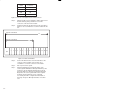
Step 3.
Verify that the serial link is working.
Connect an oscilloscope to the transmitter terminals on
the Toledo Scale digital indicator. The oscilloscope should
display a square wave with periods equal to the values in
figure 5.1 when the device is transmitting. If it does not
display a square wave, the transmitter is malfunctioning.
Volts
time
ąąą1200 baud = 833 microseconds
ąąą2400 baud = 417 microseconds
ąąą4800 baud = 208 microseconds
ąąą9600 baud = 104 microseconds
ąąă19200 baud = ă52 microseconds
Figure 5.1Ć Pulse Time for Different Baud Rates
5Ć1
If the transmitter is working correctly, repeat this process
on the connector on the interface module. If the
oscilloscope displays a square wave again, the interface
module is malfunctioning. Otherwise, troubleshoot the
cabling.
Problem: The data is either always off, always on, or different than
expected. The possible causes of this problem are a module in the
wrong slot, a programming error, or a malfunctioning module. It is
also possible that the input is not wired or is wired to the wrong
device. Use the following procedure to isolate the problem:
Step 1.
Verify that the serial link is working correctly.
Refer to the procedure in section 5.1.
Step 2.
Verify that the input module is in the correct slot.
Refer to figure 3.3. Verify that the slot number being
referenced agrees with the slot number defined in the
configuration. Verify that the register numbers that have
been assigned to the variables agree with the definitions in
the configuration task.
Step 3.
Verify that the module can be accessed.
Connect the programmer to the system and run the
ReSource Software.
Stop all tasks that may be running.
Using the I/O MONITOR, toggle register 64 and verify that
the data in register 65 changes and that the data in
registers 65Ć72 is the correct scale data.
If the programmer is able to read the data, the problem
lies in the application software (refer to step 4). If the
programmer cannot read the data, the problem lies in the
hardware (refer to step 5).
Step 4.
Verify that the user application program is correct.
Verify that the application program that uses the symbolic
names assigned to the module has defined them as
COMMON.
Compare your application program with the examples
given in sections 4.3.2 and 4.3.3. In your program, make
certain that you are toggling register 64 before attempting
to read the data in registers 65Ć72.
Step 5.
Verify that the hardware is working correctly.
Verify the hardware functionality by systematically
swapping out modules. After each swap, if the problem is
not corrected, replace the original module before
swapping out the next module.
First, replace the input module. Next, replace the
Processor module (s). If the problem persists, take all of
the modules out the backplane except one Processor
module and the interface module. If the problem is now
corrected, one of the other modules in the rack is
malfunctioning. Reconnect the other modules one at a
5Ć2
time until the problem reappears. If none of these tests
reveals the problem, replace the backplane.
Problem: A 31" or 51"Ć54" appear on the processor module`s
LED. These error messages indicate that there was a bus error when
the system attempted to access the module. The possible causes of
this error are a missing module, a module in the wrong slot, or a
malfunctioning module. It is also possible that the user is attempting
to write to readĆonly registers on the module. Use the following
procedure to isolate a bus error:
Step 1.
Verify that the input module is in the correct slot.
Refer to figure 3.3. Verify that the slot number being
referenced agrees with the slot number defined in the
configuration task. Verify that the register numbers that
have been assigned to the variables agree with the
definitions in the configuration task.
Step 2.
Verify that the module can be accessed.
Connect the programmer to the system and run the
ReSource Software. Monitor register 14 on the module. If
the programmer is able to monitor it, the problem lies in
the application software (refer to step 3). If the
programmer cannot monitor the register, the problem lies
in the hardware (refer to step 4).
Step 3.
Verify that the user application program is correct.
The error log will contain the number of the BASIC
program statement in which the error occurred. Verify that
any variables in a statement identified in the error log that
alter the contents of memory refer only to registers 20 thru
39. These are the only registers that can be written to by
an application task.
Step 4.
Verify that the hardware is working correctly.
Systematically swap out the the interface module, the
Processor module (s), and the backplane. After each
swap, determine if the problem has been corrected before
swapping out the next item.
5Ć3
fafadfdfdasfdsfdsdsdfdsfdsfdsfsdfdsa
afdfdsfdsfdfdsfdsfsadfda
asfdfaddfdd
Appendix A
Technical Specifications
Ambient Conditions
Storage temperature: -40C Ć 85C
Operating temperature: 0C Ć 60C
Humidity:: 5Ć90% nonĆcondensing
Maximum Module Power Dissipation
13 Watts
Dimensions
Height: 11.75 inches
Width: 1.25 inches
Depth: 7.375 inches
System Power Requirements
ăă5 Volts: 2400 mA
+12 Volts: 53 mA
-12 Volts: 8 mA
Serial Line Characteristics
Transmission mode: 7Ćbit ASCII
Checksum: Required
Parity: Even
Start bits: 1
Bits/character : 11
Stop bits: 2
Baud rate: 1200, 2400, 4800, 9600, 19200
(userĆconfigurable)
AĆ1
fafadfdfdasfdsfdsdsdfdsfdsfdsfsdfdsa
afdfdsfdsfdfdsfdsfsadfda
asfdfaddfdd
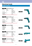
TOLEDO SCALE INTERFACE MODULE (57C428)
Address
ID BUS
OK
CPU
Watchdog
Address
Decode
Thumbwheel
Switches
0
Address
Bus
BUS
Dual Port
Arbitration
and
Control
Logic
Wait
Read
Write
1
Z80
CPU
LED
Display
Address
Address and
Control Bus
Date
8K Byte
Dual Port
Memory
16K Byte
EPROM
8K Byte
RAM
+5V
+12V
4 Channel
Counter
Timer
-12V
Serial
Interface
XMIT
RECV
DTR
2
3
4
5
20
7
BĆ1
fafadfdfdasfdsfdsdsdfdsfdsfdsfsdfdsa
afdfdsfdsfdfdsfdsfsadfda
asfdfaddfdd
!
fafadfdfdasfdsfdsdsdfdsfdsfdsfsdfdsa
afdfdsfdsfdfdsfdsfsadfda
asfdfaddfdd
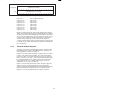
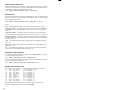
Appendix D
Toledo Scale Continuous Output
Message Format
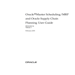
A valid message begins with a startĆofĆmessage character (ASCII STX). The
message contains three bytes of status information, six bytes of indicated weight,
and six bytes of tare weight. The message is terminated by a carriage return. A
single byte checksum follows the carriage return. The checksum is calculated by
taking the 2's complement of the sum of bits 0Ć6 of all characters preceding the
checksum character.
1
S
2
3
4
SW SW SW
T
X
5
B
C
7
8
9
10
11
Indicated Weight
X
A
6
X
(MSD)
X
X
X
(LSD)
12
13
14
15
16
Tare Weight
X
X
X
(MSD)
X
X
X
X
17
18
C
CK
R
SM
(LSD)
DĆ1
fafadfdfdasfdsfdsdsdfdsfdsfdsfsdfdsa
afdfdsfdsfdfdsfdsfsadfda
asfdfaddfdd
Appendix E
Defining Variables in the
Configuration Task
Before any application programs can be written, it is necessary to configure, or
set, the definitions of systemĆwide variables, i.e. those that must be globally
accessible to all tasks.
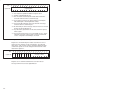
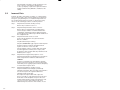
This section describes how to configure the system variables on this input
module. Refer to the figure below. Note that this procedure is only used if you are
using the Programming Executive Software Version 2.1 or earlier.
Processor Module
275 W
POWER
SUPPLY
Toledo
Scale
Interface
57428
POWER ON
P S READY
SYSTEM READY
FAULT
CODE
BLOWN FUSE
NORMAL
PROGRAM
OK
REMOTE
OK
DROP
NUMBER
1ST
2ND
120V
LINK
GND
L2
L1
FUSE
BATTERY
BACKĆUP
0
0
0
0
0
0
1
1
1
1
1
1
2
2
2
2
2
2
3
3
3
3
3
3
C1
C1
C1
C1
C1
C1
4
4
4
4
4
4
5
5
5
5
5
5
6
6
6
6
6
7
7
7
7
7
7
C2
C2
C2
C2
C2
C2
8
8
8
8
8
9
9
9
9
9
9
10
10
10
10
10
10
11
11
11
11
11
11
C3
C3
C3
C3
C3
C3
12
12
12
12
12
12
13
13
13
13
13
13
14
14
14
14
14
15
15
15
15
15
15
C4
C4
C4
C4
C4
C4
6
8
14
57491
Module
Module in a Local Rack
32 Bit Register Reference
Use the following method to reference 32 bits as a single register. 32 bit register
reference is commonly used to read indicated weight or tare weight. The
symbolic name of each register should be as meaningful as possible.
nnnnnăIODEFăSYMBOLIC_NAME![ SLOT=s, REGISTER=r]
When referenced as a long register of 32 bits, register r" is the most significant
16 bits and register r+1" is the least significant 16 bits.
EĆ1
16 Bit Register Reference
Use the following method to reference a 16 bit register. 16 bit register reference is
commonly used to reference message number and status. The symbolic name of
each register should be as meaningful as possible.
nnnnnăIODEFăSYMBOLIC_NAME%[ SLOT=s, REGISTER=r]
Bit Reference
Use the following method to reference individual inputs on the module. Single bit
reference is used to reference link status. The symbolic name of each bit should
be as meaningful as possible.
nnnnnăIODEFăSYMBOLIC_NAME@[ SLOT=s, REGISTER=r, ăBIT=b]
where:
nnnnn - BASIC statement number. This number may range from 1-32767.
SYMBOLIC_NAME! - A symbolic name chosen by the user and ending with (!).
This indicates a long integer data type and all references will access registers r
and r+1.
SYMBOLIC_NAME% - A symbolic name chosen by the user and ending with
(%). This indicates an integer data type and all references will access register r".
SYMBOLIC_NAME@ - A symbolic name chosen by the user and ending with
(@). This indicates a boolean data type and all references will access bit number
b" in the register r".
SLOT - Slot number that the module is plugged into. This number may range
from 0-15.
REGISTER - Specifies the register that is being referenced. This number may
range from 0-72.
BIT - Used with boolean data types only. Specifies the bit in the register that is
being referenced. This number may range from 0-15.
Examples of I/O Definitions
The following statement assigns the symbolic name TARE_WEIGHT! to register
71 on the module located in slot 4:
1020ăăIODEFăTARE_WEIGHT![ SLOT=4, REGISTER=71]
The following statement assigns the symbolic name LINK_STATUS@ to register
4, bit 0, on the module located in slot 7:
2050ăăIODEFăLINK_STATUS@[ SLOT=7, REGISTER=4, BIT=0]
Sample Configuration Task
The following is an example of a configuration task for the interface module:
1000
1010
1020
1030
1040
1050
1060
1070
1080
1090
IODEF
IODEF
IODEF
IODEF
IODEF
IODEF
IODEF
IODEF
IODEF
IODEF
LINK_STATUS@[
LINK_CONF%[
BAUD_RATE%[
RQST_STATUS%[
MSG_NO%[
STATUS_A%[
STATUS_B%[
STATUS_C%[
INDICATED_WT![
TARE_WEIGHT![
SLOT = 5, REGISTER = 4, BIT=0 ]
SLOT = 5, REGISTER = 20 ]
SLOT = 5, REGISTER = 21 ]
SLOT = 5, REGISTER = 64 ]
SLOT = 5, REGISTER = 65 ]
SLOT = 5, REGISTER = 66 ]
SLOT = 5, REGISTER = 67 ]
SLOT = 5, REGISTER = 68 ]
SLOT = 5, REGISTER = 69 ]
SLOT = 5, REGISTER = 71 ]
Each application task that references the symbolic names assigned to the
interface module must declare those names COMMON.
EĆ2
fafadfdfdasfdsfdsdsdfdsfdsfdsfsdfdsa
afdfdsfdsfdfdsfdsfsadfda
asfdfaddfdd
For additional information
1 Allen-Bradley Drive
Mayfield Heights, Ohio 44124 USA
Tel: (800) 241-2886 or (440) 646-3599
http://www.reliance.com/automax
Publication J-3644-2 - June 1991
Copyright © 2002 Rockwell Automation, Inc.. All rights reserved. Printed in U.S.A.