1
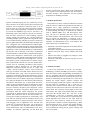
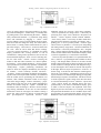
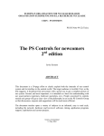
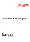
Advances in Engineering Software 30 (1999) 529–541
www.elsevier.com/locate/advengsoft
An object-oriented program shell for integrating CAD software tools
B. Bettig, J. Shah*
Design Automation Laboratory, Department of Mechanical and Aerospace Engineering, Arizona State University, Tempe, AZ, 85287-6106, USA
Received 1 June 1998; accepted 1 October 1998
Abstract
The number of CAD programs and their capabilities have risen greatly in recent times. As well, the number of Application Programmer
Interface (API) products and the number of representation standards for display, database storage and communication has also risen. These
applications, API products and representation standards are generally not compatible except through specific, individually programmed
interfaces. Incompatibility of API software products arises because of: (i) different representations for the same information, and (ii) different
ways of communicating with the API products. This article describes the derivation of a generic software architecture to overcome the second
source of incompatibility. The derivation employs the ‘‘box structure’’ (system engineering) software development methodology in a
generic, high level manner; by considering activities performed with current CAD software, but without going into the details. The objective
is to determine the types of software objects required and the types of messages that must be passed between them. The result is an
architecture in which Tool objects embodying individual software tools are plugged into a Shell object which holds the Tool’s together
as a single program, provides for interactions between Tool’s and controls when each Tool is active. In this way separately developed
software tools can be combined seamlessly into a highly graphical and interactive environment. q 1999 Elsevier Science Ltd. All rights
reserved.
Keywords: CAD/CAM software; Software architecture; Framework; Software environment
1. Introduction
The number of CAD applications (i.e. programs) as well
as their capabilities has risen greatly in recent times. These
CAD applications represent significant programming efforts
that are repeated by each CAD program developer and
researcher. These efforts are also ongoing, as the environment within which the programs run are constantly changing. Code development time is minimized by making as
much use as possible of publicly and commercially available software (usually via an Application Programmer Interface, API), but the code must still be developed to introduce
the API to the rest of the program. Also, these APIs often
change and the code must be updated. Add-on developers
limit their development expenditures by not duplicating
common functionality already available in CAD packages
but instead focus on developing new functionality. The
disadvantage of this approach is that many versions of the
add-on must be developed, one for each CAD package to
which it will be attached. Obviously standardization of data
structures, modes of communication, and types of messages
are necessary to reduce the duplication of code.
* Corresponding author. Tel.:11-602-965-6145; fax: 11-602-965-2142.
E-mail address: [email protected] (J. Shah)
A broad picture of the problem is shown in Fig. 1. We
define a software ‘‘tool’’ as the complete code necessary
and specifically pertaining to a software user performing a
specific task. All software tools making up a CAD application must, therefore, have code corresponding to each level:
‘‘User Interface’’, ‘‘Information’’ and ‘‘Core Functionality’’. Standardization proceeded at each level in the areas
shown (ovals), but integration of areas and integration of
tools was given much less consideration. Also, many duplicate standards (and specifications) exist for the same area.
For example, at the User Interface level, a modern CAD
program must have functionality for creating and retrieving
input from windows (‘‘Windowing’’ in Fig. 1) and functionality for showing geometry (‘‘Geometry Drawing’’). In
each area, CAD program developers must decide which
environments they will support and must follow the corresponding standards or specifications. For instance, a CAD
program must run under one of X-Windows, Windows NT,
Windows 95, etc. and therefore, must use data structures and
make procedure calls accordingly. To make windows
programming easier, ‘‘toolkits’’ like UIMX, LOOKS, etc.
are available, which are often object-oriented, encapsulate
the windowing behavior, and provide default functionality
for most common situations. Therefore, the programmer
does not need to go into low-level details. By choosing a
0965-9978/99/$ - see front matter q 1999 Elsevier Science Ltd. All rights reserved.
PII: S0965-997 8(99)00009-5
530
B. Bettig, J. Shah / Advances in Engineering Software 30 (1999) 529–541
Fig. 1. Elements and environments of a CAD program.
particular toolkit, however, the developer is again locked in
to using the corresponding data structures and function
calls. Moving to a different toolkit requires modification
of the code. The problem is pervasive because it is repeated
in each individual area.
Even though the integration issues in each area are different, they share the same underlying generic problems: (1)
data representations, even for the same information, are
incompatible between APIs, sometimes simply because of
different base classes, (2) different ways of communicating
with libraries, i.e. different functions or callbacks. There is
also a desire for software tools to be ‘‘pluggable’’, i.e. these
tools should either require no modifications to existing code,
or the addition of new code to integrate them into the user
interface and data model environments. In Fig. 1, tools are
shown using APIs from the preceding three levels. The tools
reside in an application shell that serves to hold the tools
together as a single program, to provide for interactions
between tools and to control when each tool is active. A
shell can also provide various degrees of insulation from
changes to APIs by itself acting as an interface to an API
(dotted lines). The shell must be compiled for one or more
platforms (e.g. NT, OS/2…) and tools must be written in
some language (e.g. Java, C11…) which largely depends
on the type of architecture and the level of insulation
provided by the shell in that architecture. The problem of
Mechanical-CAD software tool integration is very similar to
the problem of integrating Computer-Aided Software
Engineering Tools (CASE tools) except that here the integration must be much tighter to allow tools to share the same
windows (e.g. geometry viewers) and the model data in the
immediate memory.
In this big picture this article focuses on the second
problem of incompatibility given earlier: differences in
forms of communication between libraries and types of
messages passed. The focus is only on tool integration,
but this is found later to solve many API product integration
problems too, as a tool can itself act to integrate an API
product. The aim is to derive an architecture which is optimal, in terms of promoting code re-usability and ease of
integration (pluggable), and which is complete, to avoid
changes to it in the future. The architecture should define
the types of software objects required and the types of
messages that must be passed between them. In the end,
separately developed tools (or API products) should
combine seamlessly into a highly graphical and interactive
environment.
2. Literature review
For our purposes we are interested in generic architectures that integrate software tools and API products as parts
of the same application. Integration issues related to integrating a single API product into an application are brought
out by Shah et al. [1]. In particular, interfaces can be static or
B. Bettig, J. Shah / Advances in Engineering Software 30 (1999) 529–541
531
describes a framework, which, similar to the CASE framework, requires tools to implement their own user interfaces
and data interfaces. This framework also has separate
components for handling meta data.
Fig. 2. Generic requirement analysis with application as black box.
3. Problem specification
dynamic (information going one way or both ways in realtime), interfaces can be with respect to data or functions and
interfaces can be sequential or concurrent (wait or do not
wait for action to occur). The idea of providing a standardized CAD/CAM programming environment is presented
by Jayaram and Myklebust [2], however, the focus is on
determining what system support to provide (as API functions and data structures for solid modeling, equation
solving, creating user interfaces, etc.) and the problem of
combining multiple, generic application components (tools)
is not considered. Bettig and Han [3] present a much more
generic, lightweight framework which allows multiple tools
to be ‘‘plugged in’’ but is aimed at numerical analysis applications and lacks a formal derivation. (Improvements made
in the present research also benefit these numerical analysis
applications.) Abeln [4], Mink and Roller [5] and Dankwort
[6] describe work in Germany to develop a standardized
CAD architecture in which software components and applications can be integrated. A salient feature of the proposed
architectures is a data pipeline connecting software components, the product model and a knowledge base. Also, the
user interface system is implemented as a separate component, not associated with tools as in our case. Another architectural style for combining mechanical CAD software
applications is that of Jayaram et al. [7]. Their approach
implements integration through the use of ‘‘plug’’ and
‘‘socket’’ objects in which a ‘‘socket’’ class is created for
each type of software tool which will be allowed to access
the model data and a ‘‘plug’’ class is created for each CAD
program to be integrated. This approach allows the existing
applications to be integrated, but the level of integration is
restricted. In the area of software engineering, environments
for CASE tool integration are discussed by Wasserman [8]
and Thomas and Nejmeh [9]. A salient point from these
studies is that tool integration must be considered in terms
of five independent issues: platform integration, presentation (user interface) integration, data integration, control
integration, and process integration. With regards to the
presentation, data and control integration, the present
requirements are tighter than those for CASE tools because
separate tools must show data in the same window (e.g.
viewing FEA model superimposed on solid model), tools
must share the working model in immediate memory and
real-time notification is required for minor events such as
when dragging. Also of significance is the fact that each
CASE tool is comprised of three parts, just as the tools in
Fig. 1: Presentation (User Interface), Shared Repository
access (Information) and Tool Functionality (Core Functionality). In electrical engineering, van der Wolf [10]
The problem is to devise a software architecture in which
software tools for common and specialized CAD tasks are
pluggable into a single application environment. The
domain of tasks performed, and thus the scope of the tools
is solid modeling and analysis as performed by software
such as I-DEAS (SDRC [11]) and Pro-Engineer (PTC
[12]). The aim is to determine what base classes to use
and what attributes and methods these base classes must
have to support tool pluggability, to maximize code reusability and to provide for all types of information representations and manipulations in the CAD domain. The
requirements may be summarized as:
• architecture must allow integration of tools from all areas
of mechanical design;
• architecture must be platform and language independent;
• software tools must share viewer windows and model
data;
• software tools must be pluggable (no changes or additions to existing code);
• architecture must allow for real-time response of events
between tools.
4. Solution procedure
To derive the architecture, we use the ‘‘box structure’’
methodology of Hevner and Mills [13] because it is unique
from other object-oriented programming methodologies in
that it is systematic and involves a functional decomposition. The method first involves considering the system as a
black box and defining the requirements for it. This means
defining the stimuli (inputs), responses (outputs) and
processes mapping stimuli into responses. One then zooms
into the black box, expanding it into a ‘‘state box’’ by
separating state variables into one interior box, and functionality into the other interior black box. The input to the
interior black box is then the external input as well as the
internal state. The output of the internal black box sets the
state and is the external output. The ‘‘state box’’ is then
expanded into a ‘‘clear box’’ in which the interior black
box is divided into several black boxes implementing the
system algorithm in the form of a flow chart. Each new
black box is then recursively visited in the same way.
This procedure is similar to systems engineering (e.g. Blanchard and Fabrycky [14]). To make the problem manageable, we apply the ‘‘box structure’’ methodology at a high
level of abstraction, looking only at generic concepts with
low level of detail.
532
B. Bettig, J. Shah / Advances in Engineering Software 30 (1999) 529–541
Table 1
Interaction forms
Table 3
Types of processes arising from Table 1 stimuli and Table 2 forms of
display
Forms of information display
Processes
1. Textual
2. Table/list
3. Rendering (showing the physical artifact)
4. Graph (having ordinates)
5. Diagram (showing relationships using edges between icons)
6. Ancillary control (e.g. menu, toolbox, dialog box)
The stimulus and response of the overall system are from/
to the user and from/to a product database as shown in Fig.
2. The stimulus from the user is the actions as performed
through a keyboard, mouse or other input device. The
response to the user is the display of changes in the information maintained by the system. The form in which the information is displayed and the user’s specification of their
intended action (e.g. through the selection of a particular
tool from a toolbox window) provide a context in which
keyboard and mouse events can be interpreted. The combinations of forms of information display and user actions
provide all the cases for which processes are required to
map stimulus to response.
The forms of information display (Table 1) were derived
by compiling and categorizing a list of all types of windows
and window components presented to the user in I-DEAS
Master Series 5 (SDRC [11]). The first form is textual. An
example of this is the prompt window into which commands
can be typed as a string of characters. The second form of
display, tables/lists occurs with most of the manager dialog
boxes. Here a row of a table represents an instance of an
information entity. A rendering is used to visualize physical
geometry. This is the main viewing window. The geometry
may also be annotated with text. Graphs may be created in
the simulation application to show the results of an analysis.
A graph is distinguished by the fact that it has ordinates, and
the position of points in space indicates a value associated
Table 2
Actions using a CAD program
Actions using a CAD program
A. Create entity
B. Delete entity
C. Modify entity attribute/add attribute
D. Refine (create a set of entities to further describe an existing entity)
E. Store/retrieve (including transmit/receive)
F. View/set viewing parameters
G. Pick
H. Search
I. Study/clarify-analysis results simply displayed
J. Evaluate-analysis results kept
K. Enforce consistency
L. Present-output only
M. View/set parameters for doing action
N. View activity status
O. View/set application resource or parameter
P. Perform combination of above actions
1. Create entity by typing command (A-1)
2. Create entity by dragging point device(A-3)
3. Create entity by pressing button (A-6)
4. Delete entity by typing command (B-1)
5. Delete selected entity (B-2,3,5)
6. Modify by typing command (C-1)
7. Modify by dragging (C-3,6)
8. Modify by re-typing information (C-6)
9. Modify by pressing button (C-6)
10. Refine by typing command (D-1)
11. Refine by pressing button (D-6)
12. Store/retrieve/transmit by typing command (E-1)
13. Store/retrieve/transmit by pressing button (E-6)
14. Change view type/parameters by typing a command (F-1)
15. Change view parameters by dragging in view (F-3,4,5)
16. Change view type/parameters by pressing button or moving slider
(F-6)
17. Change window/control preferences in dialog box (F-6)
18. Pick by highlighting row (G-2)
19. Pick by selecting with pointing device (G-3,5)
20. Search by typing command (H-1)
21. Specific search by pressing button (H-6)
22. Study/clarify by typing command (I-1)
23. Study/clarify by pointing with a mouse (I-3)
24. Study/clarify by pressing button (I-6)
25. Evaluate by typing command (J-1)
26. Evaluate by pressing button (I-6)
27. Enforce consistency by typing command (K-1)
28. Enforce consistency by pressing button (K-6)
29. Present output by typing command (L-1)
30. Present output by pressing button (L-6)
31. View/set parameters for doing action-by typing command (M-1)
32. View/set parameters for doing action-using dialogue box (M-1,6)
33. Select input mode/tool by typing command (M-6)
34. Select input mode/tool by selecting from menu/pressing button
(M-6)
35. View activity status by typing command (N-1)
36. View activity status by pressing button (N-6)
37. View/set application resource or parameter using dialog box (O-1,6)
38. Perform combination of above actions by typing command (P-1)
39. Perform combination of above actions by pressing button (P-6)
with the point. A diagram is different from a graph in that
the information is derived from edges drawn between icons
and not necessarily from the position of the icon. An example of a diagram is the Construction History diagram. Other
types of windows do not fall easily into these categories (all
of which have equivalents on paper). The toolbox, which
has buttons to select a tool, is such an example. The menu
and dialog boxes are another. These are labeled as ancillary
controls in Table 1.
The list of user actions (Table 2) was generated by
compiling and categorizing the menu and dialog box
commands found in I-DEAS Master Series 5. One of the
largest categories, by number of commands, is ‘‘create
entity’’ as there is a separate command to create each type
of entity. Entities are created by dragging the mouse on the
B. Bettig, J. Shah / Advances in Engineering Software 30 (1999) 529–541
533
Fig. 3. Expansion: create state.
screen, by typing values in the prompt window or by entering values in a dialog box. ‘‘Delete entity’’ is normally done
by picking entities to be deleted using the mouse. ‘‘Modify
entity attribute/add attribute’’ is performed using dialog
boxes and sometimes by dragging. A ‘‘refine’’ action
involves adding a new level of information about an entity.
This action does not change the entity, but refines what is
known about it. Creating a finite element mesh of a part is
put in this category. ‘‘Store/retrieve’’ actions are those from
the ‘‘File’’ menu as well as those that involve catalogs.
‘‘View/set viewing parameters’’ is commands for setting
display parameters like viewing direction as well as
commands for setting control preferences such as how the
menus should be displayed. ‘‘Pick’’ involves selecting entities for some action. ‘‘Search’’ involves traversing the
model to find and collect instances of a desired pattern.
For instance, ‘‘Clean unused parameters’’ involves searching for parameters not used in any equations or dimensions.
‘‘Study/clarify’’ requires performing calculations, the
results of which are displayed immediately and not kept;
for instance, ‘‘Check Geometry—Surface Curvature’’.
‘‘Evaluate’’ requires performing calculations and maintaining the results. This requires that consistency be maintained
with the model used in performing the calculations. For
instance, finite element calculation results are no longer
valid if the design changes. ‘Enforce consistency’’ propagates changes from one part of the model information to
another; for instance using the ‘‘Update’’ command after
a dimension value was changed. ‘‘Present’’ involves outputting existing information to the user in some formatted
manner that cannot be read again; for instance creating a
picture file. These actions act directly on model data and
have pre-computer-era equivalents, however some
additional actions are necessary when using computers.
‘‘View/set parameters for doing actions’’ is necessary for
specifying how input events should be interpreted; for
instance, ‘‘Orient—Options—Rotate Default Method’’.
‘‘View activity status’’ is necessary for tasks which take a
long time for the computer to perform; for example ‘‘File—
plotting jobs’’ to see if a job has printed. ‘‘View/set application resource or parameter’’ is necessary for doing things
like setting memory usage limits. ‘‘Perform combination of
above actions’’ is necessary for things like ‘‘File—Program
Files’’, which is similar to running a macro. The combinations
of these actions and the forms of information display (Table
3) must be supported by a CAD software architecture.
The next step of the procedure is to expand the black box
into a ‘‘state box’’ by separating the state variables as shown
in Fig. 3. The design model is chosen as one state variable
and the current input model is chosen as another. The choice
of state variables is a design decision. The diagram in Fig. 3
is also rearranged to have stimuli on the left and responses
on the right. The next step is an expansion to ‘‘clear box’’ as
shown in Fig. 4. We deviate here from the normal application of the ‘‘box structure’’ methodology and use arrows to
represent the flow of control through message passing rather
than showing a sequence of instructions. The choice of how
to do the expansion is again a design issue. Here the choice
is to divide functionality between ‘‘Interface’’ objects and
‘‘Tool’’ objects. In this way Interface objects can correspond directly to the forms of information display given
in Table 1 and Tool objects can implement each of the
high level processes from Table 3. For example, for setting
the input mode the Interface can be a ToolBox object with a
grid of buttons for each input mode and the Tool can be a
ModeSelect Tool. This is shown as Scenario 1 in Fig. 5. The
Fig. 4. Expansion: create procedure.
534
B. Bettig, J. Shah / Advances in Engineering Software 30 (1999) 529–541
Fig. 5. Scenario 1: setting input mode.
communication which is required involves: (1) detecting the
mouse button press over the button, (2) passing this to the
ModeSelect Tool as a button pressed event, (3) setting the
Input Mode state variable, (4) telling the ToolBox object to
highlight the button, and (5) changing the user output to
show the button as highlighted. Another scenario, creating
some kind of geometrical entity through a three-dimensional (3D) viewer is shown in Fig. 6. In this the communication involves: (1) mouse events passed to viewer, (2)
mouse events translated into 3D positions (on a drawing
plane) and passed to the CreateEntity Tool, (3) new entity
passed into the model state, (4) rubber-banding commands
sent to 3D viewer, and (5) updated geometry displayed. By
considering the communication for each type of process in
the same manner, we compile and categorize the communication events in order to determine what attributes and
methods should be part of the base classes. For Interface
objects, communication to and from the user is obviously
controlled by windowing standards discussed in Section 1
and involves standard GUI events. Communication from the
Interface object to the Tool and from the Tool to the
Interface object is given in Tables 4 and 5. The events are
categorized into small lists of generic messages that are later
implemented as methods in the base classes. Note that
messages passed from the Tools to the Interfaces are specific
to the different types of Interfaces derived from items in Table
1. Types of messages passed from Tool objects to the Shell
regarding state variable changes are given in Table 6.
Another scenario that must be considered is multiple,
integrated tools. We make the assumption that many Interface objects can exist at the same time, but that only one,
corresponding to a single Tool object, is used at a time.
Many Tools can exist at the same time being either:
1. independent of other Tools;
2. reliant on other Tools or;
3. affected by other Tools.
The first case requires no further analysis. The second
case implies the use of functionality from other Tools; that
is, using other Tools as building blocks. In this case, the
messaging may be both ways (e.g. calling methods directly
and getting callbacks). Due to the wide variety of Tools
there does not seem to be a good way of categorizing
inter-Tool messages into a set of generic messages. InterTool messaging should, therefore, be addressed in a completely flexible fashion in the implementation. For the third
case, a Tool may be affected by other Tools only in so far
as that data maintained by the Tool is changed by other
Tools so that it becomes inconsistent. For data internal to
the Tool this cannot happen if good programming practice is
Fig. 6. Scenario 2: creating new geometry through viewer.
B. Bettig, J. Shah / Advances in Engineering Software 30 (1999) 529–541
Table 4
Types of messages passed from interface to tool (with reference to Table 3)
535
Table 6
Types of messages passed from tool to shell to modify state (and shell to
tool for event notification)
Messages
Messages
1. Text string (1,4,6,10,12,14,20,22,25,27,29,31,33,35,38)
2. Standard GUI events (button pressed, key pressed, mouse moved,
etc.) (2,3,5,7,9,11,13,15,16,18,19,21,23,24,26,28,30,32,34,36,37,39)
3. ‘‘Apply/updated/OK/finished’’ event after data was entered
(3,5,8,9,11,13,16,17,21,24,26,28,30,32,34,36,37,39)
4. 3D GUI events (2,5,7,15,19,23)
5. Execute button press command
(3,9,11,13,16,21,24,26,28,30,34,36,39)
Table 5
Types of messages passed from tool to interface (with reference to Table 3)
Message/Transaction
1. Print text string (all)
2. ‘‘Rubber-banding’’ (2,7,8,19,23)
3. Temporarily display 2D/3D text, marker, line, etc.
(18,19,22,23,24,29,30)
4. Update/redraw
(1,2,3,4,5,6,7,8,9,10,11,12,13,14,15,16,18,19,22,23,24,25,26,27,28)
5. Change dialog box component setting
(14,15,16,17,31,32,33,34,37)
6. Change type of view (14,16)
7. Change view parameter (14,15,16)
8. Change control arrangement (17)
employed in the implementation. The only data external to
the Tools is the model and input mode, and this CAN
become inconsistent as shown by the example in Fig. 7. In
this example, the model geometry changed by one Tool
(ModifyShape) becomes inconsistent with respect to
another tool (ConstraintMgr) which is used to position the
geometry in accordance with the dimensional constraints.
This problem can be resolved without resorting to inter-Tool
communication by broadcasting changes to the model or
input mode (Table 6) to each Tool. These broadcasts then
make up the messages going from the Shell to the Tools.
1. Add entity to model
(1,2,3,10,11,12,13,25,26,27,28)
2. Remove entity from model (4,5,27,28)
3. Change model entity attribute
(1,2,3,4,5,6,7,8,9,10,11,12,13,18,19,25,26,27,28)
4. Set input mode (33,34)
5. Implementation
The implementation is almost a direct mapping of the
architecture, described earlier, into program classes: ‘‘Interface’’ to Control, ‘‘Tool’’ to Tool and ‘‘Shell’’ to
CADshell. The Control objects must send the messages
of Table 4 to Tool objects and must have methods available for handling Table 5 messages. Tool objects must
have methods available for handling Table 4 messages
and must send Table 5 messages to Control objects.
The Tool objects also send Table 6 messages to the
CADshell object, which must therefore have appropriate
methods to receive the messages. The CADshell object
broadcasts Table 6 messages to Tool objects, which must
have methods to handle Table 6 messages.
The Control classes are closely matched with the typical types of windows available in the Window toolkits
described in Section 2, but offer slightly more specialization
as with Visual BASIC controls. The types of Control
classes include, for example, windows for text input,
number input, sliders, checkboxes and 3D geometry viewers. The primary difference between these Control
classes and those from the typically availabe are two: (1)
as the Control objects ‘‘know about’’ the application
environment, fewer parameters need to be passed to create
Dialog boxes, Message Boxes, etc. making programming
easier, and (2) Control objects have references to associated
Fig. 7. Scenario 3: modifying design geometry and maintaining consistency.
536
B. Bettig, J. Shah / Advances in Engineering Software 30 (1999) 529–541
Fig. 8. The Control base class.
Tool objects so that event notification is automatic and
does not require a callback mechanism. Control objects
simply call methods on Tool objects. Programming is also
simplified because Control objects take references to the
variables they control, so that transferring of values to
controlled variables is automatic. The methods provided
in the base Control class are shown in the (abbreviated)
C11 class definition given in Fig. 8. Note that Table 5
methods are only available in sub-classes as applicable.
Core functionality for each new Tool is coded in classes
derived from the Tool base class. Another class is then
derived from this one in order to add presentation (User
Interface) functionality by also implementing/inheriting
one of the three interfaces derived from the ToolPresentationInterface: ViewerInput, DialogBoxInput or CommandInput. This approach is beneficial
because it allows the core functionality to be accessed
with different types of user interfaces. The abbreviated
class declarations are shown in Figs. 9 and 10. AddCallback(), PerformNotify() and ToolEvent() are used
to implement inter-Tool messaging. AddCallback() adds
the Tool requesting the callback to the callbackTools
list corresponding to the named event. PerformNotify()
sends the event to the ToolEvent() function of each
Tool listed. The inter-Tool event notification mechanism
is not used as much as the broadcast mechanism as it creates
Tool interdependence.
A ToolPresentationInterface may be one of
the three types: ViewerInput, DialogBoxInput or
CommandInput. The ViewerInput interface allows
for passing of messages from a Viewer Control to a
Tool in order to implement actions that are performed
through a viewer such as those that involve dragging the
mouse. The DialogBoxInput interface is meant for
Tools which pop up a dialog box when they are selected.
The CommandInput interface is used for Tools that
simply perform a command immediately after they were
selected.
The CADshell class has member methods and attributes
as shown in Fig. 11. It holds environment variables, the list
of Tools, the model and the main application windows.
The application name, resource directory and preferences
Fig. 9. The Tool base class.
B. Bettig, J. Shah / Advances in Engineering Software 30 (1999) 529–541
537
Fig. 10. Tool presentation interfaces.
file are set and retrieved in the constructor and corresponding Get/Set functions. The application name is used in
message boxes, the main window and in files to identify the
source application. The resource directory is needed by
Tools because it contains menu definitions, icons and
other application specific resource data. The preferences
file is used to read and save user preferences for each
Tool upon program startup and shutdown. A list of
Tools registered using the PlugInTool() function is
maintained as toolList and may be retrieved as a list
(GetTools()) or individually by name GetTool()). The
input mode is implemented simply as a Tool pointer,
currentTool, which is set using SelectTool(). The
currentTool receives all mouse and keyboard events
from the viewer. A design or analysis model is maintained
in an Entity tree structure held in model and is retrieved
using GetModel(). The Entity class is not discussed in
this article. Entity’s may be added or removed from the
model using AddEntity() and RemoveEntity(). The
functions NewEntityNotify(), ChangedEntityNotify() and DeleteEntityNotify() are called by
Tools to notify the shell about model changes. (Having
Tools manually notify about changes to high level
branches of the model was found to be more efficient than
automated methods reporting all changes to individual
entities). The lists of changed Entity’s are accumulated in newEntities, changedEntities and
deletedEntities. These lists are then broadcast to
plugged in Tools and purged in between GUI events.
CADshell also has as member attributes instances of
Controls: mainWindow, viewer, menu, toolbox,
commandbar and messagebar. In the present implementation, these are not associated with any Tools except
viewer which is associated with currentTool. The
Control objects can each be obtained, and some can be
set, with corresponding function calls. The static variable
the_shell is used to hold a pointer to the one and only
CADshell instance. It is set in the CADshell constructor
and can be obtained using the static member function
GetShell().
6. An example solid model geometry editing program
An application is created by combining both the general
Tools and Tools that are specific to the problem at hand.
For example, a program to edit solid models requires functionality to load the model from a file, functionality to select
and move entities and functionality to maintain geometrical
constraints. From the user’s perspective, each action
involves selecting a tool and then using it. In opening the
file, the user selects a Tool associated with ‘‘File—Open’’
and a dialog box appears. Entering the name of the file and
pressing OK, makes the action proceed, and if there are no
538
B. Bettig, J. Shah / Advances in Engineering Software 30 (1999) 529–541
Fig. 11. The CADshell class.
errors, the user is finished with that Tool. Fig. 12(a) shows
an application with a part that was loaded. Here the menu is
at the top, a toolbox is on the left, a status bar is at the
bottom and a 3D viewer is in the middle. The view angle,
zoom and centering are controlled by the scrollbars
surrounding the viewer. The next Tool selected is the
PickTool, which is used to select entities, move them
and resize them. In Fig. 12(b), the entities of a hole were
highlighted. The entities are highlighed and a bounding box
drawn around them. The selected entities can be dragged as
a whole or the handles on the bounding box can be grabbed
to resize the hole. In Fig. 12(c), the hole was resized and
moved. Selecting the drawing tools allows one to sketch a
profile as shown in Fig. 12(d).
The main program is very straightforward and requires
very few lines, as shown in Fig. 13. The main program
simply involves creating an instance of a CADshell
object, ‘‘plugging in’’ new instances of Tool objects and
calling the CADshell Run() function to start the event
processing loop. The shell PlugInTool() function is
called for each Tool to be registered with the CADshell.
These Tools are persistent until the program terminates.
The first Tool, of type FileToolModule, is simply a
collection of a set of Tools necessary for saving and loading
files, starting a new file and exiting the program. The code
for FileToolModule is given in Fig. 14. The STEPmodule object introduces topological, geometrical and
constraint entity classes from STEP AP203 (ISO [15]) and
a proposed constraints schema. The ConstraintsModule introduces code to enforce geometric constraints in
the model.
7. Discussion
The procedure employed to create the software architecture involved categorizing the forms of information display
normally used in mechanical CAD software and categorizing actions performed using the software. The system engineering, ‘‘box structure’’ software design methodology was
then used to separate the software into generic functional
elements: interface, tool and shell. The combinations of
forms of information display and actions were then used
to generalize the types of messages required to be passed
B. Bettig, J. Shah / Advances in Engineering Software 30 (1999) 529–541
539
Fig. 12. A program using the present architecture (a) reading in a STEP file, (b) selecting the hole, (c) moving and enlarging the hole, and (d) sketching a
profile.
Fig. 13. Main program for example.
540
B. Bettig, J. Shah / Advances in Engineering Software 30 (1999) 529–541
Fig. 14. The FileToolModule class.
between the interface, tool and shell elements. The integration of multiple tools was also considered. From the analysis, base Control (interface), Tool and CADshell
classes were implemented. These were demonstrated with
an example.
The process used in designing the architecture was
useful as by performing the analysis in terms of individual generic tools, the goal of pluggability was
achieved. By separating the functionality into interface,
tool and shell components the goal of re-usability is
thought to be achieved as the architecture is minimal,
and hence should be easy to learn, yet maintains the
separation of semantic, tool specific functionality and
generic, user interface functionality so that individual
user interface components can be re-used. The integration of multiple tools is also considered, so that some
tools can be used as building blocks for others. The
categorizing of forms of information display and types
of user actions was useful in determining the types of
interfaces and tools required and the types of messages
that had to be passed. Though there may have been
omissions in generating individual lists, the process of
multiple serial generalizations (from the user actions list
to the action/display form combinations list to the types
of messages) should cancel the effect of most
omissions.
Although it was very useful to apply the ‘‘box structure’’
design methodology in high level generic terms, some
limitations of the representation were noticeable. One
problem was in representing the input to output process
implementation algorithm as a sequential series of black
boxes when we wanted messages to be passed back to the
same object. The solution to this was to make the inside of
the box into a collaboration diagram (Fowler [16]). This
allowed a representation of message passing in which the
message sequence could be extracted from the diagram.
Another problem was in representing the passing of
messages to and from the container object. In our figure
we chose to represent this using arrows to and from the
state variables. This seems to have worked satisfactorily
but the problem may also be avoidable by using the text
representation of ‘‘box structures’’ (Hevner and Mills [13]).
Alternative architectures which were considered are as
follows:
• having a single Tool base class without the presentation
level interfaces. This was not used because it does not
allow for developing, in a single Tool class, different
user-interfaces for the same core functionality. It also
does not enforce a clear distinction between core functionality and presentation code;
• directly sub-typing InputTool, CommandTool and
DialogTool classes from the Tool class. This
makes clear which methods apply for which type of
presentation, but does not allow the presentation components to be changed;
• having a Tool object to be made up of Presentation,
Functional and Data Interface Tool Fragments. This
was not used because it adds another layer to the architecture, thus increasing its complexity. Inter-fragment
communication would also be a problem;
• having Presentation, Functional and Data Interface Tool
Fragments reside directly in the shell object. This was not
used because of the same problem of coordinating
between Tool Fragments.
The architecture presented here also answers the
problems associated with integrating API products, such
as solid modeling and numerical analysis. The main
problems were: (1) setting and retrieving information, (2)
causing actions to occur when required, and (3) maintaining
consistency of data in each tool. These are answered by the
respective mechanisms: (1) a centralized model maintained
by the CADshell object, (2) Tools registered with
CADshell object can be selected/activated by the user,
dialog Controls can be created by the Tool itself and
event messages passed from other Tools can initiate
actions, and (3) model change event broadcasts can be
used to maintain data consistency. With these mechanisms,
these kinds of tools are pluggable and much more independent than otherwise possible.
B. Bettig, J. Shah / Advances in Engineering Software 30 (1999) 529–541
8. Conclusions
An object-oriented software architecture for CAD
applications was designed using the ‘‘box structure’’
methodology. The architecture greatly simplifies the
integration of code by providing a generic framework
within which tools can be combined. To integrate new
functionality, it is only necessary to ‘‘plug it in’’ using
a single function call in the main program. For removing functionality it is simply a matter of not plugging it
in. There is no need to add or remove ‘‘hooks’’ in
existing code. If a format like this can be standardized,
then it would be possible to exchange object code tools
easily between CAD vendors and between researchers.
Code re-use is promoted as new code is easy to add,
can come with its own user interface which is automatically coordinated with other user interfaces, it is automatically integrated with respect to model data and
messages can pass to and from it while treating it as
a black box.
Acknowledgements
The authors are grateful for discussions with Prof. Collofello, Prof. Lindquist and (especially) Kevin Gary from the
Software Engineering group at Arizona State University.
NSF support from grant DMI-9522971 is also greatly
appreciated.
References
[1] Shah J, Dedhia H, Pherwani V, Solkhan S. Dynamic interfacing of
applications to geometric modeling services via modeler neutral
protocol. Computer-Aided Design 1997;29(12):811–824.
541
[2] Jayaram S, Myklebust A. Device-independent programming environments for CAD/CAM software creation. Computer-Aided Design
1993;25(2):94–105.
[3] Bettig B, Han R. An object-oriented framework for interactive numerical analysis in a graphical user interface environment. International
Journal for Numerical Methods in Engineering 1996;39:2945–2971.
[4] Abeln O. The CAD-reference-model—an architectural approach to
future CAD—systems. In: Roller D, Brunet P, editors. CAD systems
development—tools and methods, Berlin: Springer, 1997, pp. 3–19.
[5] Mink U, Roller D. New ECAD system technology. In: Roller D,
Brunet P, editors. CAD systems development—tools and methods,
Berlin: Springer, 1997, pp. 41–54.
[6] Dankwort C. Cax systems architecture of the future. In: Roller D,
Brunet P, editors. CAD systems development—tools and methods,
Berlin: Springer, 1997, pp. 20–31.
[7] Jayaram U, Jayaram S, Tilton D, Seaney K. An Open architecture
framework for the integration of virtual prototyping software tools.
Proc. 1997 ASME Design Engineering Technical Conferences. Sacramento, CA, 1997.
[8] Wasserman A. Tool integration in software engineering environments, software engineering environments. Int. Workshop on
Environments, Chinon, France, 1989. Berlin: Springer Verlag,
1989.
[9] Thomas I, Nejmeh B. Definitions of tool integration for environments.
IEEE Software 1992;00:29–35.
[10] van der Wolf P. CAD frameworks, principles and architecture.
Boston: Kluwer, 1994.
[11] SDRC, I-DEAS Master Series 5 User Manuals (In on-line help),
Structural Dynamics Research Corp., Milford, OH, 1997.
[12] PTC, Pro/ENGINEER Release 20 Pro/HELP (on-line user manual),
Parametric Technology Corporation, Waltham, MA, 1998.
[13] Hevner A, Mills H. Object-oriented design with box structures. In:
Rice J, DeMillo R, editors. Studies in computer science, New York:
Plenum Press, 1994, pp. 191–211.
[14] Blanchard B, Fabrycky W. Systems engineering and analysis. 3.
Upper Saddle River, NJ: Prentice Hall, 1998.
[15] ISO, Industrial automation systems and integration—Product data
representation and exchange (STEP) ISO 10303 (TC184/SC4), International Organization for Standardization, 1997.
[16] Fowler M. UML distilled: applying the standard object modeling
language. Reading, MA: Addison Wesley Longman, 1997.