1
• HMCI 125F-EH
MOVABLE TYPE AIR CONDITIONER
WITH OZONE-FRIENDLY R410A REFRIGERANT
USER’S MANUAL
CAUTION:
PLEASE READ CAREFULLY THIS MANUAL BEFORE OPERATING YOUR NEW AIR CONDITIONER.
-1-
TERMAL S.R.L. Via della Salute, 14 -- 40132 -- Bologna -- ITALY
EN
IT
EUROPEAN REGULATIONS CONFORMITY FOR THE MODELS:
Unit Model:
HMCI 125 F-EH
CE
All the products are in conformity with the following European provision:
- Low Voltage Directive 73/23/EEC
- Low Voltage Directive 2006/95/EC
- Electromagnetic CompatibilitY 89/336/EEC
- Electromagnetic CompatibilitY 2004/108/EC
ROHS
The products are fulfilled with the requirements in the directive 2002/95/EEC of the
European parliament and of the council on the Restriction of the use of Certain Haz.
ardous Substances in Electrical and Electronic Equipment (EU RoHS Directive)
WEEE
In accordance with the directive 2002/96/CE of the European parliament,
herewith we inform the consumer about the disposal requirements of the
electrical and electronic products.
DISPOSAL REQUIREMENTS:
Your air conditioning product is marked with this symbol. This means that electrical and electronic products
shall not be mixed with unsorted household waste.
Do not try to dismantle the system yourself: the dismantling of the air conditioning system, treatment of
the refrigerant, of oil and of other part must be done
by a qualified installer in accordance with relevant
local and national legislation. Air conditioners must be
treated at a specialized treatment facility for re-use, recycling and recovery.
By ensuring this product is disposed of correctly, you will help to prevent
potential negative consequences for the environment and human health.
Please contact the installer or local authority for more information. Battery
must be removed from the remote controller and disposed of separately in
accordance with relevant local and national legislation.
-2-
Table of Contents
PRODUCT FEATURES......................................................................................................... 4
SAFETY PRECAUTIONS..................................................................................................... 5
OPERATING CONDITIONS & ACCESSORIES................................................................... 8
EXTERNAL APPEARANCE OF THE UNIT.......................................................................... 9
CONTROL PANEL & LED DISPLAY.................................................................................. 10
OPERATING INSTRUCTIONS........................................................................................... 11
IR REMOTE CONTROL...................................................................................................... 13
INSTALLATION................................................................................................................... 27
MAINTENANCE.................................................................................................................. 33
TROUBLESHOOTING........................................................................................................ 35
-3-
PRODUCT FEATURES
- No special installatio work is required. You only have to put the end of the exhaust hot air
duct to a nearby window.
- You can modify all operating parameters by pressing the high-sensitive buttons on the front
panel of the air conditioner.
- The digital display on the front panel shows useful information about the air conditioner’s
operation.
- It is very easy to move the air conditioner from one room to another, thanks to the casters
mounted at the bottom of the Unit.
- According to the User’s needs, also a permanent installation mode is available.
- It is possible to program the air conditioner’s start and stop by TIMER function.
- The condensate is automatically evaporated and conveyed outside through the flexible pipe
in Cooling mode.
- This air conditioner is equipped with a high-reliability and low noise level compressor.
- The electronics inside the air conditioner provide several protection functions able to stop
the Unit automatically in case of abnormalities during operation.
!
Warning
“Heating” function is carried out by an electric resistance
of 1900 W.
In this operating mode, the compressor is off.
PAY ATTENTION TO ENERGY CONSUMPTION!
-4-
SAFETY PRECAUTIONS
• To take best advantage from your new air conditioner and for correct operation, please
read carefully this Manual.
• Hazard and safety levels are shown via warning and alert signs as listed below.
!
!
Warning
May result in life-threatening danger or severe injury if
operated incorrectly.
Caution
May result in injury or damages to property and assets if
operated incorrectly.
• In this Manual, the meaning of each symbol is as follows:
This symbol indicates prohibitive.
!
This symbol indicates please follow the instructions.
This symbol indicates to disconnect the power plug.
!
!
!
!
Caution
• When moving the Unit,
make sure to turn off the
power as water spilled
from the water tank may
lead to hazards such as
electroshock or fire.
• If you choose the
continuous
drainage
option (see further on)
please check the drain
hose is properly placed
to avoid any leakage.
• Before cleaning the
unit, turn it off and
disconnect the power
plug as the fan rotation
may result in safety
hazard.
-5-
!
!
!
• Locate the Unit on
a horizontally-leveled
surface to avoid water
leakage or hazard such
as electroshock or fire.
• If the room temperature
falls below 0°C, the
drain hose may freeze;
this may result in water
leakage and damages
to the furniture.
• In case of extended
idle, please remove the
power plug from the
power outlet to prevent
electroshock or fire.
SAFETY PRECAUTIONS
!
Caution
• Never block the
blowout vent or intake
vent with clothing or
rags.
• The air conditioner
is designed
for indoor use;
exposure to direct
sunlight or rain may
cause electroshock
or fire.
• Do not place the Unit
near fuel or combustible
gas thus preventing fire
hazard or inflammable
gas leakage.
• Do not expose
the Unit to moisture
as this may lead to
electroshock or fire.
• Do not spurt water
on the Unit as this may
cause electroshock.
Never touch the air
conditioner with wet
hands.
• Never install the Unit
in narrow spaces.
• Do not extend or
shorten the power
cord.
• Never attempt to sit
or ride on the Unit as
this may lead to injury
through accidental fall.
-6-
SAFETY PRECAUTIONS
!
!
Warning
• Never turn on and
off the air conditioner
by plugging and
unplugging the power
tap from the wall
receptacle.
• Keep the power plug
clean from dust and
make sure it is securely inserted into the wall
receptacle.
!
• Do not extend or
overload the power
cord to avoid hazards
of electroshock, fire or
overheating.
!
!
• Make sure the power
value on the wall
receptacle is correct
(220V).
If not so, this
may result in fire,
electroshock or severe
damage to the Unit.
• Avoid the power cord
to get overheated,
as this may result in
hazard of electroshock
or fire.
• Do not insert any
sharp objects into the
intake or blowout vent
as the fan rotating at
high speed may cause
injuries to people and
short circuiting on the
Unit.
• If the air conditioner
should emit any
burning smells,
immediately stop it;
disconnect the power
plug from the wall
receptacle and contact
your dealer or the
nearest Authorized
Service Center.
• Keep the Unit
away from heating
appliances as this
may cause melting
or combustion of the
plastic shield.
-7-
OPERATING CONDITIONS & ACCESSORIES
In order to obtain the best performance of the appliance, it is recommended its use according to the following
conditions:
ROOM TEMPERATURE
OPERATION MODE
COOLING
17°C ~ 35°C
DRY
13°C ~ 35°C
HEATING
5°C ~ 30°C
Note: Performance may be reduced outside of these operating temperatures.
Energy Save
Use the Unit in the recommended room size.
Locate the Unit where furniture cannot obstruct the air flow.
Keep blinds/curtains closed during the sunniest part of the day.
Keep the filters clean.
Keep doors and windows closed to keep cool air in and warm air out (cooling mode)
or keep warm air in and cool air out (heating mode).
Accessories
COMPONENT
PART’S NAME
QUANTITY
Exhaust hose with adapter B
1 set
Window Slider Kit & screw
1 pc
Foam seal
3 pc
IR Remote Control & Batteries
1 set
FAN
HIGH
MED
LOW
TIMER ON
TIMER OFF
SET TEMPERATURE( C)
AUTO
COOL
DRY
HEAT
TEMP
ECONOMY
ON/OFF FAN SPEED
RESET LOCK
FOLLOW
LED
ME
DISPLAY TURBO
ION
SWING
MODE
Drain Hose (For continuous drainage)
Please check all the accessories are included in the package and please refer to the installation instructions for
their usage.
-8-
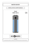
EXTERNAL APPEARANCE OF THE UNIT
NAMES OF PARTS
Front view
2
1
4
1
Operation Panel
2
Horizontal Louver Blade
(Lift it up during operation)
3
Air intake (air filter inside)
4
Carrying Handle (both sides)
3
NOTE: The illustrations are for
explanation purposes only.
The actual shape of the machine
you purchased may be slightly
different.
Fig.1
Rear view
5
6
9
7
10
8
5
Air intake
6
Power cord outlet
7
Drain Outlet A (Used on
Dehumidifying operation)
8
Drain Outlet B (Used on
Heating operation)
9
Air Outlet
10
Air intake (Air filter inside)
Fig.2
-9-
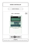
CONTROL PANEL & LED DISPLAY
OPERATION PANEL OF THE AIR CONDITIONER
Before you begin, thoroughly familiarize yourself with the Control Panel, the Remote Control and all their
functions, then follow the symbol for the functions you desire.
The Unit can be controlled by the Control Panel alone or with the IR Remote Control.
CONTROL PANEL & LED DISPLAY
NOTE: The following illustration is for explanation purposes only. The actual shape of the Control
Panel of the Unit may be slightly different. But the functions are the same.
auto
Turbo
ON
OFF
MODE
+
-
TIMER
SWING
ECONOMY
TURBO/FAN
Fig.3
POWER
Remote signal receiver
INDICATOR LIGHTS OF DISPLAY WINDOW
ON
OFF
auto
Timer on indicator
(Programmed automatic start)
Fan speed indicator
Low
Timer off indicator
(Programmed automatic stop)
Med
Hi
Auto: illuminates gradually.
Auto operation indicator
Cooling operation indicator
Economy operation
(Energy Save)
Dry operation indicator
Fan operation indicator
Turbo
Heating operation indicator
Turbo display
Clean Air operation (optional)
Follow me indicator
- 10 -
OPERATING INSTRUCTIONS
Display
Shows the set temperature in “°C” or “°F” and the Error
Codes.
Error Codes:
- Room temperature sensor error
Unplug the Unit and plug it back. If error repeats,
please call the Authorized Technical Service.
3 TURBO/FAN button
Press the TURBO/FAN button to select the desired
fan speed:
LOW
Button functions on Control Panel
FAN
TIMER button
Used to select the Air Conditioner’s programmed
automatic start AUTO ON or automatic stop
AUTO OFF. After pressing this button, press
+ / - buttons for selecting the desired time interval.
5
SWING button
Allows the horizontal louver blades to oscillate
forward and backward to the desired position.
Each press will change the swing angle for 6°.
If you keep pressing the button without releasing
it for more than 2 seconds, the louver blades would
oscillate forward and backwards automatically.
6
ECONOMY button
If you press this button, the
indicator will
be displayed and the selected temperature will
increase (Cooling) or decrease (Heating) by 1°C / 2°F
in 30 minutes.
The temperature will then increase (Cooling) or
decrease (Heating) by another 1°C / 2°F after an
additional 30 minutes. This new temperature will
be maintained for 7 hours before it returns to the
originally selected temperature. This ends the
Economy mode and the Unit will continue to operate
as originally programmed.
The Economy mode program can be cancelled
at any time during operation by again pressing
the ECONOMY button, or pressing the POWER,
MODE or FAN button.
HEAT
auto
2
+/
UP/DOWN buttons
Used to adjust (increasing/decreasing) temperature
settings (1°C/2°F) in a range of 17°C(62°F) to
30°C(88°F).
NOTE: The control is able of displaying temperature in
degrees Fahrenheit or degrees Celsius. To convert from
one to the other, press and hold the Up & Down buttons
at the same time, for 3 seconds.
UP/DOWN buttons are also used for setting
Timer interval for programmed automatic start/
stop of the Air Conditioner.
At each press of UP ( + ) button or DOWN ( - )
button, time increases by 30 minutes up to 10
hours, and by 60 minutes from 10 to 24 hours.
AUTO
4
1 MODE button
Press the MODE button to select the appropriate
operating mode:
AUTO COOL DRY
TURBO
FAN OPTIONS:
AUTO mode (1 speed) AUTO
COOL mode (5 speeds) Low-Med-Hi-Turbo-Auto
DRY mode (1 speed) LOW
FAN mode (4 speeds) Low-Med-Hi-Auto
HEAT mode (4 speeds) Low-Med-Hi-Auto
- Condenser temperature sensor error
Unplug the Unit and plug it back. If error repeats,
please call the Authorized Technical Service.
Protection Codes:
- Bottom tray is full
Remove the bottom drain plug and drain off the
water.
NOTE: When P1 displays under COOL mode (or AUTO
COOL mode) or DRY mode, the Unit will stop operation,
but the upper fan motor will continue to operate, and the
lower fan motor will be controlled at high speed.
When P1 displays under HEAT mode, the Unit and
all fan motors will stop operation.
HI
NOTE: The TURBO feature is used to set the
strong fan speed: in this way, the set temperature
will be reached in the shortest time.
This feature is available in COOL mode only.
- Evaporator temperatire sensor error
Unplug the Unit and plug it back. If error repeats,
please call the Authorized Technical Service.
E4 - Display panel communication error
Unplug the Unit and plug it back. If error repeats,
please call the Authorized Technical Service.
MED
7 POWER button
To start / stop the Unit.
Other features
Auto-Restart
If the Unit stops because of a blackout, it will restart
with the previous function settings automatically
when the power resumes.
- 11 -
OPERATING INSTRUCTIONS
Operating Instructions
TIMER operation
COOL operation
• When the Unit is on, first press the “TIMER” button:
• Press the “MODE” button until the “COOL” indicator
the “TIMER OFF” indicator lights up to indicate
that the Auto Stop of the Air Conditioner has been
selected.
Press the “TIMER” button again: the “TIMER ON”
indicator ligths up to indicate that the Auto Start of
the Air Conditioner has been selected.
lights up.
• Press UP/DOWN + / - buttons to select your
desired room temperature. The temperature can
be set within a range of 17°C ~ 30°C (62°F ~ 88°F).
• Press the “TURBO/FAN” button to choose the fan
speed.
• When the Unit is off, first press the “TIMER” button:
the “TIMER ON” indicator lights up to indicate that
the Auto Start of the Air Conditioner has been
selected.
Press the “TIMER” button again: the “TIMER OFF”
indicator lights up to indicate that the Auto Stop of
the Air Conditioner has been selected.
HEAT operation
• Press the “MODE” button until the “HEAT” indicator
lights up.
• Press
UP/DOWN + / - buttons to select your
desired room temperature. The temperature can
be set within a range of 17°C ~ 30°C (62°F ~ 88°F).
• Press the “TURBO/FAN” button to choose the fan
• Press UP/DOWN + / - buttons to select the time
interval at the end of which the Air Conditioner will
start or stop. At each press of UP ( + ) button or
DOWN ( - ) button, time increases by 30 minutes up
to 10 hours, and by 60 minutes from 10 to 24 hours.
speed.
DRY operation
• Press the “MODE” button until the “DRY” indicator
lights up.
• The selected time interval will ve displayed for 5
seconds, then set temperature will be displayed.
• Under this mode, you cannot select a fan speed or
adjust the temperature. The fan motor operates at
LOW speed.
Follow Me operation (
• Keep
windows and doors closed for the best
dehumidifying effect.
• Do not put the duct to window.
AUTO operation
• When you set the Air Conditioner in AUTO mode, it
will automatically select Cooling, Heating or Fan
only operation depending on what temperature you
have selected and the room temperature.
• The Air Conditioner will control room temperature
automatically round the temperature point set by
you.
• Under AUTO mode, you cannot select the fan speed.
FAN operation
• Press the “MODE” button until the “FAN” indicator
lights up.
• Press the “TURBO/FAN” button to choose the fan
speed. The temperature cannot be adjusted.
• Do not put the duct to window.
- 12 -
)
This feature can be activated by the Remote
Control ONLY. The Remote Control serves as
a remote thermostat allowing for the precise
temperature control at its location.
To activate the Follow Me feature, point the Remote
Control towards the Unit and press the “Follow Me”
button. The Remote Control’s display shows the
actual temperature at its location. The Remote
Control will send this signal to the Air Conditioner
every 3 minutes interval until the “Follow Me” button
is pressed again.
If the Unit does not receive the “Follow Me” signal
during any 7 minutes interval, the “FOLLOW ME”
indicator disappears to indicate the mode has ended.
IR REMOTE CONTROL
Installation & correct use of remote controller
8m
Max. allowed distance: 8 metres
1) Make sure the 2 batteries (“AAA” type, 1.5V) are fully charged and correctly fitted in the special slot
on the remote controller, by respecting the polarity marked on the remote controller itself. The batteries'
average life is of about 6 months ~ 1 year.
2) Use the remote controller by turning it towards the Indoor Unit at no more than 8 metres from the
Unit itself.
3) The remote controller will not work properly if curtains, doors or other objects placed between the
remote controller and the infrared receiver on the Indoor Unit do not allow the signal transmission.
4) If the remote controller is placed sideways as regards to the signal receiver, it will operate within a
max. angle of 30° on the right or on the left from the receiver. If the remote controller is fixed on its wall
bearing, it will work within a side distance of 0.5 metres on the right or on the left from the receiver.
5) If the infrared receiver on Indoor Unit is exposed to direct sunlight, the remote controller (and
consequently the air conditioner) probably will not work properly.
6) In order to avoid interferences, keep the remote controller at least 1 metre away from Hi-Fi, TV, radio
and in general from appliances generating electromagnetic fields.
7) If the remote controller stops to operate correctly, press “RESET” button on the remote controller
to cancel current settings and restore factory defaults' settings. Check if correct operation of remote
controller has been restored.
8) Do not wet the remote controller and prevent any liquid from falling into it.
9) Handle the remote controller with care and pay attention not to drop it nor place heavy objects on it.
Keep it far away from heat sources such as heaters, cooking stoves, electric blankets, etc.
10) Never use solvents nor strong detergents for cleaning the remote controller. Only use a soft, clean
and dry cloth.
- 13 -
IR REMOTE CONTROL
Batteries' replacement
If after the transmission of a signal by remote controller the confirmation sound emitted by the Indoor
Unit's buzzer is no more heard, or the indicator on remote controller's display does not light up, batteries
must be replaced.
To open the battery case, see the Figure below.
CAUTION!
If after replacing batteries the remote controler does not work, remove batteries and reinsert
them after a few minutes, or press the inner button "RESET" on remote controller.
• Always insert two new batteries of AAA type (1.5V)
type of the same brand (never insert one new battery
and one old battery, as this may cause a malfunction).
Batteries’ replacement
1
Slide the cover and remove it.
• Please observe the batteries' polarity ("+" / "-")
marked on the battery case and on the batteries
Push the cover
in the arrow’s
direction.
themselves.
• Before closing the battery case's cover, check if the
remote controller displays "0:00" with flashing colon.
2
Insert batteries.
3
Reinstall the cover of the battery case.
• Remove batteries from remote controller if you
Pay attention
to the polarities
+ and - .
foresee not to use it for several weeks. A leakage of
acid may damage the remote controller.
• Normal average life of a battery set is of about 6
months ~ 1 year.
- 14 -
IR REMOTE CONTROL
Buttons’ outline
TEMP UP
TEMP DOWN
To increase set
temperature by steps
of 1°C.
To decrease set
temperature by steps
of 1°C.
ON/OFF
FAN SPEED
To start/stop the Unit.
To select fan speed
according to the following
sequence:
SET TEMPERATURE (°C)
MODE
At each press of this
button, operation mode
changes as follows:
AUTO
COOL
DRY
HEAT
FAN
HIGH
MED
LOW
AUTO
COOL
DRY
HEAT
FAN
AUTO - LOW - MED -HIGH
and so on.
ECONOMY
To select energy
saving mode.
TEMP
SWING
To select the desired
angle for the louver
and to start/stop the
automatic swinging of the
motorized louver
forward and backward.
MODE
SWING
ON/OFF
FAN SPEED
ECONOMY
RESET LOCK
RESET
LED
FOLLOW
DISPLAY
ME
To cancel current settings
and restore factory
default’s settings.
TIMER ON
TIMER ON
To set the automatic
start of the
air conditioner.
TIMER OFF
TURBO
TIMER OFF
To set the automatic
stop of the
air conditioner.
LOCK
To lock all settings.
Press again this button
to cancel LOCK function.
FOLLOW ME
To reach the temperature
displayed by remote control
from its location.
TURBO
In Cooling mode,
this function enables
the Unit to reach the
preset temperature
in the shortest time.
LED DISPLAY
To light up/clear the
digital display on
Indoor Unit.
- 15 -
IR REMOTE CONTROL
LCD panel outline
1
3
4
2
AUTO
4
~
~
~
~
COOL
HIGH
DRY
HEAT
FAN
h
F
TIMER ON/OFF
MED
5
LOW
7
6
8
1
TEMPERATURE/TIMER DISPLAY: It display set temperature (17°C
to 30°C) and TIMER settings. If FAN mode is selected, there will be
no display.
2
TRANSMISSION Indicator: This transmission indicator will light when
remote control transmits signals to the Indoor Unit.
3
ON/OFF display: This indicator will be displayed when the Unit is
operating.
4
MODE display: Displays the current selected mode. Including AUTO,
COOL, DRY, HEAT and FAN.
5
FAN SPEED display: Displays the selected fan speed: AUTO, HIGH,
MED and LOW. Nothing displays when the fan speed is selected in
AUTO speed. When AUTO or DRY mode is selected, there will be no
signals displayed.
6
LOCK Indicator: If you press LOCK button, this symbol lights up to
indicate that all buttons of remote control are locked and that current
settings cannot be modified.
7
FOLLOW ME display: When pressing FOLLOW ME button in COOL or
HEAT mode, the remote sensing function is activated and temperature
value near remote control is displayed.
8
TIMER display: This display area shows the settings of the TIMER.
That is, if only the Auto-on time function is set, it will display TIMER ON.
If only the Auto-off time function is set, it will display TIMER OFF. If
both functions are set, it will display TIMER ON OFF which indicates
you have chosen both the Auto-on time and Auto-off time.
All Indicators are shown in the above Figure for explanation only.
During real operation, the display will only show the Indicators corresponding
to the User’s selections.
- 16 -
IR REMOTE CONTROL
COOL, HEAT, FAN Modes
Connecting/operating the air conditioner
Connect the air conditioner to the power source.
SET TEMPERATURE (°C)
AUTO
COOL
DRY
HEAT
2
TEMP
4
MODE
ON/OFF
1
SWING
FAN SPEED
TIMER ON
ECONOMY
RESET LOCK
1. Select your desired operation mode by pressing
“MODE” button:
• COOL
• HEAT
• FAN
FAN
HIGH
MED
LOW
~
~
~
~
TIMER OFF
LED
FOLLOW
ME
DISPLAY
3
2. Press “TEMP” buttons to select your desired
temperature.
3. Select your desired fan speed by pressing “FAN
SPEED” button:
- AUTO
- LOW
- MED
- HIGH
TURBO
4. Press “ON/OFF” button to start the air conditioner.
In COOL & HEAT modes, operation starts after
approximately 3 minutes; if you select FAN
mode, the Unit will start immediately.
Stop
Press "ON/OFF" button on remote control to stop the
air conditioner’s operation.
NOTES:
1. In “FAN” mode, it is not possible to select your desired room temperature. Therefore, please move
directly from above item No. 1 to item No. 3.
2. Operation in COOL, HEAT & FAN modes is memorized by the microcomputer, so if you would like
to keep it for next operation of the air conditioner, you only need to press “ON/OFF” button on remote
control. Set temperature and fan speed settings will be memorized too, so they will be the same at
next restart of the air conditioner.
3. It is possible to change operation mode while the air conditioner is operating. However, the Unit will
not immediately start operating according to the new mode, but a little delay is needed for carrying
out a test and choosing new operating parameters.
- 17 -
IR REMOTE CONTROL
DRY Mode
DRY mode is a Cooling mode at low fan speed; the
refrigerant flow through indoor heat exchanger is
compatible with low fan speed, so as to allow the
condensation of room humidity without changing of
air temperature.
Operation in DRY mode dries the air.
SET TEMPERATURE (°C)
AUTO
COOL
DRY
HEAT
FAN
HIGH
MED
LOW
~
~
~
~
2
TEMP
Connecting/operating the air conditioner
Connect the air conditioner to the power source.
3
MODE
ON/OFF
FAN SPEED
SWING
ECONOMY
TIMER ON
1
RESET LOCK
TIMER OFF
LED
FOLLOW
ME
DISPLAY
1. Select "DRY" mode by pressing “MODE” button.
2. Select your desired temperature by pressing
“TEMP” buttons.
TURBO
3. Start the air conditioner by pressing “ON/OFF”
button.
Detail of operation in DRY mode
Cooling Fan only Cooling Fan only
Room
temperature
Set temperature
Time
Dry operation
NOTES:
Inner electronics automatically selects the operation
mode according to the difference between set
temperature and room temperature.
The temperature is regulated while dehumidifying
by repeating turning on and off of the Cooling
operation or Fan only. The fan speed is LOW.
Stop
Press "ON/OFF" button on remote control to stop the
air conditioner’s operation.
1. In "DRY" mode, it is not possible to select your desired fan speed, as it will be automatically controlled
by the microcomputer (no fan speed indicator displays).
2. “DRY” mode, as well as other operation modes, is memorized by the microcomputer, so if you
would like to keep it at next restart of the air conditioner, you only need to press “ON/OFF” button.
3. It is possible to change operation mode while the air conditioner is running in “DRY” mode.
However, the Unit will not immediately start operating according to the new mode, but a little delay
is needed for carrying out a test and choosing new operating parameters.
- 18 -
IR REMOTE CONTROL
AUTO Mode
When AUTO mode is selected, the air conditioner
automatically chooses the suitable operation settings
according to room temperature and eventually to the
temperature set by the User.
The four possible options are among: “COOL”, “DRY”,
“HEAT”, “FAN”.
SET TEMPERATURE (°C)
AUTO
COOL
DRY
HEAT
FAN
HIGH
MED
LOW
~
~
~
~
2
TEMP
3
Connecting/operating the air conditioner
Connect the air conditioner to the power source.
1. Select "AUTO" mode by pressing “MODE” button.
MODE
ON/OFF
FAN SPEED
SWING
ECONOMY
TIMER ON
1
RESET LOCK
2. Select your desired temperature by pressing
“TEMP” buttons.
TIMER OFF
LED
FOLLOW
ME
DISPLAY
TURBO
3. Press "ON/OFF" button to start the air conditioner.
Stop
Press "ON/OFF" button on remote control to stop the
air conditioner’s operation.
NOTES:
1. In "AUTO" mode, it is not possible to select your desired fan speed, as it will be automatically
controlled by the microcomputer (no fan speed indicator displays).
2. “AUTO” mode, as well as other operation modes, is memorized by the microcomputer, so if you
would like to keep it at nexr restart of the air conditioner, you only need to press “ON/OFF” button
on remote controller.
3. It is possible to change operation mode while the air conditioner is running in “AUTO” mode.
However, the Unit will not immediately start operating according to the new mode, but a little delay
is needed for carrying out a test and choosing new operating parameters.
- 19 -
IR REMOTE CONTROL
SWING Function
Outline of “Swing” function
Use the “SWING” button to adjust the position of
motorized louver for airflow direction.
Connecting/operating the air conditioner
SET TEMPERATURE (°C)
AUTO
COOL
DRY
HEAT
FAN
HIGH
MED
LOW
~
~
~
~
Connect the air conditioner to the power source.
1. Press “ON/OFF” button to start the air conditioner.
TEMP
1
MODE
ON/OFF
FAN SPEED
SWING
ECONOMY
TIMER ON
2
RESET LOCK
TIMER OFF
LED
FOLLOW
ME
DISPLAY
2. Press the “SWING” button to adjust the airflow
direction.
At each press of button, the airflow louver moves
by 6°.
Keep on pressing the button until reaching the
desired position for the louver.
TURBO
If you keep the “SWING” button pressed for more
than 2 seconds, the louver will swing automatically
forward and backward.
Press the “SWING” button again to stop the
automatic swinging.
Stop
Press "ON/OFF" button on remote control to stop the
air conditioner’s operation.
NOTE:
• When the louver swings or moves to a position which would affect the cooling and heating
effect of the air conditioner, it would automatically change the swing/moving direction.
- 20 -
IR REMOTE CONTROL
TIMER ON (Programmed Start)
TIMER ON function allows you to program the automatic
start of the air conditioner according to your needs.
In this way, the air conditioner will start operating at your
desired time.
SET TEMPERATURE (°C)
AUTO
COOL
DRY
HEAT
Programmed Start - TIMER ON
FAN
HIGH
MED
LOW
h
TIMER ON
1. Press TIMER ON button: remote controller will
display “TIMER ON” indication, the signal “h” and
the digits for programming the setting. The remote
controller is ready to receive the setting for TIMER
ON.
TEMP
MODE
ON/OFF
FAN SPEED
SWING
ECONOMY
TIMER ON
RESET LOCK
2. Press again TIMER ON button for several times, till
reaching your desired time for the air conditioner’s
automatic start. At each press of the button, time
increases by 30-minutes’ steps till 10 hours, and
by 60-minutes‘ steps from 10 to 24 hours.
1
TIMER OFF
LED
FOLLOW
ME
DISPLAY
3. After 0.5 seconds since the time for programmed
start was set, the remote controller will send settings
to the Indoor Unit. After 2 seconds, the signal “h”
will go out and remote control will display set
temperature again.
TURBO
CAUTION !
When “TIMER” function is selected, the remote controller automatically sends signals for programmed start/stop to the
air conditioner. If you would like to be sure that these signals are received by the air conditioner, it is necessary to
address the remote controller towards the Indoor Unit’s signal receiver, and check that no obstacles could affect
the impulses’ transmission.
Example of TIMER ON setting
To start the air conditioner in 6 hours:
h
1.
TIMER ON
Start
Off
Set
NOTES:
2.
3.
6 hours later
Press the TIMER ON button: the last setting of starting operation
time and the signal “h” will show on the display area.
Press the TIMER ON button to display “6:0h” on the TIMER ON
display of the remote controller.
Wait for 0.5 seconds: the TIMER ON indicator stops flashing and
this function is activated. The digital display area will show the
temperature again.
1. Time increases are 30-minutes’ steps till 10 subsequent hours, and 60-minutes’ steps from 10 to 24 hours.
The remote controller’s Timer is not a clock, so it is necessary to set the time period - not the exact time - for
programmed start.
2. Unlike operation modes, TIMER settings are not kept in memory by the microcomputer, therefore if a power
failure occurs, TIMER settings will be cancelled and need to be set again.
3. Before selecting TIMER settings, it is possible to choose your desired operation mode.
4. TIMER max. range is 24 hours, i.e. it is not possible to operate weekly settings.
5. To modify TIMER settings, press again TIMER ON button and repeat the above procedure for TIMER ON setting.
- 21 -
IR REMOTE CONTROL
TIMER OFF (Programmed Stop)
TIMER OFF function allows you to program the automatic
stop of the air conditioner according to your needs.
In this way, the air conditioner will stop operating at your
desired time.
SET TEMPERATURE (°C)
AUTO
COOL
DRY
HEAT
Programmed Stop - TIMER OFF
FAN
HIGH
MED
LOW
~
~
~
~
h
TIMER ON
1. Press TIMER OFF button: remote controller will
display “TIMER OFF” indication, the signal “h” and
the digits for programming the setting. The remote
controller is ready to receive the setting for TIMER
OFF.
TEMP
MODE
ON/OFF
FAN SPEED
SWING
ECONOMY
TIMER ON
RESET LOCK
TIMER OFF
LED
FOLLOW
ME
DISPLAY
2. Press again TIMER OFF button for several times, till
reaching your desired time for the air conditioner’s
automatic stop. At each press of the button, time
increases by 30-minutes’ steps till 10 hours, and
by 60-minutes‘ steps from 10 to 24 hours.
1
3. After 0.5 seconds since the time for programmed
stop was set, the remote controller will send settings
to the Indoor Unit. After 2 seconds, the signal “h”
will go out and remote control will display set
temperature again.
TURBO
CAUTION !
When “TIMER” function is selected, the remote controller automatically sends signals for programmed start/stop to the
air conditioner. If you would like to be sure that these signals are received by the air conditioner, it is necessary to
address the remote controller towards the Indoor Unit’s signal receiver, and check that no obstacles could affect
the impulses’ transmission.
Example of TIMER OFF setting
To stop the air conditioner in 10.00 hours:
h
1.
TIMER OFF
2.
Stop
On
Impostazione
NOTES:
10 hours later
3.
Press the TIMER OFF button: the last setting of stopping operation
time and the signal “h” will show on the display area.
Press the TIMER OFF button to display “10h” on the TIMER OFF
display of the remote controller.
Wait for 0.5 seconds; the TIMER OFF indicator stops flashing
and this function is activated. The digital display area will show the
temperature again.
1. Time increases are 30-minutes’ steps till 10 subsequent hours, and 60-minutes’ steps from 10 to 24 hours.
The remote controller’s Timer is not a clock, so it is necessary to set the time period - not the exact time - for
programmed stop.
2. Unlike operation modes, TIMER settings are not kept in memory by the microcomputer, therefore if a power
failure occurs, TIMER settings will be cancelled and need to be set again.
3. Before selecting TIMER settings, it is possible to choose your desired operation mode.
4. TIMER max. range is 24 hours, i.e. it is not possible to operate weekly settings.
5. To modify TIMER settings, press again TIMER OFF button and repeat the above procedure for TIMER OFF setting.
- 22 -
IR REMOTE CONTROL
COMBINED TIMER (Setting both ON and OFF timers simultaneously)
TIMER ON/OFF or TIMER OFF/ON function allows you to set the automatic start/stop or stop/start
of the air conditioner at your desired time.
TIMER OFF / TIMER ON (On / Stop / Start operation)
This feature is useful when you want to stop the air conditioner after you go to bed, and start it again in
the morning when you wake up or when you return home.
Example
To stop the air conditioner 2 hours after setting and start it again 10 hours after setting.
Start
Stop
On
Set
2 hours later
after setting
10 hours later
after setting
1. Press the TIMER OFF button.
2. Press the TIMER OFF button again to display “2.0h”
on the TIMER OFF display.
3. Press the TIMER ON button.
4. Press the TIMER ON button again to display “10h” on
the TIMER ON display.
5. Wait for the remote control to display the setting
temperature.
TIMER ON / TIMER OFF (Off / Start / Stop operation)
This feature is useful when you want to start the air conditioner before you wake up and stop it after
you leave the house.
Example
To start the air conditioner 2 hours after setting, and stop it 5 hours after setting.
Start
Stop
Off
2 hours later
after setting
Set
5 hours later
after setting
1. Press the TIMER ON button.
2. Press the TIMER ON button again to display “2.0h”
on the TIMER ON display.
3. Press the TIMER OFF button.
4. Press the TIMER OFF button again to display “0.5h”
on the TIMER OFF display.
5. Wait for the remote control to display the setting
temperature.
CAUTION !
When “TIMER” function is selected, the remote controller automatically sends signals for programmed start & stop to
the air conditioner. If you would like to be sure that these signals are received by the air conditioner, it is necessary to
address the remote controller towards the Indoor Unit’s signal receiver, and check that no obstacles could affect the
impulses’ transmission.
NOTES
1. Time increases are 30-minutes’ steps till 10 subsequent hours, and 60-minutes’ steps from 10 to 24 hours.
The remote controller’s Timer is not a clock, so it is necessary to set the time period - not the exact time - for
programmed start/stop.
2. Unlike operation modes, TIMER settings are not kept in memory by the microcomputer, therefore if a power
failure occurs, TIMER settings will be cancelled and need to be set again.
3. Before selecting TIMER settings, it is possible to choose your desired operation mode.
4. TIMER max. range is 24 hours, i.e. it is not possible to operate weekly settings.
- 23 -
IR REMOTE CONTROL
ECONOMY Mode
Before you go to bed, you can press SLEEP button and
the air conditioner will run so as to make your sleep
more comfortable.
Use of ECONOMY function
After the Unit’s start, select COOL, HEAT or AUTO mode
and then press the “ECONOMY” button once to activate
“Economy” Energy Saving function.
SET TEMPERATURE( C)
AUTO
COOL
DRY
HEAT
FAN
HIGH
MED
LOW
TEMP
MODE
SWING
In ECONOMY mode, fan speed is automatically controlled
by inner electronics.
~
~
~
~
ON/OFF FAN SPEED
ECONOMY
RESET LOCK
TIMER ON
TIMER OFF
FOLLOW
LED
ME
DISPLAY TURBO
After 7 hours of continuous operation in ECONOMY
mode, Unit will automatically stop.
ECONOMY function is available in COOL, HEAT and AUTO modes.
1. COOL Mode
COOL Mode
START OF
ECONOMY FUNCTION
STOP
OF UNIT
Steady temp.
7 hours
1 hour
1 hour
1°C increase
1°C increase
SET TEMPERATURE
2. HEAT Mode
HEAT Mode
SET TEMPERATURE
1 hour
1°C decrease
1 hour
1°C decrease
Steady temp.
7 hours
START OF ECONOMY FUNCTION
After ECONOMY function has started off, set temperature
increases by 1°C (2°F) each hour for 2 hours.
Then, ECONOMY mode runs at steady temperature and
LOW fan speed.
Actual temperature is higher than set temperature to
prevent the room from getting too cold.
This function also allows to save electricity.
STOP
OF UNIT
After ECONOMY function has started off, set temperature
decreases by 1°C (2°F) each hour for 2 hours.
Then, ECONOMY mode runs at steady temperature and
LOW fan speed.
Actual temperature is lower than set temperature to
prevent the room from getting too hot.
This function also allows to save electricity.
3. AUTO Mode
ECONOMY function runs according to AUTO operation
mode.
To cancel ECONOMY function
Press “ECONOMY” button again to cancel the function.
WARNING!
If Unit is operating and ECONOMY function has been selected, the function is cancelled
if whatever button of remote control is pressed.
- 24 -
IR REMOTE CONTROL
FOLLOW ME Mode
Outline of “Follow Me” function
In “Follow Me” function, remote control operates as
a remote thermostat, allowing a precise control of
temperature from its location.
Connecting/Operating the air conditioner
SET TEMPERATURE (°C)
AUTO
COOL
DRY
HEAT
2. Select your desired temperature by pressing
“TEMP” buttons.
MODE
ON/OFF
FAN SPEED
SWING
ECONOMY
TIMER ON
1
RESET LOCK
1. Select your desired operation mode by pressing
“MODE” button.
2
TEMP
3
Connect the air conditioner to the power source.
FAN
HIGH
MED
LOW
~
~
~
~
3. Press "ON/OFF" button to start the air conditioner.
TIMER OFF
LED
FOLLOW
ME
DISPLAY
TURBO
4
4. Address the remote control towards the Indoor
Unit and press the “FOLLOW ME” button.
The remote control displays actual temperature
from its location.
The remote control sends this signal to the Unit
every 3 minutes, till the button is pressed again.
If the Unit does not receive “Follow Me” signal
for 7 minutes, the Unit will beep to indicate that
“Follow Me” feature has ended.
To cancel FOLLOW ME function
Press again the “FOLLOW ME” button to cancel the
function.
Stop
Press "ON/OFF" button on remote control to stop
the air conditioner’s operation.
- 25 -
IR REMOTE CONTROL
TURBO function
Outline of “Turbo” function
“Turbo” function allows you to reach your desired
temperature more quickly.
“TURBO” button, related to this function, is available
in COOL mode only.
SET TEMPERATURE (°C)
AUTO
COOL
DRY
HEAT
MODE
ON/OFF
FAN SPEED
SWING
SLEEP
TIMER ON
1
RESET LOCK
Connect the air conditioner to the power source.
2
TEMP
3
Connecting/Operating the air conditioner
FAN
HIGH
MED
LOW
~
~
~
~
2. Select your desired temperature by pressing
“TEMP” buttons.
3. Press "ON/OFF" button to start the air conditioner.
TIMER OFF
LED
FOLLOW
ME
DISPLAY
TURBO
1. Press “MODE” button and select COOL mode.
4
4. Press “TURBO” button: Unit will blow strong
cooling air at super high fan speed.
To cancel TURBO function
Press again “TURBO” button to cancel the function.
Stop
Press "ON/OFF" button on remote control to stop the
air conditioner’s operation.
NOTE:
• After about 20 minutes since “TURBO” function was activated, the Unit will automatically
revert back to the previous settings.
- 26 -
INSTALLATION
!
WARNING
1.Do not insert the power plug into broken or worn power socket outlets, or to a multiple socket
outlet which is also being used for other electrical appliances.
2.Avoid the air conditioner to operate under the following conditions:
• If heating sources or flames are too close to the unit.
• In places where oil leakage or sprinkling may occur.
• If the air conditioner is exposed to direct sunlight.
• In places where water leakage or sprinkling or vapors may reach the Unit (near a bath, a
shower or a swimming pool).
3.Never insert your fingers nor any objects into the air outlet grilles of the air conditioner. Take
care about this especially if there are children playing close to the Unit.
4.Keep the Unit always in vertical position on the ground, so that the compressor is allowed to
run under normal operating conditions.
5.Before you clean the external parts of the Unit, make sure the power cord is unplugged from
the power outlet.
6.Do not put any cover on the air conditioner while it is operating, to avoid overheating.
7.In case the R410A refrigerant quantity inside the unit should change (for example if a refrigerant
leakage is detected), the correct amount of refrigerant must be restored. If so, you must contact
a Technical Service Point authorized by the local Distributor, because special equipment and
know-how are required.
8.In case of malfunctions, never try to disassemble or service the air conditioner by yourself.
Do not try to replace the power plug by yourself. Always contact the Technical Service Point
authorized by the local Distributor, because inside the Unit there are no parts which can be
serviced by the User.
9. Carefully read this User’s Manual to learn as much as possible about the air conditioner’s
operating modes and to avoid misunderstanding between normal operation and real malfunctions
of the device.
- 27 -
INSTALLATION
INSTALLATION INSTRUCTIONS
3 0c
m
•
The air conditioner should be placed on a firm foundation
to minimize noise and vibration.
For safe and secure positioning, place the Unit on a
smooth, level floor strong enough to support the Unit.
•
The Unit has casters to aid placement, but it should only
be rolled on smooth, flat surfaces. Use caution when
rolling on carpet surfaces. Do not attempt to roll the Unit
over objects.
•
The Unit must be placed within reach of a properly rated
•
Never place any obstacles around the air inlet or outlet
of the Unit.
•
Allow at least 30cm of space from the wall for efficient
air-conditioning.
cm
30
Fig.5
Horizontal
window
Window Slider Kit
Minimum:67.5cm.
Maximum:123cm.
Fig.6
Vertical
window
Window Slider Kit
Minimum:67.5cm.
Maximum:123cm.
Fig.7
screw
Window Slider Kit
Fig.7a
grounded socket. The plug must be accessible after
appliance is positioned. Electrical wiring must be done
acording to Local and National rules.
WINDOW SLIDER KIT INSTALLATION
Your slider window kit has been designed to fit most
standard “vertical” and “horizontal” window applications.
However, it may be necessary for you to modify some
aspects of the installation procedures for certain types
of window.
Please refer to Fig. 6 and Fig. 7 for minimum and
maximum window openings.
Window slider kit can be fixed with a screw (Fig. 7a).
Note: If the window opening is less than the mentioned
minimum length of the window slider kit, cut the kit to fit
for the window opening.
- 28 -
INSTALLATION
INSTALLATION OF WINDOW KIT ON VERTICAL
Foam seal
(adhesive type)
TYPE WINDOW
1. Cut the foam seal (adhesive type) to the proper length
Fig.8
and attach it to the window base (Fig. 8).
2. Installation of window slider kit:
- Adjust the length of the window slider kit according to
the width of window.
Window kit
- Open the window sash and place the window slider kit
on the window base (Fig. 9).
67.5cm ~ 123cm
Window base
Fig.9
3. Cut the foam seal (adhesive type) to the proper length
and attach it on the base of window panel (Fig. 10).
4. Close the window sash securely against the window.
Foam seal
(adhesive type)
Window kit
5. Cut the foam seal to an appropriate length ans seal the
open gap between the 2 panels of window (Fig. 11).
Window base
Fig.10
Foam seal to be positioned between
the 2 panels of window
Fig.11
- 29 -
INSTALLATION
INSTALLATION OF WINDOW KIT ON HORIZONTAL
Foam seal
(adhesive type)
TYPE WINDOW
1. Cut the foam seal (adhesive type) to the proper length
and attach it to the window sash (Fig. 12).
Fig.12
2. Installation of window slider kit:
- Adjust the length of the window slider kit according to
the width of window.
Window
kit
- Open the window sash and place the window slider
67.5cm ~ 123cm
kit on the window (Fig. 13).
3. Cut the foam seal (adhesive type) to the proper length
Fig.13
and attach it to the window panel (Fig. 14).
4. Close the window sash securely against the window.
Foam seal
(adhesive type)
5. Cut the foam seal to an appropriate length and seal the
open gap between the 2 panels of window (Fig. 15).
Fig.14
Foam seal to be
positioned
between the 2
panels of window
Fig.15
- 30 -
INSTALLATION
EXHAUST HOSE INSTALLATION
Flexible exhaust hose
The exhaust hose and adaptor must be installed or
Adaptor B
removed in accordance with the operation mode:
Fig.16
COOL
HEAT
AUTO
FAN
DEHUMIDIFY
Fig.17
Install the
exhaust
hose
Remove
the exhaust
hose
1. Install the adaptor B on the exhaust hose, as it is shown
in Fig. 16.
Please refer to the previous pages for window kit
2.
installation.
Install the flexible exhaust hose as it is shown in Figures
17 & 18.
Fig.18
- 31 -
INSTALLATION
WATER DRAINAGE
•
During Dehumidifying mode, remove the drain plug A
from the back of the Unit (Fig. 19) and install the drain
connector (5/8” universal female) with 3/4” drain hose
(supplied with the air conditioner).
Drain outlet A
Drain outlet B
•
During Heating mode, remove the drain plug B from the
back of the Unit (Fig. 19) and install the drain connector
(5/8” universal female) with 3/4” drain hose (supplied
Fig.19
with the air conditioner). Make sure the drain outlet A
is plugged.
•
For the Models without drain connector, just attach the
drain hose to the hole.
Insert the other end of the drain hose into an external
vessel, so that condensate water will be conveyed to it
Attach a section of
drain hose onto the
connector inside
Fig.20
through the drain hose.
•
When the water level of the bottom tray reaches a
predetermined level, the Unit beeps 8 times and
the digital display area shows “P1” Code: Unit stops
operation.
Disconnect the air conditioner from the power plug and
carefully move the Unit to a drain location. Remove the
bottom drain plug and let the water drain away (Fig. 21).
Restart the machine until the “P1” symbol disappears.
If the error repeats, call for the Authorized Technical
Bottom drain plug
Fig.21
Service.
NOTE: When the relative humidity is less than 80%,
the water drainage is not needed during Cooling
operation.
If performing above water drainage during cooling
operation, the cooling efficiency will be reduced.
- 32 -
MAINTENANCE
CLEANING & MAINTENANCE
!
CAUTION!
Before performing any maintenance opration, check that the power plug is disconnected from
the wall power socket.
Please follow the instructions below:
1. Cleaning of Air Filters
• If filters are dirty, the appliance’s performance
decreases. Please clean the filters at regular
intervals, every two weeks.
•
Cover of upper air
filter
Removal:
Pull out the cover of the upper filter on the rear
of the Unit. Remove the filter from its filter cover,
by sliding it upwwards.
Then, remove the screw on the inlet grille
besides the Unit, and pull out the bottom filter.
Bottom air filter
• Cleaning:
Air inlet grille
Fig.22
Wash the filters by immersing it gently in tepid
water (max 40°) and neutral detergent. Rinse
the filters and dry them in a shady place.
• Mounting:
Replace the upper filter to its cover and fix again
the filter cover to the Unit.
Replace the bottom filter to Unit and re-install
the inlet grille. Fix the inlet grille by the screw
previously removed.
CAUTION:
Never operate the Unit without the air filters in place, as this may result in damage to the Unit.
- 33 -
MAINTENANCE
2. Cleaning the outside of the air conditioner
Clean the outside of the Unit by using a soft cloth soaked with neutral detergent.
Do not use any solvent, by-products of oil, abrasive powders or chemical products in general
in order to avoid damaging the plastic external surfaces.
Rinse and dry the Unit always by using soft clothes.
Never wash the Unit directly under a tap or using a hose!
Fig.23
3. If the air conditioner is not used for a long time
Bottom drain plug
•
When you plan to leave this Unit unused for a long
time, remove the bottom rubber plug from the back
hole and attach a section of the drain pipe - supplied
with the air conditioner - to the drain fitting. Insert the
other end of the drain hose into an external vessel, so
that condensate water will be conveyed to it throug
the drain hose (Fig. 24).
•
Keep the air conditioner running in FAN mode for
12 hours to dry the appliance inside and prevent
mould forming.
•
Stop the appliance and unplug it, wrap the cord and
bundle it with the tape.
Remove the batteries from the remote controller.
•
Clean the air filters and reinstall them.
•
Disconnect the exhaust hose and keep it safety.
Fig.24
- 34 -
TROUBLESHOOTING
PRELIMINARY CHECKS TO BE PERFORMED
before starting real troubleshooting procedures, compare the malfunction with those listed in the following
table. You could easily solve the problem by yourself.
TROUBLES
POSSIBLES CAUSES
SUGGESTED REMEDIES
Water full indicator blinks, water
tank is full.
Drain the water tank.
Room temperature is higher than
the set temperature (Heating
mode).
Reset the temperature.
Room temperature is lower than
the set temperature (Cooling
mode).
Reset the temperature.
The programmed time for
automatic stop of air conditioner
has been reached, or the set
temperature has been reached.
Restart the Unit and check if room
temperature has been reached.
The windows or doors in the room
are not closed.
Make sure all the windows and doors
are closed.
There are heat sources inside
the room.
Remove the heat sources if possible.
Exhaust air duct is not connected
or blocked.
Connect the duct and make sure it
can function properly.
Temperature setting is too high.
Decrease the set temperature.
Air filters are blocked by dust.
Clean the air filters.
4 . P O W E R S H U T O F F AT
HEATING MODE
Intervention of protection function
against overheating. When the
temperature at the air outlet
exceeds 70°C / 158°F, Unit stops.
Switch on again after the Unit has
cooled down.
5. NOISY OR VIBRATION
The ground is not level or not flat
enough.
Place the Unit on a flat, level ground
if possible.
6. GURGLING SOUND
The sound comes from the
flowing of the refrigerant inside
the air conditioner.
It is not a malfunction. This is due to
normal operation.
1. UNIT DOES NOT START
WHEN PRESSING “POWER”
BUTTON (On/Off)
2. UNIT STOPS AUTOMATICALLY
3. NOT COOL ENOUGH
- 35 -
TROUBLESHOOTING
• If you have already performed all the previously listed verifications, but the dehumidifier does
not operate properly, contact your dealer or the nearest Authorized Service Center, mentioning
the model name and giving a short description of the malfunction.
• Keep the purchase coupon in a safe place and show it to your dealer or to the personnel of
the Authorized Service Center if the Unit needs to be repaired.
ERROR CODES
CODE
PROBLEM
Compressor does not
work and the digital
display area shows “P1”.
The bottom tray is full.
Remove the bottom rubber plug and drain the collected water
away. If it does not work after restart, contact the Authorized
Technical Service.
The Cooling indicator
light flashes at 1Hz and
the digital display area
shows “E1”.
The room temperature sensor is off or short-circuit .
Contact the Authorized Technical Service.
The FAN indicator light
flashes at 1Hz and the
digital display area
shows “E2”.
The evaporator temperature sensor is off or short-circuit.
Contact the Authorized Technical Service.
The Dehumidifying
indicator light flashes
at 1Hz and the digital
display area shows “E3”.
The condenser temperature sensor is off or short-circuit.
Contact the Authorized Technical Service.
- 36 -
Indoor Unit / Unità Interna / Unité Intérieure
Unidad Interna / Innengerät / Binnenapparaat
Outdoor Unit / Unità Esterna / Unité Extérieure
Unidad Externa / Außengerät / Buitenapparaat
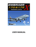
2.61
Energy efficiency ratio (EER) at full load
Indice di efficienza energetica (EER) a pieno regime
Niveau de rendement énergétique (EER) à pleine charge
Índice de eficiencia energética (EER) a pleno rendimiento
Energie-Effizienz-Schlüssel (EER) bei Vollast-Nutzung
Energie-Efficiëntie-Verhouding (EER) volle belastingSchlüssel
Energy efficiency class on a scale of A (more efficent) to G (less efficient)
Classe di efficienza energetica su una scala da A (bassi consumi) a G (alti consumi)
Classement selon son efficacité énergétique sur une échelle allant de A (économe) à G (peu économe)
Clase de eficiencia energética en una escala desde A (bajo consumo) hasta G (alto consumo)
Energieeffizienzklasse auf einer Skala von A (niedriger Verbrauch) bis G (hoher Verbrauch)
Energieefficiëntieklasse op een Schaal van A (efficiënt) tot G (inefficiënt)
Heating / Riscaldamento / Chauffage / Calor / Heizfunktion / Verwarming
Heat output (kW) / Potenza di riscaldamento (kW) / Puissance de chauffage (kW)
Potencia de Calor (kW) / Heizleistung (kW) / Verwarming-svermogen
Water cooled / Raffreddamento ad acqua / Refroidissement par eau / Frío por agua / Wasserkühlung / Watergekoeld
Air cooled / Raffreddamento ad aria / Refroidissement par air / Frío por aire / Luftkühlung / Luchtgekoeld
Cooling/heating / Raffreddamento/riscaldamento / Refroidissement/chauffage / Frío/Calor / Kühlfunktion/Heizfunktion / Koeling/Verwarming
Cooling only / Solo raffreddamento / Refroidissement seulement / Sólo Frío / Køling / Alleen koeling
3.55
Cooling output (kW) / Potenza refrigerante (kW) / Puissance frigorifique (kW)
Potencia refrigerante (kW) / Kühlleistung (kW) / Koelvermogen (kW)
Type
Tipo
Type
Tipo
Typ
Type
680
A
HMCI 125 F-EH
Annual energy consumption (kWh) in cooling mode
Consumo annuo di energia (kWh) in modalità raffreddamento
Consommation annuelle d'énergie (kWh) en mode refroidissement
Consumo anual de energía (kWh) en modo Frío
Jährlicher Energieverbrauch (kWh) im Kühlbetrieb
Jaarlijks Energieverbruik (kWh) in Koelstand
Energy efficiency class on a scale of A (more efficent) to G (less efficient)
Classe di efficienza energetica su una scala da A (bassi consumi) a G (alti consumi)
Classement selon son efficacité énergétique sur une échelle allant de A (économe) à G (peu économe)
Clase de eficiencia energética en una escala desde A (bajo consumo) hasta G (alto consumo)
Energieeffizienzklasse auf einer Skala von A (niedriger Verbrauch) bis G (hoher Verbrauch)
Energieefficiëntieklasse op een Schaal van A (efficiënt) tot G (inefficiënt)
Cooling / Raffreddamento / Refroidissement / Frío / Køling / Alleen koeling
Model
Modello
Modèle
Modelo
Modell
Modell
Manufacturer / Costruttore / Fabricant / Fabricante / Hersteller / Fabrikant
NOTES
NOTES
HOKKAIDO Srl
14, Via della Salute
40132 Bologna - Italy
Tel. +39.051.41.33.111
Fax +39.051.41.33.112
www.hokkaido.eu
www.termalgroup.com
Due to on-going technological development of the Products by the Manufacturer, we
reserve the right to vary the technical specifications at any time and without notice.