1
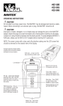
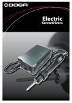
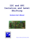
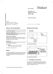
Installation / Operation / Maintenance
StaticControls
TSN75E User Manual
7.5kV Static Neutralizing Power Supply
General Description
The Static Clean Static Neutralizing System consists of
two parts:
• A high-voltage line-frequency (50/60Hz) transformerbased AC Power Supply
• An Applicator (air ionizer in the form of a bar or rod, air
blower, air gun, air nozzle, or air knife).
The system is designed to create an abundance of bipolar
air ions in a “field” which tends to neutralize electrically
charged materials (paper, plastic, glass, wood, etc.) that
pass through it.
The Static Neutralizing Power Supply
The TSN75E Power Supply is an output-current-limited
AC-voltage source, providing appropriate ionization at the
Applicator and safety to the user. An internal step-up
transformer operates off the mains, and its high-voltage
(HV) secondary is coupled to the Output Ports through a
resistive damping circuit; the Resistive Output Coupler
provides optimal voltage limiting and load regulation with a
wide range of Applicator equipment, enhancing the
reliability of the Neutralizing System. The TSN75E includes
a dual-voltage selector switch to support operation with a
multitude of international mains power systems.
Locating the Power Supply
Locate the Power Supply as close as possible to the
applicator using its mounting flanges to securely fasten
the unit in place. Choose a location free of oil, water and
contamination. T h e P o w e r S u p p l y a n d a t t a c h e d
Applicator(s) must not be located outside where they
might be exposed to rain, snow and other elements .
Avoid areas where ambient temperature is continuously in
excess of 49°C/120°F.
Mount the Power Supply so that the HV Output Ports are
facing down or to either side to prevent entry of foreign
material. Unless specified differently in the purchase order,
each static bar is equipped with an integral standard 6-ft.
(1.8m) length of HV cable. This length allows the
installation of two static bars up to 10 ft. (3m) apart
connected to one centrally-located Power Supply. Slack
(i.e. excess length) in the HV cable can be eliminated by
coiling, using a minimum number of turns to avoid excess
stress/strain and degradation of dielectric strength in the
insulation of the cable, possibly leading to early failure.
Grounding the Power Supply
For safety and reliable function, the TSN75E Power
Supply must be grounded through both mains connection
(i.e. IEC-320 connector) and chassis protective-earth (PE)
connection. The PE connection must be made between
the ground stud (located in the lower-center area of the
I/O panel) and a reliable and properly tested electrical
earth (e.g. mounting stud or similar equipment attachment
location).
CAUTION: IT IS IMPORTANT THAT ONLY QUALIFIED
PERSONNEL FAMILIAR WITH HANDLING HIGH
VOLTAGE ELECTRICAL EQUIPMENT BE TRUSTED
TO INSTALL, SERVICE, AND TROUBLESHOOT THIS
EQUIPMENT. FEEL FREE TO CONSULT THE
FACTORY IF YOU HAVE ANY QUESTIONS.
Static Clean International • 15 Adams St., Burlington, MA 01803
Tel: 781-229-7799 Fax: 781-229-4555 • www.staticclean.com
10/12
Installation / Operation / Maintenance
StaticControls
Model TSN75E Specifications
Mounting the Power Supply
The TSN75E Power Supply provides two mounting
flanges on opposing sides of the chassis. Each flange
includes two slotted holes and one open-end slot,
supporting a range of screw locations in both axes on the
mounting plane. Using the dimensions herein provided,
drill and tap two or four mounting holes (10-32 or 1/4-20
are adequate to secure the Power Supply).
The preferred Power Supply orientation is with the I/O
panel face down; face left or right is acceptable. The
Power Supply must not be oriented with the I/O panel
face up. Avoiding this will prevent contaminants traveling
down the HV cable and into the Output Port sockets,
possibly generating a parasitic conductive path
overloading the supply or overheating and degrading HV
insulation materials. Looping of the HV cable below the
height of the Output Ports is also recommended to divert
fluids away from the HV sockets.
Power Supply Input Voltage
2
The TSN75E Power Supply dual-voltage selector enables
the user to connect the input to single-phase, 50/60Hz
mains power at 120VAC or 240VAC (lower mains voltages
generate proportionally lower output voltage in the
TSN75E and other “linear transformer” power supplies). A
detachable three-conductor line cord with a 115V
ground-prong plug is supplied with the unit. Be sure to
plug the cord into a grounded three-prong receptacle
(alternatively, the plug can be cut from the cord so that the
pigtail can be “hard-wired” if desired). Line cords with US,
UK or Euro 230V plugs (sold separately) are available and
must be specified at the time of order.
VERY IMPORTANT – Before connecting
mains power to the unit, be sure to
check or set the voltage selector switch
(located above Output Ports on I/O
panel) to the proper position -- either
120V (115V) or 240V (230V). Failing to
correctly set the switch can damage or
destroy the Power Supply, increase risk
of shock to operators and/or void the
warranty.
Remember: Proper input-grounding of
the TSN75E Power Supply is essential
to the safety of the user and proper
operation of the equipment. A power
cord with a ground prong as supplied (or
equivalent wiring) must be used to assure that the Power
Supply is grounded. For added convenience and safety,
these units come equipped with a fuse and a lighted
on/off switch. A spare fuse is included, stowed inside the
removable fuse drawer.
Routing the Applicator HV Cable
The Applicator HV cable may be sheathed in a conductive
shield or in a non-conductive flex-tube, or unsheathed.
Unsheathed cable must be dressed, mounted and routed
so as to guarantee a minimum (solid or air) dielectric
spacing of 1/4 in. between all points on the cable
insulator and all other conductive surfaces and objects
(including metal mounting hardware and mounting-surface
corners).
A minimum bending radius (referenced to wire centerline)
of 1 1/4 in. applies to all cables.
Special care should be taken to assure the HV cable will
not be subjected to tugging, snagging, pinch-points or
moving parts that may cut, nick, abrade or wear-down the
cable insulation and/or sheathing.
Failure to follow the above-described precautions will likely
result in premature failure of the HV cable and void the
warranty.
Connecting Applicator to Power Supply
Applicator HV cables can be configured for various
features such as shielding, jacketing and termination
styles. The following are standard feature combinations
requiring either a two-wire connection (i.e. HV and ground)
or a one-wire connection (i.e. HV only) to the Power
Supply:
Set Screw
Cable
Nut
Spacer
Spring Contact
• shielded HV cable with a braided-wire sleeve ground
conductor fully enclosing the HV cable or a
standard/discrete-wire ground conductor alongside a
protective flex-tube jacket enclosing the HV cable (twowire connection)
• unshielded HV cable with or without a protective flextube jacket (one-wire connection; for unjacketed
configuration see the following section on terminator-plug
assembly procedure)
FOR SAFETY – Before proceeding verify that the mains is
disconnected and that the TSN75E is unpowered.
1. Fully insert Applicator HV cable plug connector(s) into
TSN75E Output Port socket connector(s) after
removing dust covers, if present.
2. Thread retaining nut(s) into Output Port socket(s) and
finger-tighten. Do not use tools!
3a. For shielded HV cable, remove outer (1 of 2) 8-32 hex
nut (with star washer) from the TSN75E ground stud.
Place ring terminal(s) of HV-cable ground/shield (green
or black) wire(s) over TSN75E ground-stud (and PEwire terminal). Replace and tighten hex nut. This
connection grounds the HV cable shield (to minimize
EMI) as well as the Applicator(s) ground/reference
electrodes.
3b. For unshielded HV cable (note: not recommended for
EMI-sensitive applications), connection of the
Applicator(s) ground/reference electrodes must be
made by wire (e.g. to TSN75E ground stud or
alternative earth location) or directly (through
conductive mounting hardware if applicable).
Applicator ground/reference wiring or mounting
connection points vary with different forms of ionizing
equipment. Examples include:
• mounting (i.e. bolt-head) slot in aluminum “outer
bar” shell of a static bar
• tip of an ionizing air-nozzle
4. Verify that TSN75E dual-voltage selector switch,
located above HV Output Port sockets on I/O panel, is
set to match mains voltage (100V...120V or
200V...240V).
5. After Applicator(s) and Power Supply have been
properly installed, secured and grounded, mains power
may be connected (e.g. plug the power supply line
cord into a properly grounded 3-wire AC outlet). Verify
that mains voltage and frequency match those
specified on TSN75E nameplate. Do not remove
ground prong or ground wire from the line-cord or use
a three-to-two prong adapter.
HV Cable Termination Using Plug Connector
Kit (unshielded unjacketed HV cable only)
After mounting Applicator(s) and Power Supply, routing HV
cable(s) and cutting to desired length, attach HV cable
connector as follows (refer to figure at top-left of page for
kit parts illustration):
1. Slide retaining nut over cable with threaded section
trailing (i.e. facing the cable end).
2. Slide spacer over cable.
3. Carefully strip 3/16 in. to 1/4 in. of insulation from end
of HV cable, exposing conductor.
4. Insert conductor into entry hole in base of spring
contact.
5. Tighten set screw in base of spring contact (use 1/16in. Allen wrench) until conductor strands are held firmly
in place.
Installation / Operation / Maintenance
7.5 kV Static Neutralizing Power Supply
Specifications: TSN75E
Type:
high-voltage linear transformer
with resistive output coupling
Input Voltage:
Frequency:
Output Voltage:
Input Current:
Input Fusing:
Output Current:
Ambient Temperature:
Line Cord:
Optional Cords:
Weight:
Dimensions:
. . . . . . . . .120/240 VAC
. . . . . . . . .50/60 Hz
. . . . . . . . .7.5 kVRMS nom.
. . . . . . . . .0.2/0.1 A max.
. . . . . . . . .0.315 A time-delay
. . . . . . . . .3 mA max.
. . . . . . . . .< or = 40C
. . . . . . . . .6’ detachable
with NA 3-prong grounded plug
. . . . . . . . .UK, Euro, and NA
240V grounded plugs available
. . . . . . . . .6.0 lb
width: . . . . . .6.8 in.
height: . . . . . .4.2 in.
depth: . . . . . . .6.9 in.
3
Maintenance
Both the TSN75E Power Supply and the Applicator must
be kept clean and free of water, oil, grease, solvents and
other contaminants. Contamination or arc-over in the
“Applicator” can degrade the longevity and reliability of
the Static Neutralizing System.
Troubleshooting
Only a qualified person familiar with handling HV
equipment should attempt to troubleshoot and service
this equipment.
• Power-off system (i.e. disconnect mains) and
disconnect all applicators.
• Confirm that grounds are reliable and secure.
• Confirm mains voltage and frequency are within
specifications.
• Confirm that dual-voltage selector switch setting is
correct for the verified mains voltage.
• If the switch was set to 240V (230V) and the
mains voltage is in lower range
(100V...120V), change the switch setting to
120V (115V) and power-on the unit. If this
does not correct the problem, consult the
factory.
• If the switch was set to 120V (115V) and the
mains voltage is in higher range
(200V...240V), the input fuse (located inside
the removeable fuse drawer beside the inlet
connector) must be replaced. A spare fuse
is also located in the fuse drawer. Discard
the original fuse and replace with the spare
fuse, change switch setting to 240V (230V)
and power-on the unit. If this does not
correct the problem, consult the factory.
• Confirm fuse continuity (visually or, preferrably, by
ohmic testing). Replace if necessary.
• Confirm that the power switch is ON.
Please also note that HV test attenuators/probes may
significantly load high-impedance nodes (e.g.
“shockless” ionizing electrodes) within a Static
Neutralizing System, resulting in measured voltages
much lower than those during normal (i.e. unloaded or
unprobed) operation. For further assistance, please
consult us at our factory.
Phone: 781-229-7799 Fax: 781-229-4555
Operation
Before applying mains power, be sure that the TSN75E Power Supply is secure in its mounting, all ground and highvoltage connections are reliably made and secure, mains voltage and frequency are appropriate and that the “Applicator”
is clean and correctly installed. Apply mains power and set the TSN75E power switch to the ON position.
Servicing and Repairing Power Supply In-the-Field
In the event of damage to or failure of a power-supply component, the user may choose to repair the TSN75E Power
Supply at his facility or to send the unit to the factory for repair. For in-the-field repair, please refer to the TSN75E Service
and Repair Manual for replacement component part numbers, pricing, etc. and instructions.
Static Clean International • 15 Adams St., Burlington, MA 01803
Tel: 781-229-7799 Fax: 781-229-4555 • www.staticclean.com
4