1
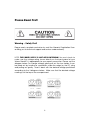
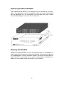
1.Unpacking the Waves MaxxBCL
After unpacking the MaxxBCL unit, please check it carefully for any damage.
If any damage is found, immediately notify the carrier that brought you the
package. You, the consignee, must instigate any claim. Please retain all
packaging in case of future re-shipment.
Mounting the MaxxBCL
Before connecting MaxxBCL, be sure to securely mount it in a standard 19”
studio rack-mount away from heat and moisture. We recommend using
the supplied plastic washers between MaxxBCL and the mounting bolts to
protect MaxxBCL’s front panel from scratches. Alternatively, for desktop use,
attach the four rubber feet to the bottom of the MaxxBCL.
TABLE OF CONTENTS
Important Safety Considerations ............................................................. 4
Package Content ..................................................................................... 4
Unpacking the Waves MaxxBCL ............................................................... 5
Mounting the MaxxBCL............................................................................. 5
Introduction .............................................................................................. 6
MaxxBCL Features .................................................................................... 6
MaxxBCL Applications .............................................................................. 7
Front Panel Explanation ............................................................................ 7
Rear Panel Explanation ............................................................................ 8
Connecting The MaxxBCL ........................................................................ 9
Main Power Supply .................................................................................................................................. 9
Replacing the fuse: ................................................................................................................................. 9
Audio Connections (Rear Panel) ......................................................................................................... 10
Analog Connections: ........................................................................................................................... 10
Digital Connections: ............................................................................................................................ 10
Calibration: ........................................................................................................................................... 11
Sync & Word Clock Connections (Rear Panel): ................................................................................. 12
Operating the MaxxBCL ......................................................................... 13
MaxxBCL Overview ............................................................................................................................... 13
Compression with the Renaissance Compressor ............................................................................. 13
Opto ....................................................................................................................................................... 14
ARC™ (Auto Release Control) .............................................................................................................. 14
Low level compression (S curve)......................................................................................................... 14
Bass Enhancement with MaxxBass™? ................................................................................................ 15
How does the MaxxBass™ work? ........................................................................................................ 15
What does the MaxxBass™ do? .......................................................................................................... 15
Limiting and maximizing with the L2 .................................................................................................. 16
About level and resolution in the L2 ................................................................................................... 17
Maximum level ..................................................................................................................................... 17
Details on using IDR™ (Increased Digital Resolution) ...................................................................... 17
Controls & Displays ................................................................................ 18
Front Panel Controls ............................................................................................................................. 18
Sample Rate .......................................................................................................................................... 18
Input Selector:....................................................................................................................................... 18
Sync ....................................................................................................................................................... 18
Quantize ................................................................................................................................................ 18
Presets....................................................................................................................................................19
Input....................................................................................................................................................... 20
Compressor Controls ........................................................................................................................... 21
MaxxBass™ Controls ............................................................................................................................ 23
Limiter Controls ..................................................................................................................................... 24
Examples Of Applications ...................................................................... 25
Example A: Using the MaxxBCL as a Sound Reinforcement (SR) enhancing module. .................. 25
1
Example B: MaxxBCL as a drum/bass controller (inserted in a subgroup where drums or/and bass
assigned to) .......................................................................................................................................... 26
Example C: Digital mixing desk insert/FX (recording/mixing) ......................................................... 26
Example D: Using MaxxBCL as a D/A converter (for monitoring) .................................................... 27
Connection ........................................................................................................................................... 27
Example E: Digital domain mastering ................................................................................................ 27
Sound Reinforcement Applications ........................................................ 28
Broadcasting Applications ..................................................................... 30
The MaxxBCL used with live music ..................................................................................................... 30
The MaxxBCL used for News Production. ........................................................................................... 30
The MaxxBCL used on the output of a DJ mixer. ............................................................................... 31
The MaxxBCL used in broadcast production. ................................................................................... 31
The MaxxBCL used to increase overall station signal loudness and bass. ................................... 32
The MaxxBCL used for live music feeds over ISDN. .......................................................................... 32
The MaxxBCL used for loading music into automation systems. .................................................... 33
Known Issue ............................................................................................ 33
Technical Specifications ........................................................................ 34
ADC (@44.1kHz): ................................................................................................................................... 34
DAC (@44.1kHz): ................................................................................................................................... 34
Analog output stage: ........................................................................................................................... 34
Latency (in samples): ........................................................................................................................... 34
Front panel dedicated buttons: .......................................................................................................... 35
Front panel dedicated rotary controls: .............................................................................................. 35
Front panel dedicated numeric displays: ......................................................................................... 35
Front panel displays:............................................................................................................................ 35
Back Panel ............................................................................................................................................ 36
Dimensions: ........................................................................................................................................... 36
Troubleshooting & Frequently Asked Questions ..................................... 36
Contact Waves Sales and Technical Support ........................................ 37
Warranty ................................................................................................. 38
Governing Law and Severability ......................................................................................................... 39
2
Please Read First!
Warning – Safety First!
Please read, complete and return by mail the Warranty Registration Form
entitling you to technical support and service-under-warranty.
NOTE: THE POWER SUPPLY IS NOT AUTO-SWITCHING! You must check to
make sure the voltage rating shown directly on the back panel of your
Waves MaxxBCL is appropriate for your power connection. Please see the
diagram below. To change voltage, gently pull out the fuse holder. It can
be pried out by inserting a screwdriver under the edge by the IEC plug
and pulling out gently. Insert it back with the desired voltage positioned
according to the 3 diagrams below. Make sure that the desired voltage
marking is at the top of the compartment.
3
Warning: Class 1 laser product (single-mode).
Important Safety Considerations
1. Securely mount the Waves MaxxBCL in a 19” studio rack away from rain,
moisture, liquids, heat sources or fire using the four supplied mounting bolts.
(Plastic washers are provided to prevent scratching). Apply the rubber feet
for desktop use.
2. In case of damage to the Waves MaxxBCL due to spilled liquids or
physical damage from knocks or dropping, repairs should be performed
by qualified service personnel only.
3. Read all operating instructions.
4. Do not allow children to use the MaxxBCL without adult supervision.
6. Do not overload audio inputs or outputs. Waves will not be responsible for
damage caused to other equipment (such as speakers) through misuse.
7. Do not block the ventilation grills that are located the sides of the unit.
Package Content
Your new MaxxBCL package should contain:
The Waves MaxxBCL unit
• 110 V USA power cable
• 220 V European power cable
• Three (3) sets of four (4) mounting bolts each
• Spare fuse
• Four (4) rubber “feet”
• Four (4) plastic washers
• User Manual
• Quick Start Guide
• Registration card
• Warranty information
4
Unpacking the Waves MaxxBCL
After unpacking the MaxxBCL unit, please check it carefully for any damage. If any damage is found, immediately notify the carrier that brought
you the package. You, the consignee, must instigate any claim. Please
retain all packaging in case of future re-shipment.
Mounting the MaxxBCL
Before connecting MaxxBCL, be sure to securely mount it in a standard 19”
studio rack-mount away from heat and moisture. We recommend using
the supplied plastic washers between MaxxBCL and the mounting bolts to
protect MaxxBCL’s front panel from scratches. Alternatively, for desktop use,
attach the four rubber feet to the bottom of the MaxxBCL.
5
Introduction
Welcome to the Maxx BCL User Manual. Be sure to read the safety
considerations on page 3 of this manual before you plug-in and switch on
the MaxxBCL’s power.
Thank you for choosing the Waves MaxxBCL. Please spend some time reading
through this manual so that you obtain the best possible performance from
the unit. All Waves products are carefully designed and engineered for
cutting-edge performance and world class reliability. For more information
about our products please visit our web site at:
http://www.waves.com
MaxxBCL Features
• Full 48-bit internal processing.
• Supports sampling rates up to 96kHz.
• Waves IDR™ (Increased Digital Resolution) re-quantization for direct digital
16-bit recorders.
• Waves MaxxBass™ (2nd generation) low frequency enhancer.
• Waves Renaissance Compressor dynamics compression.
• Waves ARC™ (Auto Release Control) technology for dynamically
controlling release times for maximum level with minimum artifacts.
• The L2, the renowned precision brick wall limiting and level maximizing
processor.
• A wide variety of analog and digital connectors for compatibility with all
popular formats.
• 16/24-bit digital I/O
•Superb-quality AD/DA conversion using 24-bit converters and transformerbased analog input/output stages.
6
MaxxBCL Applications
The MaxxBCL performs all digital processes with 48-bit internal precision
(double precision). The internal processing is followed by requantization
(wordlength reduction) from the internal 48-bit data to 16 or 24-bit output
wordlengths. (Analog output always used the full 24-bit wordlength). The
system can also be used to requantize 24-bit input signals to 16-bit (via the
digital outputs only). This is suitable for 16-bit recording equipment such as
DAT and an ideal function for CDR applications.
The “Examples of Applications” chapter (p. 27) includes detailed examples
of MaxxBCL applications. However, you can use the MaxxBCL in many other
setups according to your needs, such as:
• Sound Reinforcement Applications
• Stage Monitoring
• Broadcasting or Webcasting
• Mastering
• Connecting the MaxxBCL to an Insert on a mixer channel
• Recording a mix through the MaxxBCL to your master recorderA/D and •
D/A conversion
Front Panel
1. Global Controls: Select/display operating sample rate, input type, sync
source,quantize type.
2. Presets: Store/Recall the currently active MaxxBCL setting preset.
3. Input Meters: Display the input signal level.
4. Input Trim Rotary Switches (Left/Right): Control analog input level.
5. Compressor Section Controls: Display/Set compressor parameters
and controls.
6. MaxxBass™ Section Controls: Display/Set MaxxBass™ parameters and
controls.
7. Limiter / UltraMaximizer Section Controls: Display/Set Limiter/
UltraMaximizer parameters and controls.
8. Output Meters: Display the output signal level
7
Rear Panel
1. Main Power Supply: Connects the MaxxBCL to the power supply.
2. Word Clock: Provides digital synchronization interface.
3. Digital I/O Interface: Allows for digital I/O connection of various
types.
4. Analog I/O Interface: Allows analog I/O connection of various
types.
8
Connecting The MaxxBCL
Main Power Supply
Important! 100, 120, 220 or 240 volt selectable - THE POWER SUPPLY IS
NOT AUTO-SWITCHING!
You must check to make sure the voltage rating shown on the back panel
of your MaxxBCL is appropriate for your power connection. Please see the
“Read First!” section.
The power cable socket and fuse-holder with voltage selector are located
together on the back panel of MaxxBCL. Plug the supplied cable into
the back of the MaxxBCL and into your power connection. Switch on the
MaxxBCL using the on/off power switch located on the front panel. When
you switch the power on, the front panel LED displays will illuminate.
Replacing the fuse:
If the fuse blows, switch off the power and unplug the unit. Pull off the fuse
holder (see diagram above) and replace the fuse. Do not forget to replace
it with the proper voltage selection indicated!
• We suggest using the following UL listed fuses:
- for 100/120 V – use a 200 mA fuse
- for 220/240 V – use a 100 mA fuse
• We also suggest using slow blow fuses.
9
Audio Connections (Rear Panel)
Analog Connections:
MaxxBCL
accepts two types of connectors for left and right analog and
outputs.
The connector types are:
1. XLR/TRS combo inputs connector type for balanced / eunbalanced inputs.
2. XLR connector type for balanced outputs.
3. TRS (1/4”) jack connector type for balanced or unbalanced outputs.
Digital Connections:
The MaxxBCL accepts three types of digital inputs and outputs:
1. XLR type input/output connectors for AES/EBU signals.
2. RCA type input/output connectors for S/PDIF signals.
3. Optical type input/output connectors for S/PDIF signals.
S/PDIF input/output uses RCA or Optical connectors (mutually exclusive).
The input format is selected using the Coaxial/Optical selector switch.
10
Input/Output Calibration controls:
The Calibration controls allow you to calibrate the signal output that runs
from your analog device (going to the MaxxBCL) to the MaxxBCL’s input,
and the analog output of the MaxxBCL (going to the unit following the
MaxxBCL in the signal chain). This allows you to get the maximum headroom available in your audio working environment.
Input Calibration:
Set your analog device to its maximal output level and set the input rotary
switches on the MaxxBCL front panel to unity gain. Now adjust the input
Calibration so that your peak signals are between -6 and 0dB(FS) on the
input meters.
Output Calibration:
To adjust the MaxxBCL’s output, set the Calibration control so that the input
level on your analog device (the one that follows the MaxxBCL in the signal
chain) does not exceed Unity gain.
Options: Input: + 9, 12, 15, 18, 20, 24 dBu. Output: + 9, 12, 15, 18, 20, 24
dBu
11
Sync & Word Clock Connections (Rear Panel):
The MaxxBCL can be connected to an external word clock source or you
can use MaxxBCL’s internal clock source. The external clock source connector is BNC type.
An external word clock is utilized for applications that require synchronization with other digital audio devices. The internal clock setting is selected
on the front panel only when using the MaxxBCL’s analog inputs.
The Termination On/Off switch enables the MaxxBCL to perform wordlength
impedance matching when multiple word clock sources are chained together.
Correct termination of word clock inputs is crucial for a stable clock configuration. As the frequency of a word clock signal increases, termination
requirements become more critical for precise transmission. In order to
ensure the integrity of the clock waveform, each connection should be
terminated by a 75 ohm load impedance. Over-termination (a load impedance lower than 75 ohms) will attenuate the signal excessively, while
under-termination (a load impedance greater than 75 ohms) introduces
overshoot and other waveform distortions. Both conditions compromise
clock accuracy.
12
Operating the MaxxBCL
MaxxBCL Overview
The MaxxBCL is a hardware version of a commonly used software-based
mastering chain used by mastering engineers worldwide. It consists of a
Waves Renaissance Compressor (RenComp), the 2nd generation MaxxBass™ and the L2 Ultramaximizer plug-ins.
We have found that the technique of maximizing levels and enhancing
low-end perception gives great results in the world of live sound. Efficient
use of signal can actually result in a much higher impact and efficiency
from a specific PA system. At the same time, the PA receives maximum
protection from overload.
For sound reinforcement, the MaxxBCL can be used to gain more bass
using the system’s efficient range to generate more bass response without
taxing the speakers, and to maintain transparent compression and brick
wall limiting to keep maximum dynamic range without generating feedback. As such, the MaxxBCL can be used on the FOH (Front Of House) or
stage consoles or in permanent installations.
While the MaxxBCL is designed primarily for sound reinforcement applications, it is also able to perform recording, post production and broadcasting functions as well.
Compression with the Renaissance Compressor
The Renaissance Compressor is a classic warm compressor and expander.
It combines technologies that originally evolved from the groundbreaking
C1 Compressor/Gate and the acclaimed L1 Ultramaximizer software processors with Waves revolutionary ARC™ (Auto Release Control) technology.
The ARC™ algorithm is also capable of delivering significantly greater RMS
levels (lower peak/RMS ratio) for heavier compression levels.
The Renaissance Compressor features two compression behaviors:
Electro: The ‘Electro’ mode has a release time behavior that becomes
increasingly faster as the gain reduction approaches zero, but only when
gain reduction is less than 3dB. When gain reduction is above 3dB, the
release time becomes slower, behaving more like a leveler in high gain
reduction situations. Therefore, when used with moderate compression, the
Electro mode produces a great increase in RMS (average level), and is
ideal for “loud” applications, such as voiceover, music mastering, live PA,
etc.
13
Opto
The ‘Opto’ mode is actually the inverse of Electro. Opto-coupled behavior
always “puts on the brakes” as the gain reduction approaches 0dBFS, i.e.,
the release time gets slower as the “needle comes back to zero”. As in
Electro, this is true only when the gain reduction is less than 3dB.
ARC™ is a system designed to dynamically choose the optimal release
value for a wide-ranging input. ARC™ reacts much the way a human ear
expects, and can produce increased RMS level with greater clarity.
ARCTM (Auto Release Control)
The Release control behavior of the MaxxBCL compressor and limiter is
based on the Waves ARC™ technology. This technology allows for calculating an optimal release time for the dynamic gain attenuation in a program
dependent manner.
In many uses of compressors, the exact choice of time constants is set as a
careful choice of reaction to RMS level and peak transients. To allow more
constant compression with fewer artifacts, the release time must change
dynamically to control different parts of the signal. In ARC™, as in the human ear, RMS and peak transients are analyzed and reacted to differently.
In general, the release is faster for peak transients and slower for the overall
RMS level.
For instance, with a relatively constant compression of 4dB, peaks beyond
this require faster release times. The ARC™ system does exactly this, varying the release time to fit the ear’s expectations while increasing RMS, and
without creating distracting artifacts. In this way, the Renaissance Compressor can serve as a leveler and as a fast compressor simultaneously. This
feature also serves gentle mastering applications quite well, but generally
with slower release times. This would apply to music genres such as classical music.
Low level compression
For settings with deep Thresholds (below -40dB) and low ratios (below 1:2),
the RenComp compression curve behaves as a “low level upwards” compressor. With such settings, the dynamics of high level signals are unaltered,
and only the dynamics of low level signals are altered, pulling their level
upwards. This is great to reveal low-level details of the signal, while retaining
the transients and transparency of high level signals.
14
Bass Enhancement with MaxxBassTM
MaxxBass™ generates harmonics that are selectively added to the signal.
These harmonics cause the ear to perceive low bass frequencies that may
not actually be present in the signal.
This psychoacoustic phenomenon, explained below in further detail, is
used in a mixing or mastering situation to enhance the bass response of
the target playback system. Even in a good mix, MaxxBass™ will create a
fatter, clearer and overall better bass presence.
The same MaxxBass™ generated enhancement principle is also applicable for installed systems such as commercial sound systems, theme parks,
outdoor distributed systems, personal stereo systems, and more. To see
more MaxxBass™ applications, visit www.maxxbass.com.
How does the MaxxBassTM work?
Even though you can hear a bass guitar from a small speaker, you are
not hearing the main note-the fundamental frequency. This is because
the speaker can not physically produce such a low pitch. However, the
harmonics of the bass guitar are indeed coming from the speaker, and
your ear interprets these harmonics and creates the “missing fundamental” in your mind. This is a well-known psychoacoustic principle. MaxxBass™
extends the perceived frequency response of a system up to two octaves
below its physical limitation.
What does MaxxBassTM do?
The input signal is split into two parts through an 18dB/Oct crossover; the
crossover Frequency (controlled by the Frequency knob) determines the
split point. High frequencies are transparently passed to the output (to be
added back to the bass). The bass signal is analyzed by the MaxxBass™
processor, which creates a specific series of harmonics of these low frequencies. Since the dynamics and the loudness of the original bass are
duplicated in these harmonics, the result is the most natural sounding enhancement of the original bass.
The MaxxBass™ Harmonics signal is designed to basically replace the original low frequency signal with its high frequency harmonics. By switching the
HPF in and out you can decide whether to retain or remove the original low
frequencies.
When you target a specific speaker system with a known low cutoff, switching the HPF in can help removing excessive load from the speakers without
degrading their performance. This is useful when mixing for a specific set
of speakers or systems, such as those in commercial installations, theme
parks, kiosks, etc. This is also useful if you want to eliminate or reduce low
15
rumble from your venue.
When the target speakers are unknown, or they consist of a range of speakers, switching the HPF off and retaining the original low frequencies allows
for a more flexible compromise that can suit a wider range of speakers.
This is useful when you master a CD or have a PA system with several types
of speakers. When using MaxxBass™ on a PA system it is immediately noticeable that the system produces more bass while load is reduced. The
mechanism which MaxxBass™ uses can produce the effect of clean low
frequencies which would ordinarily excite rooms. This is a huge advantage
for installed systems. For example, in a live sound situation you might encounter a venue with a low frequency rumble that causes low frequency
oscillation and/or feedback. MaxxBass™ allows you to “bypass” these problematic low frequencies by replacing them with a combination of higher
frequencies that are above the rumble, while retaining the impact and
feeling of the bass for the audience.
Limiting and Maximizing with the L2
The MaxxBCL unit uses the third-generation L2 Ultramaximizer processor,
combining an advanced peak limiter, level maximizer and a high performance requantizer and dithering system called IDR™ (Increased Digital
Resolution). In addition, the L2 processor includes ninth-order noise-shaping
in the IDR™ implementation.
While the operation of conventional limiters is well understood, the limiter
section of the L2 Ultramaximizer is capable of a very fast, overshoot-free
response, and once the limiter threshold has been set, you can then go on
to define the actual peak level that the processed signal will reach. Once
set, limiting and level re-calibration becomes a one-shot process.
For mastering purposes, the peak level of the processed signal would normally be set to 0dB, or just below 0dB. Because a typical digital music signal contains multiple high-intensity short-duration peaks, simple normalization of the signal may still result in a low average level. However, when using
the L2 Ultramaximizer, it is generally possible to significantly increase the
average level of a typical audio signal without introducing any audible side
effects. In the event that a deliberately limited sound is required, there is
more than adequate range in the limiter parameters to recreate ‘vintage’
effects such as level pumping or severely limited dynamic range.
When using the MaxxBCL in a digital based system, it is recommended that
the MaxxBCL be used last in the processing chain. Failure to do this will not
prevent the MaxxBCL from working, but you should be aware that the absolute brickwall limiting will be compromised and you might need to re-limit
your signal to maintain the original level.
16
About level and resolution in the L2
Maximum level
The maximum level of a digital signal is generally governed by the source’s
highest peak. Today’s demanding production environments require the
average levels to be much higher than in the past, and with the accompanying risk of digital clipping comes the need for precision control of the
maximum peak level.
The L2’s brickwall peak limiter acts as a ‘protected gain’ control. It lets you
increase the gain as you choose, as well as define a maximum output ceiling which the signal is never allowed to exceed. The L2 limiter only reduces
the applied gain locally when it anticipates that a clip is about to occur.
By transparently controlling signal peaks, the entire level of the source can
be raised several more dB, resulting in a higher average signal level. For
real time processing, the normalization process of disk-based systems is
not possible, as it is nearly impossible to know the highest peak of a source
in advance. The L2 prevents overshoots by utilizing a “look-ahead” technique, which lets it anticipate and reshape peaks in a way that produces a
minimum of audible artifacts (at the expense of introducing a 64 sample
throughput latency).
Details on using IDRTM (Increased Digital Resolution)
In the MaxxBCL, all processing is done at high resolution; in this case, with
48-bit precision. When processing at a high bit depth, you must decide
how you want to finally reduce this long wordlength for the output. Any
digital signal processing that alters the original digital data (mixing, gain
changes, EQ, dynamic processing, etc.) generally increases the number
of bits required to represent the signal. Conventional truncation results in a
loss of signal-resolution each time the signal is processed.
The solution is to properly dither and noise-shape a signal each time the
wordlength is increased and then reduced (such as nearly every digital
signal process will require). This is to maintain the best possible quality at
the reduction phase.
Inside the MaxxBCL, all data is required to use 48 bits to represent the signal, even when MaxxBCL is processing a 16-bit input signal. Therefore, even
when the output from the MaxxBCL is 24-bit, the IDR™ system is used and
captures up to 27 bits of perceived resolution for the output signal. Truncating the 48-bit internal signal at the final output will result in a rounding error
which produces distortion at low signal levels and a loss of digital resolution
that can never be recovered. Needless to say, IDR™ is much more critical
in the case of 16-bit output into 16-bit digital devices, but it is also beneficial when the output is 24-bit.
17
Controls & Displays
Front Panel Controls
Sample Rate: Select / Display the MaxxBCL sampling rate. MaxxBCL supports operating sample rates up to 96kHz. You can only change the signal
sample rate when the MaxxBCL’s Sync mode is set to Internal. At the other
settings the MaxxBCL locks to the digital stream or external Word Clock
source. The MaxxBCL will automatically detect and display the sample rate
for all other Sync modes.
Options: 44.1kHz, 48kHz, 88.2kHz, 96kHz.
Input Selector:
Select / Display currently active MaxxBCL input. Push the Input Select button
to toggle through the selection according to the type of audio input signal
you are using.
Options: A=Analog, SPDIF=S/PDIF (RCA / Optical)*, AES = AES (XLR).
* See section 2.2 in this manual
Sync: Select / Display the synchronization source for MaxxBCL. Push on the
Sync button to select sync source. The Internal (INT) setting uses MaxxBCL’s
internal clock. Digital (D) synchronizes with the digital input signal (AES/EBU or
SPDIF). Word Clock (WC) syncs to an external word clock source connected
to MaxxBCL’s Wordclock BNC input located on the rear panel.
Options: INT = Internal, D = Digital S/PDIF (RCA) or AES (XLR), WC = External
word clock synchronization.
Quantize: Selects and displays the MaxxBCL re-quantization wordlength.
Push the Quantize button to set the output bit depth at 16 or 24 bits digital.
This function is not related to the input bit-depth).
Options: 16/24-bit.
18
Presets:
The MaxxBCL utilizes a preset system that allows you to store and recall up
to 4 user made presets of the MaxxBCL processing parameters. To recall a
preset press the button of the desired preset number. The recalled preset’s
LED will light up to indicate the currently active preset. To store a preset,
press the preset button where you wish to store the current setting, and hold
the button down for 2 seconds. The preset’s LED will blink twice to indicate
the preset was stored. When storing a preset all of the MaxxBCL processing
parameters (Compressor, MaxxBass®, Limiter) are stored . The I/O section
settings are not saved.
19
Input
Input Meters: Display the input/ signal level on 2 channels, left and right.
Input bar graph range: 0.0 to -90.0dB.
Peak: Selects the behavior of the Peak Hold and resets the meter peak
holding indication. A short press on the Peak button resets the peak readings on all the meters (input, output and attenuation). A long press on this
button toggles the behavior of the peak hold indicator between infinite
hold and 2 second hold.
Options: inf = infinite peak holding, 2sec = 2 seconds peak holding.
Rotary Switches (Left/Right): Controls analog input level in conjunction with
the rear panel Calibration control. If possible, it’s best to leave this control
at the center position (0) and adjust the device that is feeding signal to the
MaxxBCL. Then, use these controls for small trim and balance adjustments.
By using these controllers, you can calibrate your system for better performance and maximal stability and precision. The rotary switches utilize 1%
resistors at the input stage.
Input Trim Range: -6db - +5db from unity gain, 1dB steps.
20
Compressor Controls
Bypass: Bypass is used to toggle the Compressor On/Off. It allows you to
compare the original signal with the compressed one.
Options: LED on=bypass on, LED off=bypass off.
Opto/Elct: Toggles the Compressor behavior between Opto and Electro.
Elct: Electro mode has a release time behavior that is increasingly faster as
the gain reduction approaches zero, but only when gain reduction is less
than 3dB.
Opto: Opto-coupled behavior always “puts on the brakes” as the gain
reduction approaches 0dBFS, i.e., the release time gets slower as the “needle comes back to zero”.
Please see the chapter on “Controls and Displays” for more detailed information.
Options: LED on=Opto, LED off=Electro.
Ratio: Adjusts the amount of compression (ratio) for signal above threshold.
Compressor ratio range : 1:1 – 1:12, step 0.1
Threshold: Threshold is the input level above which the soft knee
21
compression starts acting to a significant degree. The value is in dB below
0dBFS.
Compressor threshold range : 0 – 60 dB, step 0.1
Comp4Bass/Bass4Comp: Switches the order of the two processors in
the processing chain.
The L2 is always at the end of the signal chain, while the RenComp and
MaxxBass™ can be first or second in the chain. Therefore, you can arrange
them in 2 different signal paths:
•
MaxxBass™4RenComp4L2 -or•
RenComp4MaxxBass™4L2
Additionally, you have the option to bypass any (or all) of these processors.
Attack: Controls the response time of the compression onset. The value is
in milliseconds.
Options: 0.5, 1, 2, 5, 10, 15, 20, 50 ms
Compressor Attenuation Meter: Displays the compressor signal level attenuation. Values are in dB below 0dBFS (Full Scale Digital).
Compressor Attenuation Meter Range: 0.0 – 12 dB
22
MaxxBass™ Controls
Bypass: Toggles the MaxxBass™ processing On/Off.
Options: LED on=bypass on, LED off=bypass off.
HPF: The HPF is a High Pass Filter which is inserted on the original input signal. By switching the HPF on and off you can decide whether to retain or
remove the original low frequencies.
Options: LED on = original bass out, LED off = original bass in
Frequency: Controls the MaxxBass™ Cutoff frequency, below which the
processing begins. MaxxBass™ uses a 18dB/Oct X-Over to split the input
signal into low and high signals, and applies processing only to the low
signal. For example, if the frequency is set to 60Hz, frequencies above
60Hz pass through unaltered while frequencies below 60Hz will have MaxxBass™-generated harmonics, added back to the final signal as set by the
Intensity control. A good choice of MaxxBass™ Cutoff frequency is about
10% below the target speakers’ cutoff frequency.
MaxxBassTM Frequency Range: 20-120 Hz
Intensity: Controls the amount of harmonics generated by the MaxxBass™.
The amount of low frequencies mixed into the signal are determined by
the Intensity setting.
MaxxBass™ Intensity range: 0-100%
23
Limiter Controls
Bypass: Toggles the Limiter On/Off
Options: LED on=bypass on, LED off=bypass off.
Link: Links the Threshold & Out Ceiling controls together. When on, rotating
either of the controls will change both values, while retaining their relative
settings (from the time Link was turned on). This will have the effect of lowering the Threshold without changing the makeup gain.
Options LED on=Link on, LED off=Link off.
Threshold: Sets the level above which limiting starts. Only the signal above
the threshold is limited. Signal below the threshold has a constant gain
change. The L2 employs an auto-makeup control law, whereby the L2’s
makeup gain is automatically increased by the same amount the Threshold is lowered. The value is in dB below 0dBFS (Full Scale digital).
Limiter Threshold Range: -0-18 dB, step 0.1
Out Ceiling: Sets the peak level that the processed signal will reach. In
other words, Out ceiling sets the absolute level of the highest possible peak.
The value is measured in dB below 0dBFS .
Limiter Threshold Range: 0-18 dB, step 0.1
Limiter Attenuation Meter: Displays the limiter signal level attenuation. The
value is in dB below 0dBFS (Full Scale digital).
24
Examples of Applications
Example A: Using the MaxxBCL as a Sound Reinforcement
(SR) enhancing module
Connection:
Connect your analog/digital stereo sum to the MaxxBCL analog/digital inputs (select the proper input format using the input selector). Connect the
MaxxBCL’s analog outputs to your Crossovers/PA inputs. Use the MaxxBCL
parallel outputs feature in order to record the processed signal to a CD/DAT
recorder or to feed a broadcast console.
The MaxxBCL’s primary goal is to serve as the ultimate control unit for SR applications. It allows you to get the most out of your system while maintaining
transparency and without overdriving the speakers.
Use the Compressor section for low level compression (deep thresholds
and low ratios) in order to smooth the overall mix.
Use the MaxxBass™ section to enhance the bass response of your PA system without the need for subwoofers and without damaging your system’s
speakers.
Use the Limiter section for brick wall limiting to protect your system, and for
maximizing the overall level. For a system that has a limited low-frequency
response, use MaxxBass™ to compensate and bring back the perception
of low-end. For example, for a 3-way system that bottoms out at 60Hz, set
MaxxBass™ to about 55Hz.
25
Example B: MaxxBCL as a drum/bass controller (inserted in a subgroup where drums and/or bass are assigned)
Connection:
Using an insert cable, Connect the insert point on your console to the MaxxBCL’s analog inputs and outputs.
Aside from its usual peak limiting functions, the MaxxBCL also can be a
great FX (effects) processor capable of truly slamming your drums or turning a wimpy bass sound into a huge low end.
Example C: Digital mixing desk insert/FX (recording/mixing)
Connection:
Connect a send point or an insert point from the mixing desk to the appropriate digital input of the MaxxBCL. Connect the MaxxBCL’s digital output to
the Send/Insert return point.
If your console has word clock, it can be used, although it is easier to simply
select D (Digital) on the MaxxBCL’s front panel Sync selector. In case you are
using a master word clock to sync several devices, you can use the word
clock sync input on the MaxxBCL, and select the WC (word clock) sync
source. In either situation your mixer will be the master clock.
Set Threshold for the desired amount of limiting. Adjust Limiter Ceiling for
appropriate “return” signal level. If you want unity-gain processing, set Ceiling to be exactly equal to Threshold, and turn on the Link option. With light
to medium limiting, your return signal will be very nearly unity gain, with
precisely controlled peaks. With heavier limiting, you’ll have to increase the
Ceiling level to have the same perceived loudness as before the MaxxBCL’s limiting.
26
Example D: Using MaxxBCL as a D/A converter (for monitoring)
Connection:
Connect the output from a DAW or computer sound card to the MaxxBCL’s digital inputs. Connect the MaxxBCL’s analog outputs to your monitoring system.
If you want to monitor directly from the MaxxBCL and use IDR™ to reduce
the wordlength, say for 16-bit DAT recording of masters, then you must set
the IDR™ controls to the Quantize value for your master recorder. In the
case of a DAT, set Quantize=16. Please note that the MaxxBCL’s analog
outputs will still be using the 24-bit signal, and not the 16-bit digital output
signal.
Example E: Digital domain mastering
27
Here are the basic steps for using the MaxxBCL in a 16-bit/44.1kHz application: (These steps would also apply to 24-bit mastering)
Please note that if you want to use MaxxBCL as your final peak limiter and
re-quantizer, all processing, EQ, sample rate conversion, dynamic changes, etc. MUST be done before the final peak limiter re-quantizer processing.
Thus, the MaxxBCL should be the last process before your Master Recorder,
or before bouncing to a Production Master file.
Set the Compressor threshold and ratio to obtain low level compression. This
in order to get more accurate compression on a specific frequency bandwidth, rather than compressing the whole range of frequencies. Set the L2
Threshold for desired peak limiting. In general, set Threshold for about 4-6
dB of Gain Reduction, although the MaxxBCL is capable of much heavier
limiting than this for a demanding music genre, or client. Of course, you’ll
eventually “squish the punch” right out of the mix, if you wish.
Now set the Output Ceiling to the maximum peak output you desire. You
can take this Output all the way to 0.0 dB without any clipping, with no
“overs” whatsoever. For CD’s, a recommended setting is -0.3dB. This helps
to avoid clips in the analog side of a cheap or poorly-designed D/A converter. However, this is only a recommendation. Setting the Ceiling to just
below 0.0 helps avoid inaccurate “over” indicators on equipment that
doesn’t explicitly define what an “over” really is.
Set Quantize output to the desired wordlength (16-bit for CD masters or
DATs, 24-bit for archives, intermediate storage, or a DVD-Audio format that
supports long wordlengths.)
Sound Reinforcement Applications
For Live Sound, there are two conventional ways of using the MaxxBCL,
depending on the size and type of PA system that is being used. With the
MaxxBCL, big systems sound even bigger and small systems sound more
powerful with better presence, especially at the lower frequencies. For most
applications, you will want to use the MaxxBCL gently.
Due to the loud signal of a large system, every small change is immediately noticeable to the engineer. When using the the MaxxBCL on a large
system, the engineer will perceive the sound as wider and bigger. On these
large systems the MaxxBass™ is used to get more air out of the subwoofers
and the L2 is used to smooth out the overall level. The RenComp (Renaissance Compressor) is used to round out the sound of a large system and
make the attacks less aggressive.
These large systems are capable of putting out signals as low as 30 Hz, so
while the MaxxBass™ gives more definition to the low frequencies, it is used
28
differently than in a smaller system that is incapable of putting out these
low frequency signals.
In a small system (like those used in clubs and small performance halls) the
RenComp gives color to the overall mix. The MaxxBass™ and the HPF allow
the engineer to filter out the low frequencies that often create rumbling
in smaller venues, while increasing the perception of bass. For a relatively
quiet setting (roughly 100db), use the L2 and MaxxBass™ together in order
to give more power without increasing the overall volume (and to protect
your speakers).
The MaxxBCL allows engineers to give performers on stage the maximum
sound in their stage monitors. With the MaxxBCL, performers can get more
bass and more level in their monitors, with less feedback and rumbling
problems.
With an extra MaxxBCL, recording a live show on the fly with great levels
becomes easy. A live simulcast broadcast of a concert for radio or television will get optimal levels in real time using the Waves MaxxBCL. Finally,
multiple MaxxBCLs can also be used as high-end dynamic processors for
doing sub-groups of drums, guitars, etc.
MaxxBCL as digital insert
MaxxBCL as analog insert
29
Broadcasting Applications
The MaxxBCL for live music
Connect the output from the music mix console to the MaxxBCL’s analog
or digital inputs (select the proper input format using the input selector).
Connect the MaxxBCL outputs to an input on the broadcast console.
The MaxxBCL Limiter section provides the necessary brick wall limiting for
unpredictable live music situations. In addition, the Compressor section,
used conservatively, will give an even quality to the mix which can be
matched more seamlessly with the announcer’s voice.
The MaxxBCL for News Production
Connect the MaxxBCL unit in a “foldback loop” from the broadcast console on a channel used for news feeds (select the proper input format
using the input selector). If the console has no insert capability, you can
alternatively connect the MaxxBCL input to the output of the news or traffic feed and then to the console.
The Compressor will provide an even sound to varying levels coming from
the field.
30
The MaxxBCL used on the output of a DJ mixer
Connect the output from the DJ mixer to the MaxBCL’s analog or digital
inputs (select the proper input format using the input selector). Connect
the MaxxBCL outputs to an input on the broadcast console.
The Compressor section coupled with the Ultramaximizer of the Limiter
section can produce an extreme sound with lots of punch.
The MaxxBCL for broadcast production
The MaxxBCL can be connected in various ways in the production room.
It can be connected between a DAT or MiniDisc deck and the production
console to help smooth out uneven “man on the street” or news reporter
recordings which will be mixed with a studio mic. Or, it can be used at
the output of the production console to add punch to any spot or bumper.
31
The MaxxBCL used to increase overall station signal loudness and
bass
Connect the output of the station automation system or broadcast console to MaxxBCL’s analog or digital inputs (select the proper input format
using the input selector). Connect the MaxxBCL outputs to the input of the
studio transmitter link.
Here the amount of bass enhancement, compression and limiting is completely up to the engineer and how extreme the signal needs to sound.
The combination of MaxxBass™ and the dynamics processing of the Renaissance Compressor and L2 Ultramaximizer will produce the loudest signal with the best sounding bass when compared directly with any other
signal.
The MaxxBCL for live music feeds over ISDN
Connect the output from the music mix console to the MaxxBCL’s analog
or digital inputs (select the proper input format using the input selector).
Connect the MaxxBCL outputs to the inputs of the codec you are using.
The flexibility of the MaxxBCL outputs makes this connection simple whether
you use analog or digital inputs to the codec.
The codec’s inputs will be protected by the brick wall limiting and the Compressor and will give a “well mannered” signal for the codec to work with,
providing an overall higher quality feed.
32
The MaxxBCL for loading music into automation systems
Connect the output from the CD player to the MaxxBCL’s analog or digital
inputs (select the proper input format using the input selector). Connect the
MaxxBCL outputs to an input to the broadcast automation system.
This use of the MaxxBCL provides a superior way to smooth out the differences in recorded material to give a more even sound to the music
archive.
Known Issue
•When working in analog mode (A) and selecting sync to Digital (D), the
MaxxBCL can only sync to AES input and not SPDIF.
33
Technical Specifications
Maximum Analog Input Gain: 24 dBu
Input Impedance, Balanced Input: 32 kOhm @ 1kHz
ADC (@44.1kHz):
Frequency response: 10Hz - 24 kHz / -0.1dB @ 10Hz ÷ 0.01@24k
THD + Noise: < 0.0006 % (-104 dB) @ 1kHz -1dBFS
THD 3rd Harmonic: -126 dBFS @1kHz, -10dBFS
DAC (@44.1kHz):
Frequency response: 20Hz-21kHz / - 0.4dB@20Hz ÷ 0.05dB@21kHz
Noise: < -108 dB (unweighted)
THD+Noise: < 0.003% (-90 dB) @1kHz, -1dBFS
Maximum Output: +24dBu
Output Impedance: 600 ohms @ 1kHz
Crosstalk: < -102 dB (1kHz, 0 dBFS )
Analog output stage:
Maximum Output: +24dBu
Output Impedance 600Ω
Latency (in samples):
Digital to Digital:
133 @44.1, 48K sampling rates, 261 @88.2, 96K sampling rates
Analog to Digital:
176 @44.1, 48K sampling rates, 301 @88.2, 96K sampling rates
Digital to Analog:
182 @44.1, 48K sampling rates, 313 @88.2, 96K sampling rates
Analog to Analog:
225 @44.1, 48K sampling rates, 353 @88.2, 96K sampling rates
34
Front panel dedicated buttons:
I/O selector: Analog, AES (XLR), S/PDIF (RCA/Optical)
Sync: Internal, Digital, external word sync
Sample Rates: 44.1, 48, 88.2, 96 kHz
Quantize: 16-bit, 24-bit
Peak (short click): Resets all infinite peak hold metering on the MaxxBCL
front panel
Peak (Click and 2 Second hold): Toggles between peak holding modes
Compressor Bypass: 48-bit hardwire bypass
Opto/Electro: toggles between 2 compressor behaviors
Comp4Bass/Bass4Comp: Toggle effect chain
Attack: 0.5, 1, 2, 5, 10, 15, 20, 50ms
MaxxBass™ Bypass: 48-bit hardwire bypass
HPF: include original bass signal
Limiter Bypass: 48-bit hardwire bypass
Link: linking threshold and out ceiling controls
Power switch: On/Off
Front panel dedicated rotary controls:
Analog trim controls: Range is -6/+5 dB for analog input adjustment
Compressor Ratio: Range is 1:1 to 1:12, calibration: 0.1 steps
Compressor Threshold: Range is -60.0 to 0.0dB, calibration: 0.1dB steps
MaxxBass™ Cutoff Frequency: Range is 25.0 to 120Hz
MaxxBass™ Intensity: Range is 0 to 100%, calibration: 1% steps
Limiter Threshold: Range is -18 to 0dB, calibration: 0.1dB steps
Limiter Out Ceiling: Range is -18.0 to 0.0dB, calibration: 0.1dB steps
Front panel dedicated numeric displays:
Compressor Ratio: 1 to 12 (:1)
Compressor Threshold: -60.0 to 0.0dB
MaxxBass™ Frequency: 25.0 to 120Hz
MaxxBass™ Intensity: 0 to 100%
Limiter Threshold: -18 to 0dB
Limiter Out Ceiling: -18.0 to 0.0dB
Front panel displays:
Input meter range: 0.0 to -90dB
Output meter range: 0.0 to -90dB
Compressor Attenuation meter range: -0.5 to -12 dB
Limiter Attenuation meter range: -0.5 to -12 dB
35
Back Panel
Analog input: XLR/1/4” Jack Combo
Input Lift/Ground: Toggle Switch
Analog output: Balanced XLR, unbalanced 1/4” 2-conductor phone plug
Output Lift/Ground: Toggle Switch
Digital input/output: AES (XLR), S/PDIF (RCA), S/PDIF (Optical)
SPDIF output selector: Toggle Switch
External word clock: BNC connector
Word Clock Termination: Toggle Switch – 75Ω (On) / 1M Ω (Off)
Main power supply: Linear Power Supply Adjustable Fuse: 100VAC, 110VAC,
220VAC, 240VAC. 50-60Hz
Dimensions:
Box Width (behind the front panel): Metric - 440 mm, Imperial - 17 3/8”
Height: Metric- 85 mm, Imperial- 3 3/8”
Depth: Metric- 220 mm, Imperial- 8 5/8”
2U 19” Standard Rackmount
MaxxBCL’s front panel contains four 6mm diameter bolt fastening holes
Weight: 4.0kg (8.8 pounds)
Troubleshooting & Frequently Asked Questions
There are little clicks and pops, like some type of static, when using
the MaxxBCL.
This is nearly always a synchronization issue. Make sure that your Sync selection is proper. If you are using digital inputs, then you should select (D) for
Digital sync, to lock to the selected digital input. This gives the lowest jitter
performance and should solve any clock problems. If for some reason you
have the Sync set to Internal while using a Digital input, it is nearly guaranteed that you’ll have clicks and pops.
What is true uncorrelated stereo dither?
Uncorrelated simply means that the items being compared are separate
and distinct and have no relation to each other. In this case we’re talking about a random signal, unlike the pseudo-random or periodic signals
of some technologies, which by definition cannot be truly uncorrelated.
What’s the big deal? Stereo image is the bottom line. If you take Left and
Right channels and take a signal that is similar, or worse yet, exactly the
same (such as mono dither, as some popular “finalizing” products have),
then add it to both channels, you have made them more similar at low levels of detail than they were. This causes these details to be more alike, and
36
therefore, the stereo image of these low level signals could be collapsed
inward slightly. Such problems remove important auditory cues, reduce the
apparent stereo image of low-level detail, and will slightly alter reverb quality, and more. Waves IDR™ has completely random L and R signals in order
to preserve as much independent quality on each channel as possible.
What is the advantage of 48-bit resolution when all of my audio ends
up at 16-bit?
It’s a great advantage even if you start with 16-bit audio (which most of
the world will do for awhile). Just think of it as more accurate audio math,
because it is! Using 48-bit math simply keeps track of more detail while the
processing is going on. Multiply 2 decimal numbers together, and nearly
always you get a number with a longer decimal; that is precisely what is
happening with 48-bit audio and dithering to your final output. The resulting
resolution is as good as you can get, preserving as much detail as possible.
Contact Waves Sales and Technical Support
Before writing or calling Waves for technical support, please first check
http://www.waves.com for technical support issues and the latest information. E-mail tech support is preferred, and is more efficient for providing
complete documentation to you. We hope you get the most from your
new MaxxBCL. Please contact us should you experience any problems or
want to know more about Waves.
Headquarters
Waves Audio Ltd
Azrieli Center 3
Tel Aviv
67023 Israel
tel: 972-3-608-4000
fax: 972-3-608-4056
http://support.waves.com
http://sales.waves.com
North America
Waves Inc.
306 West Depot Av. Suite 100
Knoxville, TN 37917
tel: 1-865-909-9200
fax: 1-865-909-2245
http://support.waves.com
http://sales.waves.com
©2005, Waves. All rights reserved worldwide. All features and specifications
subject to change without notice.
37
One Year Limited Warranty on MaxxBCL Hardware:
Waves Audio Ltd. (“Waves”) warrants that the Product conforms substantially to the specifications contained in the Product’s documentation for a
period of one (1) year from the date of original purchase from Waves or
its authorized resellers. In the case of a valid warranty claim, your sole and
exclusive remedy and Waves’ entire liability under any theory of liability will
be, at its option, to repair or replace the Product without charge or, if this
is not possible, to refund the purchase price to you. For warranty service,
please call one of Waves’ offices listed above, to obtain a Return Authorization (RA) number. After you obtain the RA number, ship the defective
Product, transportation and insurance charges prepaid, to a Waves location listed above. Write the RA number in large letters on the outside of the
shipping box. Enclose your name, address, telephone number, copy of
original sales invoice and a detailed description of the problem. Waves will
not accept responsibility for loss or damage in transit.
The Warranty is void if the Product serial numbers have been removed from
the Product or if the Product has been damaged by misuse, modification
or unauthorized repair, as determined at Waves’ sole discretion.
The Product is designed and manufactured for use in professional and studio audio systems and is not intended for other usage.
This limited warranty, with all terms, conditions and disclaimers set forth
herein, shall extend to the original purchaser and anyone who purchases
the Product within the specified warranty period. This limited warranty gives
you certain rights. You may have additional rights provided by applicable
laws.
Waves does not authorize any third party, including any dealer or sales
representative, to assume any liability or make any additional warranties or
representation regarding this Product information on behalf of Waves.
THIS WARRANTY IS IN LIEU OF ALL WARRANTIES, WHETHER ORAL OR WRITTEN,
EXPRESS, IMPLIED OR STATUTORY. WAVES MAKES NO OTHER WARRANTY, EITHER
EXPRESS OR IMPLIED, INCLUDING, WITHOUT LIMITATION, ANY IMPLIED WARRANTIES OF MERCHANTABILITY, FITNESS FOR A PARTICULAR PURPOSE, OR NON-INFRINGEMENT. PURCHASER’S SOLE AND EXCLUSIVE REMEDY UNDER THIS WARRANTY SHALL BE REPAIR OR REPLACEMENT AS SPECIFIED HEREIN.
IN NO EVENT WILL WAVES BE LIABLE FOR ANY DIRECT, INDIRECT, SPECIAL, INCIDENTAL OR CONSEQUENTIAL DAMAGES RESULTING FROM ANY DEFECT IN
THE PRODUCT, INCLUDING LOST PROFITS, DAMAGE TO PROPERTY AND, TO THE
EXTENT PERMITTED BY LAW, DAMAGE FOR PERSONAL INJURY, EVEN IF WAVES
HAS BEEN ADVISED OF THE POSSIBILITY OF SUCH DAMAGES.
38
Some states do not allow the exclusion or limitation of certain warranties, so
the above limitations may not apply to you. This warranty gives you specific
legal rights. You may have other rights, which vary, state to state.
Governing Law and Severability.
This agreement will be governed by the laws of Israel. If a court finds any
provision of this License unenforceable, that provision will be enforced to
the maximum extent possible, and the remainder of the License shall continue in full force and effect. In the event of a dispute arising under this
Agreement, you consent to sole and exclusive jurisdiction in the State of
Israel.
39