1
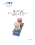
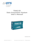
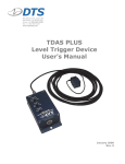
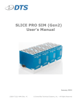
Flex-PLI Quick Start Guide with DTS SLICE October 2015 © Diversified Technical Systems, Inc. - All Rights Reserved Flex-PLI Quick Start Guide with DTS SLICE October 2015 Table of Contents DTS Support ....................................................................................................................... 3 SLICE NANO ....................................................................................................................... 4 SLICEWare .......................................................................................................................... 5 Data Collection Concepts Specific to Flex-PLI Testing .................................................. 5 Circular Buffer Mode ........................................................................................................ 5 Recorder Mode ................................................................................................................ 5 SLICE Flex Integration Kit ................................................................................................. 6 Components required for communication and testing ...................................................... 7 Troubleshooting tools and optional accessories .............................................................. 8 Flex-PLI Special Considerations ....................................................................................... 9 Power Input ...................................................................................................................... 9 System Heating................................................................................................................ 9 Trigger Options ................................................................................................................ 9 Flex-PLI Data Collection .................................................................................................. 10 Test Setup and Data Collection ..................................................................................... 10 Data Download .............................................................................................................. 10 For More Information ....................................................................................................... 11 Appendix A ....................................................................................................................... 12 support.dtsweb.com ii Flex-PLI Quick Start Guide with DTS SLICE Flex-PLI Quick Start Guide with DTS SLICE October 2015 DTS Support DTS systems are designed to be reliable and simple to operate. Should you need assistance, DTS has support engineers worldwide with extensive product knowledge and test experience to help via telephone, e-mail or on-site visits. The best way to contact a DTS support engineer is to submit a request through the DTS Help Center web portal (support.dtsweb.com). You must be registered (support.dtsweb.com/registration) to submit a request (https://support.dtsweb.com/hc/en-us/requests/new). Registration also enables access to additional self-help resources, software and firmware updates, and non-public support information. There is a SLICE Flex-PLI Testing section of the Help Center that can be accessed through the Your Organization tile. Relevant articles and information will be posted there. This guide supports the following products: Flex-PLI support.dtsweb.com 3 Flex-PLI Quick Start Guide with DTS SLICE Flex-PLI Quick Start Guide with DTS SLICE October 2015 SLICE NANO Your Flex-PLI has been integrated with SLICE NANO in a 12- or 24- channel configuration. Check your paperwork for your specific configuration and build information. The SLICE NANO stack in your Flex-PLI functions and can be operated in the same manner as other SLICE MICRO/NANO hardware. Please refer to the SLICE User’s Manual for more information, available on the DTS Help Center. Please refer to the Flex-PLI User Manual and the sensor calibration reports supplied with your Flex-PLI. They contain important information for sensor polarities, recommended SAE filtering and ISO channel names. support.dtsweb.com 4 Flex-PLI Quick Start Guide with DTS SLICE Flex-PLI Quick Start Guide with DTS SLICE October 2015 SLICEWare Getting ready for and collecting data with your Flex-PLI is simple to do with SLICEWare. Please refer to the SLICEWare 1.08 User’s Manual for detailed information on setting up your sensor database, configuring your display, and selecting appropriate test parameters. The SLICEWare User’s Manual is available on the DTS Help Center. Please use the ‘Follow’ feature in the SLICEWare section of the Software tile on the DTS Help Center to be notified of the latest software updates. Data Collection Concepts Specific to Flex-PLI Circular Buffer Mode and Recorder Mode are the two recording modes most commonly used for Flex-PLI testing. Select the appropriate recording mode based on your specific test parameters. DTS recommends verification of all test parameters in a static bench test before performing destructive or dynamic tests. DTS recommends channel zeroing using Average Over Time if there will be a delay between performing diagnostics and data collection. The data zero method and zero window (if applicable) will be determined based on launcher type and specific test parameters. DTS recommends setting the test time window so that the test is complete prior to the SuperCap discharging. Although SLICE writes to flash memory and data is recorded up until power is lost, the time zero maker is not written to memory until after the test is complete. Without the T0, SLICEWare will default to zeroing the channels based on levels measured during diagnostics. Circular Buffer Mode Circular Buffer Mode is advised only when the test length is known and receiving a trigger is certain. DTS recommends using Circular Buffer mode either when using a level trigger or when supplying a T0 signal. A T0 signal can be supplied either through the SLICE Interface Device or through a contact switch connected to the SuperCap leads. Recorder Mode If the test length is unknown or if receiving a T0 signal is uncertain, DTS advises use of Recorder Mode. In this mode, recording can begin before the launcher fires, with a T0 signal being sent some time after. A T0 signal can be supplied either through the SLICE Interface Device or through a contact switch connected to the SuperCap leads. support.dtsweb.com 5 Flex-PLI Quick Start Guide with DTS SLICE Flex-PLI Quick Start Guide with DTS SLICE October 2015 SLICE Flex-PLI Integration Kit The SLICE Flex Integration Kit is available with either USB or Ethernet communication to the control PC. Both Integration kits contain the same items with the exception of the USB/Ethernet Interface Device and associated communication cable(s). Some of the included items are necessary for communication to and testing with your Flex-PLI, and some items are included as troubleshooting aids or for building optional cables. See tables below. support.dtsweb.com 6 Flex-PLI Quick Start Guide with DTS SLICE Flex-PLI Quick Start Guide with DTS SLICE October 2015 Components required for communication and testing Part No Qty Description 13000-30480 1 Quick Release Cable Secure cable to launcher, connect to FlexPLI when mounted on launcher 13000-30550 1 Latching Cable Connect to Flex-PLI for bench/static testing 13000-30430 2 Interface Chain Cable Connects USB/Ethernet Interface Device to latching/quick release cable 13000-30460 1 13000-30490 1 71004-00001 1 71023-00001 1 2 Slice USB Interface Device Connects one SLICE system to PC via USB Slice Ethernet Device Connects one or two SLICE systems to PC via Ethernet 1 USB A to USB B Cable Connects USB Interface Device to PC 1 2 RJ45-RJ45 Ethernet Cable Connects Ethernet Interface Device to PC 10400-00060 1 15 VDC/4A power supply 13000-30800 1 Discharge Plug Used after each test to fully discharge the SuperCap 1 – Only included with USB Integration Kit 2 – Only included with Ethernet Integration Kit support.dtsweb.com 7 Flex-PLI Quick Start Guide with DTS SLICE Flex-PLI Quick Start Guide with DTS SLICE October 2015 Troubleshooting tools and optional accessories Part No Qty Description 13000-30510 1 1-Channel Bridge Plug Use for troubleshooting issues with failed single-channel Bridge channel 13000-30520 1 3-Channel Bridge Plug Use for troubleshooting issues with failed three-channel Bridges 00-01031 1 DB15 connector Use to create a cable for utilizing Status, Start, and Event signals on AUX port 80000-01007 1 DB15 Back shell For use with included DB15 connector if additional Status/Start/Event cable is desired NA USB 2.0 Active Extension Cable Optional accessory cable used to extend distance between PC and test location. Not included with Flex-PLI Integration kit. 13000-30780 support.dtsweb.com 8 Flex-PLI Quick Start Guide with DTS SLICE Flex-PLI Quick Start Guide with DTS SLICE October 2015 Flex-PLI Special Considerations Power Input To avoid damaging the SuperCap and other components of your Flex-PLI DAS, only use the supplied SLICE USB or Ethernet Interface Device. System Heating SLICE NANO is an extremely low power system with minimal self-heating and is isolated from possible temperature sensitive elements in the tibia and femur. However the Flex-PLI is enclosed in layers of neoprene jacketing and it is good practice to not leave the system Armed or in Diagnostics mode for extended periods of time. Trigger (T0) Options • • Level Trigger o Software programmable for any channel, a level trigger will initiate data collection or mark T0 when a predetermined sensor threshold is exceeded. See the SLICEWare User’s Manual for more information on Level Triggering Hardware Trigger o Onboard contact closure through SuperCap Connect a contact closure switch to the exposed leads of the SuperCap to send an Event signal. Note that mounting location and impact point are important factors to consider for test repeatability. o AUX Connector The AUX connector can be used to hardwire a Start Record or Event switch or to monitor the system status. See Appendix A for pinout configurations. o Trigger on disconnect By inverting the trigger polarity in the configuration file it is possible to send an Event signal when the Flex-PLI is disconnected from the UI/EI Chain Cable. support.dtsweb.com 9 Flex-PLI Quick Start Guide with DTS SLICE Flex-PLI Quick Start Guide with DTS SLICE October 2015 Flex-PLI Data Collection Collecting data with your Flex-PLI is very similar to collecting data with your other SLICE systems. The short run time of the SuperCap once disconnected from power requires additional consideration when selecting recording mode and time, and also adds an additional step before data download. The SuperCap should be connected to the USB/Ethernet Interface Device for a minimum of two minutes just prior to each test to ensure it is fully charged. The fully charged SuperCap is capable of powering a 12-channel Flex-PLI for approximately 1 second after disconnect, and a 24-channel system for approximately 0.5 seconds after disconnect. The below steps outline a very basic data collection. The specific details will be determined based on individual test conditions. Test Setup and Data Collection • Refer to the SLICEWare User’s Manual for detailed information on entering sensor information and building the sensor database. • Select the appropriate sampling rate on the Prepare tab and progress through diagnostics to Acquire • Select the Recording Mode and Pre- and Post-Trigger time • Enter Test ID/Notes • Click Arm • Click Stop Monitoring Perform Test Data Download • • • • Connect the Discharge Plug to the Flex-PLI o The LED on the Discharge Plug will illuminate until the SuperCap is fully discharged. DTS recommends leaving the Discharge Plug connected for at least 60 seconds regardless of LED state. o Failure to fully discharge the SuperCap may result in the SLICE NANO stack failing to boot properly. Once the SuperCap is fully discharged, reconnect the Quick Release Cable if preparing for subsequent tests or the Latching Cable if testing is complete Once the SLICE NANO has been rediscovered, click Download ROI/Download All based on test requirements Review and export data as required support.dtsweb.com 10 Flex-PLI Quick Start Guide with DTS SLICE Flex-PLI Quick Start Guide with DTS SLICE October 2015 For More Information SLICE NANO Operation SLICE User’s Manual is available on the DTS Help Center SLICEWare Operation SLICEWare 1.08 User’s Manual is available on the DTS Help Center USB Interface Device See Appendix A Ethernet Interface Device See Appendix A support.dtsweb.com 11 Flex-PLI Quick Start Guide with DTS SLICE Flex-PLI Quick Start Guide with DTS SLICE October 2015 Appendix A support.dtsweb.com 12 Flex-PLI Quick Start Guide with DTS SLICE SLICE USB Interface (UI) The SLICE USB Interface connects 1 SLICE system to a PC via USB. * * Correct input power applied SLICE system is on SLICE system is recording data * You must pull out on the switch before moving—do not force. [email protected] +1 562 493 0158 1 March 2010 ©Diversified Technical Systems, Inc. - All Rights Reserved SLICE USB Interface (UI) SLICE (ECG.2B.312.CLL) 1 2 3 AUX DB15F (high density) 8 9 12 10 11 4 7 6 5 (panel view) Pin 1 6 11 5 10 15 (panel view) Function Pin Function 1 /ON 1 /START, CC to ground 2 /START 2 +Status out 3 /EVENT 3 /EVENT, CC to ground 4 STATUS 6 Ground 5 12.6 VDC out 7 -Status out 6 12.6 VDC out 8 Ground 7 Ground 8 Ground 9 USB power 10 USB_DP 11 USB_DM 12 Ground 15V IN (ECG.2B.304.CLL) This is a standard USB (“B”) interface. A commercial, off-the-shelf USB cable is acceptable. 4 2 3 (panel view) Pin 2 Function 1 +Power (15 VDC) 2 -Power/Ground 3, 4 [email protected] +1 562 493 0158 1 Ground March 2010 ©Diversified Technical Systems, Inc. - All Rights Reserved SLICE Ethernet Interface (EI) The SLICE Ethernet Interface connects 1 or 2 SLICE systems to a PC via Ethernet. * * Input power is over voltage Correct input power applied System boot-up System on All SLICE systems are recording data * You must pull out on the switch before moving—do not force. [email protected] +1 562 493 0158 1 March 2010 ©Diversified Technical Systems, Inc. - All Rights Reserved SLICE Ethernet Interface (EI) SLICE 1 / SLICE 2 (ECG.2B.312.CLL) 1 2 3 AUX DB15F (high density) 8 9 12 10 11 4 7 6 5 (panel view) Pin 1 6 11 5 10 15 (panel view) Function Pin Function 1 /ON 1 /START, CC to ground 2 /START 2 +Status out 3 /EVENT 3 /EVENT, CC to ground 4 STATUS 6 Ground 5 6.5-15 VDC out 7 -Status out 6 6.5-15 VDC out 8 Ground 7 Ground 8 Ground 9 USB power 10 USB_DP 11 USB_DM 12 Ground 15V IN (ECG.2B.304.CLL) This is a standard Ethernet (RJ45) interface. A commercial, off-theshelf patch cable is acceptable. 4 2 3 (panel view) Pin Function 1 +Power (9-15 VDC range) 2 -Power/Ground 3, 4 [email protected] +1 562 493 0158 1 2 Ground March 2010 ©Diversified Technical Systems, Inc. - All Rights Reserved