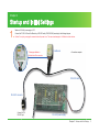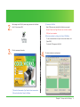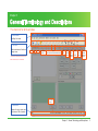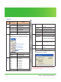
1
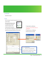
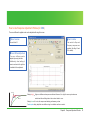
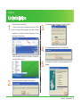
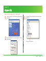
MDUG-CWL/08225E-01 Rev.1
Utility software for Cool Muscle
COOL WORKS LITE
USER'S MANUAL
[ Ver. 4.3.2 ]
INDEX
Chapter 1
Installation
1
Chapter 2
Startup and Initial Settings
3
Chapter 3
General Terminology and Descriptions
5
Chapter 4
Terminal Window
9
Chapter 5
Motor Browser Window
11
Chapter 6
Jog Window
12
Chapter 7
Graph Window
13
Chapter 8
Response Adjustment Window
17
Chapter 9
Uninstallation
23
Chapter 10 Appendix
24
Chapter 1
Installation
CoolWorks Lite
CoolWorks Lite (CWL) is a utility software for CoolMuscle.
CWL can communicate with a CoolMuscle directly. It lets you modify and save
parameters and data. It can jog the motor, plot motor data on a graph and do
Installation
1.
Extract the downloaded zip file.
gain tuning. CWL is CoolMuscle Language (CML) compatible.
CWL is a user-friendly software. It assists in easy operation of CoolMuscle.
Main features
① In the terminal window, data and bank programs can be set and the status
of motion monitored. (Terminal function)
2.
To install, click SETUP.exe in the folder where the files are
extracted.
② In the motor browser window, the motor parameters are easily set. (Motor
browser function)
③ In the Jog window, the motor can be rotated by dragging a slider with the
mouse. (Jog motion function)
④ In the graph window, the position, speed, torque, etc can be displayed
graphically in real time. (Graph function)
⑤ In the Response Adjustment window, controller gain can be easily tuned by
step response or frequency-response. (Response Adjustment function)
The latest CoolWorks Lite can be downloaded for free from the following web
site by answering a simple questionnaire: http://www.musclecorp.com/
Compatible OS: Windows 98 / 2000 / ME / XP
File Size: 2.35MB
*CWL would be updated without notice.
*To install CWL from the CoolMuscle CD, click SETUP.exe in the CD
directly.
Chapter 1 Installation
1
3.
Choose the folder to install CWL according to the instructions given
by the installer. Click [Next] button to continue.
4.
5.
To complete the installation, click [Finish] button.
When the installation is completed successfully, an icon will be
appeared on your desktop.
Chapter 1 Installation
2
Chapter 2
Startup and Initial Settings
1.
Make sure DC+24V power supply is OFF.
Connect the PC, DC+24V and CoolMuscle by a RS-232C cable (CM1C2-2000A) according to the following diagram.
Caution: Do not plug or unplug the connector when the power is on. This can cause damages to CoolMuscle or other devices.
*Please pay attention to
the direction of the connector.
CoolMuscle
< Connection example >
RS-232C cable
RS-232C connector
Connect to PC’s
RS-232C port
DC+24V power supply
Chapter 2 Startup and Initial Settings
3
2.
③ Choose the COM Port.
After turning on the DC+24V power supply, double click CoolWorks
Enter COM port number which the CoolMuscle is connected.
Lite 4.3.2 icon to open CWL.
Remark: Please refer Page 22 about how to find the available
COM port in your computer.
④ Start communication by clicking on the [Open COM] Button.
To start communication and open the terminal window, click
[Open COM].
To close the CWL program, click [Exit].
3.
Fill in the necessary information:
4.
The terminal window is now displayed.
①
②
③
④
① Choose the Communication Type. Default is Serial communication.
② Choose the Baud Rate. Default is 38400bps.
Chapter 2 Startup and Initial Settings
4
Chapter 3
General Terminology and Descriptions
The menu bar for all the windows
① Main Menu
See Page 6 for details.
② Tool bar
Select windows and functions
through icons.
Cut
Copy
Paste
Communication
settings
Open
COM1/COM2/COM3/COM4/COM5/COM6
* Response adjustment window will not
Close
COM
Open
terminal
window
Open
motor
browser
window
Open
jog
window
Open
graph
window
Open
Response
adjustment
window *
work for Ver 3.00 and 1.07 or before.
Motor firmware
version
③ Status bar
Displays the motor status and
other relevant CWL information.
Chapter 3 General Terminology and Descriptions
5
① Menu bar
Menu
File
Edit
View
Name of Item
Description
Open
Open a selected file into the CML Editor
Exit
Close CoolWorks Lite
Undo
Undo of the last action
Cut
Cut the selected area
Copy
Copy the selected area to the clipboard
Paste
Paste the contents on the clipboard
CM Toolbox :
Display the CM toolbox on the upper left corner of the screen
Windows
Tools
Choose the motor ID
Stop the motor
Options
Enable the motor
Disable the motor
Help
Toolbar
Status Bar
Language
Communi- COM1
Set Show/Hide toolbar
Set Show/Hide Status bar
Set the language for CWL
Open COM port 1
cation
COM2
COM3
Open COM port 2
Open COM port 3
COM4
COM5
COM6
Close
Open COM port 4
Open COM port 5
Open COM port 6
Terminate communication
*1
Terminal
Display the terminal window
(main window)
Motor Browser
Display the motor browser window
Jog
Display the jog window
Graph
Display the graph window
Response Adjustment *1 Display the response adjustment window
Speed Calculator *2
Convert the speed value from rpm to pps
Motion Calculator *3
Calculate the motion data according to
given position, speed, acceleration and
time
Copy Motor Settings *4 Copy the settings from one motor to the
other
Data Log *5
Record the log file of incoming messages
from motors
Contents
About CoolWorks Lite : The version information for CoolWorks
Lite is displayed in the following window
The Response Adjustment window cannot be used for firmware Ver. 1.07 or before.
*2-5 Please refer to page 7-8 for the details.
Chapter 3 General Terminology and Descriptions
6
*2
Speed Calculator
*3
Motion Calculator
① Enter the target speed in rpm.
① Set motion type. ② Set the combination of resolution and speed unit. ③
② Click [Calculate] button.
Choose distance, speed, acceleration or time to be calculated. ④ Enter the
③ Calculate the Speed value in pps for given resolution.
necessary data for calculation.
* Since the incremental motion can not be executed when K37=40s
and 60s (Except for K37=41 and 61), the speed calculator does not
show the resolutions for K37=40s and 60s.
①
⑥ The chosen
variable and time for motion will be calculated.
②
①
③
In the left case, distance of
Rotation type is selected.
Resolution = 1000ppr.
②
③
⑤ Click [Calculate] button.
Speed unit = 100pps.
Speed=10000(100*100)pps,
④
⑤
Acceleration=100kpps2 and
⑥
Time = 10s.
The rotation distance is
calculated as 99000 pulses.
To transform the result to the
other motion type (in this case
it is Linear type), simply change
the motion type. You will have to
For the above case where the Resolution is 1000ppr and Speed Unit is
enter the pitch data first.
100pps, s=167 is calculated as 1002rpm.
* Enter the pitch data in the Linear type.
Chapter 3 General Terminology and Descriptions
7
*4
Copy Motor Settings
*5
Data Log
Copy the motor parameters and program banks from one motor to the other.
To record the incoming messages from the motors, check [Log file on].
Caution: The settings for the motor depend on its type. Such as 23L, 17S,
*The [Log file on] is not checked by default.
C type and P type. Please be careful when copying between motors with
The log file will be reset if [Log file on] is unchecked or CWL is closed.
different types.
① Select the source motor ID. To read the data, click [Read] button.
② Select the destination motor ID. To copy the motor settings, click [Copy]
Display the log file
Send the log file by Email
button.
Chapter 3 General Terminology and Descriptions
8
Chapter 4
Ter minal Window
How to Use Terminal Window
The first window displayed after opening CWL and selecting a COM port is the terminal window.
The terminal window allows reading and writing of motor data, parameters and program banks.
Text files created in other editors, for example, notepad, can be read into this window. It is convenient to save data as a file and use it later repeatedly.
⑤ Motor ID
Select the target motor ID.
① Command Line
Enter CML commands in a single line
⑥ Function Buttons
and press [Enter] key to send.
Go to origin. Reset motor coordinates
and motor Enable / Disable.
② CML Editor
⑦ Motor data
Send multiple lines of CML at the same
See Page 10 for details.
time. To send a set of commands click
[Send] button.
⑧ Motor information
See Page 10 for details.
③ Sent Data
Display the data sent to the motor in ①
⑨ Buttons for Program bank
or ② . To clear the motor response
See Page 10 for details.
window click [Clear] button.
⑩ Motor Response
④ Save / Print / Email
Save / Print / Email the data which is
sent to or received from motors.
Display the data received from the motor.
To clear the Motor Response window
click [Clear] button.
The data log file will not be affected by
clicking [Clear] button.
Chapter 4 Terminal Window
9
⑨ Buttons for Program bank
⑦ Motor data
B u t t on
Query
?91
Description
Button
Command
Description
Display the list of position data
Choose bank No. from the list (1-30)
?93
Display the list of acceleration data
?92
Display the list of speed data
?94
Display the list of timer data
?90
?
<.1
Execute previous line of a bank
[m.1
[m.1 Execute bank m in motor 1
].1 ].1
Stop bank execution
}.1 }.1
Stop bank execution after current motion
Display the list of K parameters
Display the data for direct mode motion
⑧ Motor information
B u t t on
Query
].1
Pause bank execution
}.1
Pause bank execution after current motion
>.1
Execute the next line of a bank
Description
?99
Display current motor status
?98
Display current motor torque
?96
Display current motor position
?95
Display current position error
?97
Display current motor speed
?m.1
* m is selected from the Bank No. list.
Display bank m in motor 1
* ID1 must be selected in ⑤ Motor ID.
Chapter 4 Terminal Window
10
Chapter 5
Motor Browser Window
How to Use Motor Browser Window
Motor data and parameters can be set up by features.
① Open the feature folder which you want to check or change. ② The list of parameters related to this feature are displayed in the right window. Choose and double
click the parameter that you want to modify. ③ The setting window of the parameter is displayed. ④ In order to change the data, choose an item from the data list or
⑤ enter data directly and then click [OK]. *At this point, the modified data has not been sent to the motor.
After modifying all the data, click ⑦ [Apply All] or ⑧ [Apply]. ⑨ A dialog box is displayed. To save the data to the motor, click [OK]. To save the parameters to the
PC, click ⑥ [Save To File]. *Only parameters can be saved in PC.
Enter a number directly when using a combination of
functions as K23.
①
This example shows "7" should be entered to assign
"1: In-position and Alarm", "2: Report when input
signal changes" and "4: Report when output signal
changes" as 1 + 2 + 4 = 7.
②
③
⑤
④
* It takes several seconds to read
the data from the motor when the
⑨
motor browser is started up.
Please wait until the status bar
changes from [Reading data from
motor!] to [Ready].
Save the parameters
to the PC.
⑥
Save the data to all
the motors connected.
⑦
Save the data to the
current selected motor.
⑧
Caution: If you click [OK], the original
data of the motor will be changed.
Chapter 5 Motor Browser Window
11
Chapter 6
Jog Window
How to Use Jog Window
This window is for a jog motion with the mouse pointer. The resolution and speed unit can be set.
For jog motion, click and drag the slider on the speed bar. The resolution changed in this window will be saved to the motor.
* Any modification of the resolution and speed unit will be saved to the motor. The current position is displayed according to the modified resolution.
Choose Speed unit
100pps or 10pps
Choose Resolution
from 200-50000 ppr
* Since the incremental motion can
not be executed when K37=40s
and 60s (Except for K37=41 and
61), this list does not show the
resolutions for K37=40s and 60s.
Move to the position 0
Chapter 6 Jog Window
12
Chapter 7
Caution: Do not start-up the Graph Window function while Cool Muscle is not
powered on or executing communication frequently.
Doing so may cause CWL to stop working and to be inoperative subsequently.
To recover from such unusual situation, the reinstall of CWL is necessary.
Graph Window
How to Use Graph Window
① Graph Prop
Set the necessary data. (See Page 14 for details)
The specified data can be displayed in a graph. Operate according to steps from ①~⑪ .
② Clear Graph Clear graphical data displayed.
③ Setting
Choose Streaming for Ver 2.20 or after.
Choose Polling for Ver1.07 or before.
④ Sampling Time (unit: msec)
The sampling time for data streaming or polling. (1-30000)
⑥
⑤ Plot Type (See Page 15 and 16 for details)
[Time History Plot]: Display the data trend versus time.
[X-Y Plot]: Display two related data in an X-Y plane.
Choose one of the two.
* When only one motor is connected, [ X-Y Plot ] is not displayed.
⑥ CML Data
Please enter the motion commands in this window which will be
used for generating the graph. Any direct motion commands or
bank programs are available.
* When only one motor is
connected, [ X-Y Plot ] is
not displayed.
③
①
②
④
⑤
⑪
Run the motor according to the CML data given.
⑦ Run
Stop the motion.
⑧ Stop
Draw the graph.
⑨ Draw
⑩ Stop Draw Stop drawing the graph.
⑪ Data Selection
⑦
⑨
⑧
⑩
To select the data for monitoring, first select the motor ID from
[Motor ID] and then select data type from [Data Type] for each
motor.
Streaming
Polling
0: No Action
1: Target Speed
2: Real Position
3: Real Speed
4: Torque
0: No Action
1: Real Position
2: Real Speed
3: Torque
4: Position Error
Chapter 7 Graph Window
13
① Setting of Graph Properties
To display the following window, click [Graph prop] button.
Set the minimum and
maximum values for the X
axis (an integer between
-32767 and 32767).
Set the minimum and
maximum values for the Y
axis (an integer between
-32767 and 32767).
Set the horizontal and
vertical grid numbers (an
i n t e g e r b et we e n 1 a n d
32767).
Set the labels for the X
axis, Y axis and title.
The color of each data
line can be independently
defined.
Set the Background Color,
Grid Color and Font.
Set the width of the line
and the scale of the data.
Chapter 7 Graph Window
14
④ Plot Type [ Time History Plot ]
The time history plot, data (Y axis) can be displayed versus time (X axis). Unit for the X axis is SamplingTime (msec).
*When multiple motors are selected, graphs will be displayed only when the motor of the final axis is in motion.
Even when multiple motors are connected, the data
from specified motors can be obtained by setting
unspecified motor's Data Type as [ 0: No Action ].
Chapter 7 Graph Window
15
④ Plot Type [ X-Y Plot ]
* When only one motor is connected, [ X-Y Plot ] is not displayed.
Related data will be displayed in X-Y plane. (The following example is real time position display)
*When multiple motors are selected, graphs will be displayed only when the motor of the final axis is in motion.
Chapter 7 Graph Window
16
Chapter 8
Caution: Motor will vibrate during the identification and tuning process.
Response Adjustment Window
* This window will not work for Ver 3.00 and 1.07 or before.
* It is not auto tuning.
Type of Response Adjustment Window
The screen contiguration depends on Cool Muscle's version.
For CM1 (ver.2.XX)
Tuning and simulation are available. (See Page 18 21 for details)
For CM2 (ver.3.XX)
Servo stiffness adjustment is available. (See Page 22 for details)
Chapter 8 Response Adjustment Window
17
How to Use Response Adjustment Window (for CM1)
The Response Adjustment window can simulate and assist tuning the PPI control parameters.
① Motor Selection
③ Control Design and Simulation
Position P Gain, Speed P and I
Choose Motor ID and Motor Type.
①
② Identify System Inertia (Optional)
②
③
④
Gain can be tuned by comparing the
results of the simulation for a given
Calculate and display the inertia of
inertia and viscosity coefficient.
the payload by experimental results
(See Page 18 for details)
based on the vibration starting
from [Starting Freq] to [Ending
④ Test Controller
Freq] with the given Amplitude.
Test results for Step and Frequency
(See Page 18 for details)
responses are available.
(See Page 19 and 20 for details)
The tuning result is dependent on the payload inertia. ② Identify System Inertia is a tool to identify the payload inertia when the design value is unknown. All the
conditions for identification must be set properly in order to get an accurate estimation. The identification results might be different if the experimental conditions are
not set properly. The estimated result might not be accurate enough even under the proper experimental condition. The estimated data is a reference to adjust the
tuning. The parameters must be tuned with a trial motion. ③ Control Design and Simulation: Simulate with different inertia. If the inertia of payload is unknown use
the inertia identification function.
[Identification] is to add some probing signal to the system and estimate the unknown parameter of it in order to build a mathematical model for control design.
Chapter 8 Response Adjustment Window
18
[ Identification Error ]
② Identify System Inertia
Identify the inertia of the playload by motor's information from vibration at
The identification error will be occurred when the identification results do not converge
which is tested at each frequency.
specified frequency. Precise identification is achieved by aggregating the
When the identification error occurs the data shall be reflected but the identification result
information from the motor by gradually increasing the vibration frequency.
shall be considered as inadequate. More precise identification result will be obtained by
The amplitude pulse setting shall always be based on 50000ppr despite the
avoiding errors following the steps below.
Step 1. Increase the value for Max Iq (torque)
motor's set resolution.
Ex) The motor shaft will vibrate between plus minus 3.6 degrees
(500pulses/50000ppr) when the amplitude pulse is set to 500.
① Enter the Starting frequency, Ending frequency, Amplitude and Max Iq.
(Set these values according to your machine)
② To start the identification, click [Start Iden.] button.
*The altitude of the vibration increases gradually during the identification process.
Pay attention please.
Motor Type
Max Iq (Torque)
11S
40
11L
50
17S
50
17L
90
23S
140
23L
150
If the identification error can not be avoided
Step 2. Decrease the value for amplitude pulse (pulse)
If the identification error can not be avoided
Step 3. Increase the value for ending frequency(Hz)
③ Control Design and Simulation
① Enter the inertia directly if it is known. If the inertia is already known and
entered into this box, previous step is not necessary.
② Enter the viscosity coefficient if it is known. If it is unknown, enter 0.
③ Tuning of Position P Gain, Speed P Gain and Speed I Gain.
Click and drag the slider on one of the bars. The simulation result is
displayed in the graph. Tune the gains refering to the simulation results.
The gain values can be entered directly, however the results is displayed
only after the click of [Start] button in ④ .
③ To stop the identification, click [STOP].
④ When identification ends, click [OK].
The value, subtracted the rotor inertia from
the identified result, will be entered into Load
Inertia box in ③ .
* The data is not sent to the motor yet at this point.
④ Set the inertia for simulation to the same value as the normal payload.
However, you can set it to any value for the simulation.
⑤ To send the tuned gains to the motor, click [Send to Motor] button.
*The data will be sent to the motor.
Chapter 8 Response Adjustment Window
19
④ Test Controller
Select Step Test or Freq Test.
[Step Test]
Step Test is as shown in the right, the output waveform when step shaped
command is entered.
Step response test has the feature that shows
the characteristic features intuitively and
comprehensibly. Roughness could be
① To start the Step Test, click [Start] button.
still existing instead of the above features.
* The motor will move 7.2 degree instantaneously during the test.
Step command 1000pulse / 50000ppr that is 7.2 degree on the motor shaft
is applied for the step response test despite the motor's set resolution.
Pay attention please.
② To stop the test process, click [Stop] button.
③ When the test process ends, click [OK].
Red line = The simulation result from ③
Green line = Real response for the same experimental condition
The step response is displayed. The experimental data is also displayed in
[The instruction] box for every 2msec (1000pulse = 7.2 degree).
Chapter 8 Response Adjustment Window
20
[Frequency Test]
Frequency response shows output gain(amplitude proportion) against input
frequency command.
Gain (dB) shall be 20log10K and the output amplitude proportion against
input shall be K time. When gain equals 0, the amplitude proportion equals 1.
So that the same output amplitude as input amplitude shall be obtained.
Frequency characteristic has features as less intuition but minutia feature is
well described.
Frequency response test displays its response characteristic by increasing
① To start the Frequency Test, click [Start] button.
the amplitude 3.6 degree (500pulse / 50000ppr) sine wave from 1(Hz) up to
* The motor shaft will vibrate in the range of plus minus 3.6 degrees then
100(Hz) despite the motor's set resolution.
the frequency of vibration will be increased gradually.
Pay attention please.
② To stop the test process, click [Stop] button.
③ When the test process ends, click [OK].
X axis in frequency response graph is an angular frequency ω (rad/sec)
and the formula in relation with the frequency f is ω (rad/sec) = 2 π f
Ex) When 100(Hz), 2 ×π × 100 ≒ 628(rad/sec)
Chapter 8 Response Adjustment Window
21
How to Use Response Adjustment Window (for CM2)
The servo stiffness for applied motor can be adjusted with using this screen.
Motor Selection
Test Controller
Test results for Step and
Choose Motor ID .
①
Frequency responses are
③
available. (See Page 19 and
②
20 for details)
Servo Stiffness Adjustment
The servo stiffness can be
adjusted by moving the slider.
Additionally, direct setting of
numeric number into the right box
is available for the adjustment.
Overshoot
Setting is high
Adequate
High servo stiffness and response are obtained. However, if too high, the servo system becomes
unstable and the oscillating state or the overshoot tends to occur.
Too low
Setting is low
If too low, the response and tracking performance go down.
For adequate setting, adjust the servo stiffness to get no oscillation and less overshoot.
Chapter 8 Response Adjustment Window
22
Chapter 9
Uninstallation
1.
There are two ways to uninstall CWL.
① Open the control panel for windows on the start menu. Click
the icon for Change or Remove programs. Select [Add or Remove
3.
The following message will be displayed. Click [Yes To All] button.
Programs] icon on the left column. Select CoolWorks Lite 4.3.2 and
click [Change / Remove] button.
4.
The following message will be displayed. Click [Yes] button.
5.
The uninstallation is successful if the following message window is
② Select the shortcut in start menu / All Programs / CoolWorks Lite
/ unInstall CoolWorks Lite 4.3.2.
2.
displayed.
The following message will be displayed. Click [Yes] button.
Chapter 9 Uninstallation
23
Chapter 10
Appendix
How to find the COM port No. in Window XP
1.
2.
Open the Control panel, click [Performance and Maintenance] and
then [System].
3.
The available COM ports are displayed in the tree selection [Ports
(COM & LPT)] .
Choose [Hardware] Tab on the opened window and then click
[Device Manager].
In this case, COM1 is available.
Chapter 10 Appendix
24
http://www.musclecorp.com/
*Microsoft and Windows are registered trademarks of Microsoft Corporation in the United States and other countries.
*Other company names and product names described in this document are trademarks or registered trademarks of their respective holders.
*The trademarks notices (™, ®) are not necessarily appended to company, system, and product names described in this document.
© 2007 Muscle Corporation. All rights reserved.