1
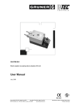
User Manual - GA-P70-024
Page 4
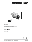
Direct coupled, non-spring return actuators, 70 in-lb
1
Application
Actuators to be easily installed by direct shaft mounting on air dampers, shutters and butterfly valves in
ventilation and air conditioning systems. Can be controlled by any compatible electric or electronic analog
controller DDC/PLC control or automation system. The actuators should be mounted indoors in a dry environment, relatively free from corrosive fumes.
2
Safety remarks
The actuators are not suitable for use in explosive atmospheric applications!
All service to the actuators (mounting, electrical connection, retrofitting and repair) must be carried out with the
power supply disconnected. The electrical connection must be done by a trained and competent person considering the wiring diagrams, local and national regulations. Use copper twisted conductors only. Provide disconnect and overload protection if necessary.
This actuator may only be operated by 24 VAC/VDC!
The transformer must be sized according to technical data of the actuator (see section 10). Electronics and
controllers must be powered from a separate transformer when controller power is full-wave rectified. Otherwise
the controller or the actuator may be damaged.
Always read the controller installation instructions before making any connection!
3
Installation
Direct mounting with V-bolt clamp to the damper shaft (diagr. 1) and fixing with enclosed anti-rotation
mounting bracket (diagr. 2).
Shaft: Ø 5/16" to 5/8" (Ø 8 - 16 mm)
5/16" to 15/32" ( 8 - 12 mm)
•
•
•
Turn the damper until the blades are closed
Disengage the gears by pressing the red button and rotate the clamp until the switching position
indication shows 90°
Tighten the nuts on the clamp (4 - 6 ft-lb)
diagram 1
Customer Services (858) 578-7887 & (888) GO INTEC
Fax (858) 578-4633 & (888) FX INTEC
www.inteccontrols.com
INTEC Controls, 12700 Stowe Dr., Suite 100, Poway, CA 92064
diagram 2
Specification subject to change without notice.
Printed in Germany