1
Communication via CAN bus (CANopen)
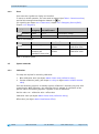
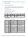
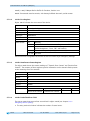
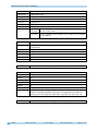
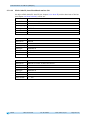
The transfer behavior of RPDO1 is defined via objects 1400h and 1600h. RPDO2 is defined via
objects 1401h and 1601h.
A differentiation is made between Setpoint1 und Setpoint2 only in the alpha-numeric display
mode. Setpoint1 is displayed in the upper row and Setpoint2 in the lower row. In the
position-dependent modes, the setpoint last received, if valid, is output in the 2nd row.
5.3.2
Control word
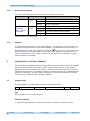
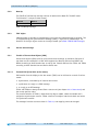
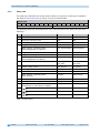
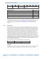
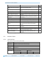
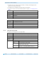
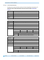
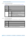
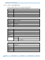
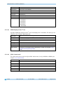
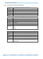
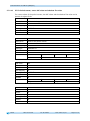
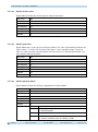
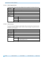
The control word consists of 16 bits and is mapped in the object 5F0Ch: Control word. This
object is received with both Receive PDOs.
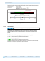
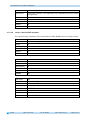
Control word
15 14 13 12 11
MSB
High Byte
10
9
8
7
6
5
4
Low Byte
3
2
1
0
LSB
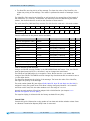
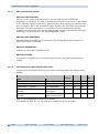
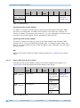
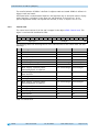
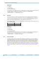
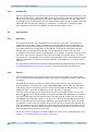
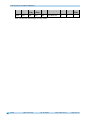
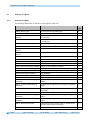
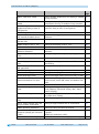
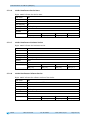
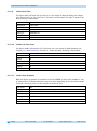
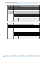
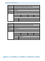
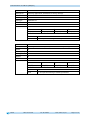
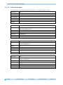
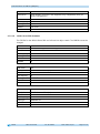
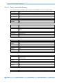
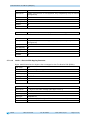
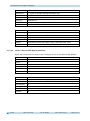
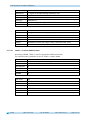
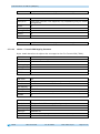
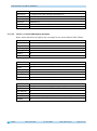
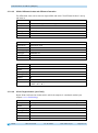
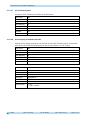
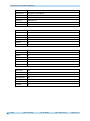
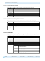
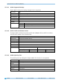
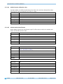
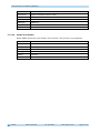
The following table lists the designations of the individual bits of the control word and their
meanings.
Bit
0
1
2
3
4
5
6
7
8
9
10
11
12
13
14
15
Meaning
reserved
reserved
Validity of setpoint1
Display range
Acknowledgment target window1 static
reserved
With "Display" operating mode:
Acknowledgement of setpoint2
With "Display" operating mode:
Data identifier
Guarding Bit
Validity of setpoint2
With "Display" operating mode:
Acknowledgement of setpoint1
LED1 green left
LED3 green right
LED4 red right
LED2 red left
LED blinking
Value = 0
ever 0
ever 0
invalid
standard
not acknowledged
ever 0
not acknowledged
Value = 1
valid
extended
acknowledged
acknowledged
number
ASCII
is taken over
invalid
not acknowledged
is taken over
valid
acknowledged
Off
Off
Off
Off
Off
On
On
On
On
On
Table 14: Control word
AP10
Date: 07.04.2015
Art. No. 86853
Mod. status 132/15
Page 21 of 77