1
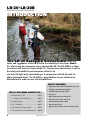
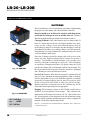
Since 1964, the leader in effective, safe and reliable products for fisheries conservation.
Knowledgeable biologists depend upon Smith-Root equipment.
USER'S MANUAL
LR-20B
SMITH-ROOT, INC.
Includes model
LR-20 (200w)
Products for Fisheries Conservation
WWW.SMITH-ROOT.COM
09441.04
USER'S MANUAL
LR-20B Backpack Electrofisher
Operation and maintenance
Contents
Introduction....................................................................... 1
Overview............................................................................ 2
Controls & Connectors..................................................... 4
Packframe.......................................................................... 6
Cable Strain Relief Clips.................................................. 7
Operation........................................................................... 8
Safety Features.................................................................. 9
Electrofishing Safety....................................................... 11
Battery Care & Maintenance......................................... 13
Battery Maintenance & Diagnostic equipment............ 19
Electrode Pole Testing..................................................... 20
Cathode Testing............................................................... 21
Electrode/Cathode Tester............................................... 21
LR-20B Operation Hints................................................ 22
Cleaning & Maintenance................................................ 22
Model 12/15 Settings Chart............................................ 23
Specifications................................................................... 24
Items manufactured by companies other than Smith-Root carry the original manufacturer’s warranty. Please contact
product manufacturer for return instructions.
All Smith-Root, Inc. manufactured products are covered by a one-year warranty.
Credit & Refund Policy: Customers returning equipment, in new condition, will be given credit within five days from the date of the return. A return
authorization must accompany returns. Valid equipment returns include, but are not limited to, ordering incorrect equipment, funding deficits, and defective
equipment returned for reimbursement. All returns are subject to a restocking fee and applicable shipping charges. The restocking fee is figured at 10% of
the purchase price but not less than $20.00. Customers receiving equipment in damaged condition will be referred to the shipping company for insurance
reimbursement.
09441.04, © 2012 Smith-Root, Inc. Vancouver, WA - USA •
2011
I
LR-20
LR-20B
BACKPACK ELECTROFISHER
&
Introduction
The LR-20 Backpack Electrofisher offers the
safety and ruggedness of the LR-24 with the reliability of our classic Model
12, while using the accessories of our standard LR-24. The LR-20B is an ideal
transitional unit from our classic Model 12; it shares many conventions as well as
the safety and reliability and accessories of the LR-24.
Use them for light-duty electrofishing or in conjunction with LR-24 units for
wider field applications. The LR-20B is a good addition to your collection of
Electrofishers in order to cover all field conditions.
SAFETY FEATURES:
• Emergency shut-down switch disables the unit
• Flashing red output warning light
THE LR-20B Combo Consists of:
1 - Electrode Pole 6' 2PC................................07575
• Tilt sensor
• Water immersion turns output off
1 - 11" Aluminum Electrode Ring...................03297
• Electrode out of water output off
1 - Rattail Electrode........................................06821
• Pole mounted operator switch
2 - 24V 7 Ah Battery......................................06681
• Non-conductive case
1 - UBC-24 Battery Charger (USA).................06815
• Quick release shoulder harness and waist belt
1 - Case w/Wheels & Retractable Handle.......09540
1
• Audible output warning system
www.smith-root.com
USER'S MANUAL
Overview
Controls and Features
Take the time to familiarize yourself with the LR-20's features before beginning electrofishing.
Timer Reset
Pack Frame
Duty Cycle
Output Frequency
Cover Latch
Emergency
Shutdown
Switch
Lcd Display
Voltage Range
Switch
Audio Alarm
Warning Light
Cover Latch
Sensor
Immersion
Sensor
Harness
Cathode
Connector
Anode
Connector
24v Battery
Control
Connector
Battery Connector
2011
2
LR-20
LR-20B
BACKPACK ELECTROFISHER
&
OVERVIEW (Cont.)
Output Frequency- controls the output frequency or
pulses per second of the electrofisher.
V
O
L
T
S
Duty Cycle- Controls the percentage of time the output
pulse is on out of the time from the start of one output pulse to
the start of the next output pulse.
DUTY
CYCLE
Timer Reset- Resets the seconds counter display to zero.
FREQUENCY
LCD Display- Shows the number of seconds the output
of the unit has been active since the last timer reset, the peak
output voltage and current, the average battery voltage and
current, a fuel gauge type display of the battery voltage, heatsink temperature and waveform settings.
Duty cycle and Output Frequency
V
O
L
T
S
DUTY
CYCLE
Audio Alarm- Provides loud audio warning whenever 30
volts or more are present between the anode and cathode and
also when the unit is first switched on.
PERIOD
OUTPUT CONTROL
40
35
30
25
20
45 50 60
35 40 45
70
50
30
80 25
60
90 20
70
100 15
80
2 PULSES
110
10
15 10 120
3 PULSES
5
DC GATED BURST
FREQUENCY
Warning Light- Flashes once per second whenever 30
volts or more are present between the anode and cathode and
TIMER
also when the unit is first switched on.
PUSH
Emergency Shutdown Switch- Turns unit on
when the red cover and switch are in the up position. Also
serves as an emergency shutdown switch by means of red flipdown cover.
TO RESET
DUTY CYCLE
Clockwise: LCD display; Power/
Emergency Shutdown Switch;
Output Frequency and Duty
Cycle switches; Cover Latch.
LR-20 Electrofisher
v.0.22
Smith-Root, Inc.
www.smith-root.com
Voltage Range Switch- Controls the output voltage
of the
VOLTAGE
RANGE electrofisher. Voltages between 50 and 990 volts may be
selected.
250
0
25
2 00
500
100
700
400
500
700
990 990
LR-20
Anode
Connector - Provides the high voltage
connection for the anode electrode.
Backpack
Electrofisher
ATTENTION: FRONT COVER MUST BE CLOSED FOR UNIT TO OPERATE
Left to right: Cathode connector;
power cord; control connector;
anode connector.
3
50
350
500
50 50
Control Anode
350
400
Immersion Sensor - Automatically turns the output off
when water bridges the sensing contacts.
0
10
100
300
300 35
0
70
0
150
150
CATHODE
300
150
400
200
Cathode Power
250
200
ANODE
Connector- Provides the low voltage control
Control
connection to the pole switch.
CONTROL
Cathode Connector- Provides the high voltage
connection to the cathode electrode.
Battery Connector- Provides power to the unit from
the battery.
Cover Latch and sensor- Two over-center toggle
latches secure the front cover. Cover must be closed and
latched before the output of the unit can be activated.
www.smith-root.com
990
USER'S MANUAL
Controls & Connectors
External Controls, Connectors and Sensors
ON/OFF SWITCH: Located on the right side of the
electrofisher under the red emergency off cover. To turn
the unit on, raise the cover and push the switch up to the
on position. To turn the unit off, press down on the red
emergency off cover.
ANODE CONNECTOR: Located on the bottom right
corner of the electrofisher the large black 2 socket connector
provides the high voltage connection for the anode electrode.
This connector has a locating lug that assures the anode pole
can only be connected one way. The proper connection for
the anode pole is with the cable pointing away from the
backpack.
BATTERY POWER CONNECTOR: Located on the
bottom left center of the electrofisher this red and black color
coded connector provides power to the unit from the battery*.
To connect a battery to the electrofisher, match the colors on
the battery connector to the colors on the battery's connector,
red to red and black to black**.
* C A U T I O N : Before connecting or
disconnecting a battery to the unit, make
sure the power switch is in the off position,
failure to do so may cause damage to the battery and the
electrofisher.
**WARNING: Reversing the connectors
will damage the electrofisher and may cause
serious injury or death.
CATHODE CONNECTOR: Located on the bottom left
corner of the electrofisher the large black 2-socket connector
provides the high voltage connection to the cathode electrode.
This connector has a locating lug that assures the cathode can
only be connected one way. The proper connection for the
cathode is with the cable pointing away from the backpack.
CONTROL CONNECTOR: Located on the bottom right
center of the electrofisher the small black 4-socket connector
provides the low voltage control connection to the pole
switch. This connector has a locating lug that assures that
the control connector can only be connected one way. The
proper connection for the control connector is with the cable
pointing away from the backpack.
IMMERSION SENSOR: Located on the bottom left
corner of the enclosure behind the cathode connector. The
output of the electrofisher is automatically deactivated when
these contacts come in contact with water.
NOTE: Although the immersion sensor is located above the
battery tray of the LR-20, do not submerge the battery; doing
so will cause damage to the battery and the electrofisher.
FRONT COVER: The clear window cover of the control
panel allows easy observation of the controls and display. To
open the cover, release the over-center latches at the top and
bottom right corners of the electrofisher.
NOTE: The front cover must be closed and latched
before the output of the unit can be activated.
2011
4
LR-20
LR-20B
BACKPACK ELECTROFISHER
&
CONTROLS & CONNECTORS (Cont.)
Front Panel Controls and Indicators
TIMER RESET: Located on the upper right corner of the
front panel. This switch allows the user to reset the 6 digit
seconds timer back to 0.
OUTPUT CONTROL
FREQUENCY
DUTY CYCLE
70
30
80 25
90 20
100 15
110
10
15 10 120
5
DC
50
60
70
80
2 PULSES
3 PULSES
PUSH
TO RESET
GATED BURST
LR-20 Electrofisher
v.0.22
Smith-Root, Inc.
www.smith-root.com
Frequency: Located on the upper left of the front panel.
This switch controls the output frequency or pulses per second
of the electrofisher. When the duty cycle switch is set to DC,
Gated Burst 2 pulse or Gated Burst 3 pulse, this switch has no
effect on the output of the electrofisher.
VOLTAGE RANGE
500
2 00
400
250 300 350
2000 300 35
400
0 500
150 25
100
700
50
990
0
10
70
0
150
Display: Located in the top center of the front panel. The
display shows the number of seconds the output of the LR-20
has been active since the last timer reset, the output voltage and
current and a fuel gauge type display of the battery voltage.
The backlight of the LCD display is always on when the
electrofisher is on; this allows easy viewing of the display even
in deep shadows without the need to open the front cover and
turn on another switch.
35 40 45
40
35
30
25
20
Duty Cycle: Located on the upper left center of the front
panel. This switch controls the percentage of time the output
pulse is on out of the time from the start of one output pulse to
the start of the next output pulse. When the duty cycle is set to
DC, the electrofisher puts out a constant DC voltage determined
by the voltage range switch.
TIMER
45 50 60
50
9 90
Backpack
LR-20 Electrofisher
ATTENTION: FRONT COVER MUST BE CLOSED FOR UNIT TO OPERATE
CATHODE
CONTROL
ANODE
LR-20/LR-20B FRONT PANEL - Top to bottom,
left to right: Frequency, Duty Cycle knobs; Timer Reset
Button; Display Window; Voltage Range Switch; Audio
Alarm; Warning Light.
Voltage Range Switch: Located on the left side of
the front panel. This 11-position switch controls the output voltage of the electrofisher. Voltages between 50 and 990 volts
may be selected.
Warning Light: Located in the bottom center of the front panel. Wide viewing angle, high brightness red LED's flash
once per second whenever 30 volts or more are present between the anode and cathode and also when the unit is first switched
on.
Audio Alarm: Located on the right side of the front panel. A high volume audio alarm with volume shutters provides
additional warning whenever 30 volts or more are present between the anode and cathode. In addition, the beep rate gives an
indication of the power being drawn by the unit. It also sounds when the unit is first switched on.
5
www.smith-root.com
USER'S MANUAL
BATTERY INSTALLATION
BATTERY INSTALLATION AND SAFETY
BATTERY INSTALLATION
To ensure operator and unit safety, as well as the life of the battery,
care must be taken to make sure that the battery is installed
correctly.
The easiest way to install the battery is to place the electrofisher
on the ground (or similar safe, dry surface), rather than on the
operator's back.
A.Start by placing the LR-20B on the ground, orienting the
battery inside with its bottom on the wall towards the
packframe and centering it towards the bottom.
B.Lay the battery inside the battery tray handle up, so that the
power connectors are closest to the control box.
C.The handle should fit inside the corresponding notch in the
front of the tray.
Pass the battery strap through the oval handle cutout and secure
the clasp while taking up any slack in the strap. It should be snug
and not allow the battery to move.
2011
6
LR-20
LR-20B
BACKPACK ELECTROFISHER
&
PACKFRAME
Packframe
The packframe allows for various positions of the shoulder straps and waist belt to fit most people. The straps and belt
all have quick release latches that allow the Electrofisher to be removed quickly if the operator falls into deep water or
becomes injured*.
Shoulder Strap
Adjustment
Shoulder Strap
Chest Strap Quick
Release
Padded Waist Belt
Pack Frame
Waist Belt Quick
Release
*WARNING: Always unfasten the chest strap of the pack before crossing or entering the
water. Should you fall into deep water, the chest strap may prevent you from removing the
electrofisher quickly.
7
www.smith-root.com
USER'S MANUAL
QUICK RELEASE
PACKFRAME QUICK RELEASE - STRAIN RELIEF
Quick release system
It may be necessary in some circumstances to remove the
electrofisher backpack quickly.
The LR-20 has an integral quick release pack frame. Just
press the latch tabs on the waist belt (1) and shoulder
straps (2) and the entire unit falls away.
The following procedure illustrates how the quick release
system is designed to work:
1.Squeeze the release tabs on hip belt buckle
to remove hip belt.
2.Squeeze the release tabs on either shoulder
strap.
3.With strap detached, shrug off opposite
shoulder strap.
4.This will allow the pack to fall away from
you very quickly! Move away from pack as
it falls.
Cable Strain Relief Clips
Fig. 1 - Location of rings Fig. 2 - Right side
Fig. 3 - Left side
These clips are designed to prevent the anode and cathode cables from traveling beyond their recommended range of
motion and to relieve undue strain on the connector plugs.
Make sure that the ring-mounted swivel clip on either side of the packframe is attached to the electrode cables as
shown in Figs. 1-3.
Using the rings and clips in the manner indicated will transfer the weight of the electrode cables to the packframe
and offset the possibility of damaging either cable or their respective connectors.
WARNING: Without Cable Strain Relief Clips, the anode and cathode connectors or
their cords could become damaged.
2011
8
LR-20
LR-20B
BACKPACK ELECTROFISHER
&
Operation
Make sure the Electrode ring is clean and shiny. A cloudy, dull-gray Electrode ring will reduce
your catch per unit effort and will increase the injury rate of fish. Initial setup of voltage, frequency,
and duty cycle should be done outside of your sample area to avoid influencing your statistics.
Picture of Switch in OFF postion
Battery
Connector
Immersion
Sensor
9
1.
Make sure the power switch on the side of the control unit
is in the off position (pressed down).
2.
Attach the anode and cathode to their output connectors.
3.
Attach the smaller connector on the anode cable to the control
connector of the unit.
4.
Be sure you know the location of the quick release buckles
for the backpack, and unlatch the chest strap before entering
or crossing the water.
5.
Check with each crew member to be sure they know you are
ready to turn on the power.
6.
Connect the battery.
7. Turn on the power. Do not press the anode switch. Check
the operation of the tilt switch by bending forward until the
tilt switch activates, (about 55 degrees), and the tilt message
appears on the display. Straighten up and the status display
should return. If the tilt message does not appear, do not use
the electrofisher; send it to Smith-Root for repair.
8. Place a dampened cloth on the immersion sensor contacts
located on the lower left-hand corner of the control unit's
box, behind the cathode connector. The display should
show the immersion warning. When the cloth is removed
and the power is turned off and back on, the display should
return to the status screen. If the immersion message does
not appear, do not use the electrofisher; send it to Smith-Root
for repair.
www.smith-root.com
USER'S MANUAL
Operation
OPERATION (Cont.)
Set the frequency, duty cycle, and voltage switches to the
values you wish to use. If you don't know what values to use,
set the switches as shown below and follow the procedure
in the next step. NOTE: The front cover of the electrofisher
must be closed to activate the output.
Frequency 15 Hz.
Voltage 50 volts.
TIMER
45 50 60
35 40 45
70
50
30
80 25
60
90 20
70
100 15
80
2 PULSES
110
10
15 10 120
3 PULSES
5
DC GATED BURST
FREQUENCY
PUSH
TO RESET
DUTY CYCLE
LR-20 Electrofisher
v.0.22
Smith-Root, Inc.
www.smith-root.com
Duty cycle 10 percent.
400
250 300 350
2000 300 35
400
0 500
150 25
100
700
50
990
500
150
0
10
10. Duty cycle and frequency can have a huge impact on taxis.
Do not be timid about changing these settings. In general,
lower frequencies are safer for larger fish than higher frequencies. If you are not getting any response from fish at
all, then change the settings as follows:
VOLTAGE RANGE
70
0
OUTPUT CONTROL
40
35
30
25
20
2 00
9.
50
990
Backpack
LR-20 Electrofisher
ATTENTION: FRONT COVER MUST BE CLOSED FOR UNIT TO OPERATE
a. Increase the voltage switch one position, and try again.
Stop increasing voltage when you begin getting a forced
response (twitch) from the fish when you press the anode
pole switch.
b. If fish are not showing taxis, then increase the duty cycle
switch one position, and try again. If necessary, repeat
this step until you elicit taxis in the fish. If you increase
the duty cycle to maximum and still are not getting taxis,
then reduce the duty cycle back to 10% and go to the next
step.
c. Increase the frequency switch one position, and try again.
If necessary, go back to step “a” before increasing frequency again.
2011
CATHODE
CONTROL
ANODE
Front Panel details
OFF
ON
Electrode Pole Safety Switch
10
LR-20
LR-20B
BACKPACK ELECTROFISHER
&
Safety Features
Audio Alarm
Emergency Shutdown
Switch
The audio alarm indicates 2 different operating
conditions:
EMERGENCY
1. Presence of high voltage in the water: Whenever the anode and cathode are in the water and
more than 30 volts is present while the unit is
on, there will be an audible tone emitted by the
alarm.
ON
SHUT DOWN
2. Average power output level:
OFF
The red flip-down toggle switch located on the
right side of the control unit is the Emergency
Shutdown Switch. This switch is also the main
on/off switch for the Electrofisher. To turn the
09588 Shutdown Switch 3.25 X 3.25” (1 ea.)
power on, the user must lift the red cover upwards
and manually flip the exposed toggle switch to
the up position. Since the red cover must first be
lifted, it helps to prevent accidentally powering
up the unit. Flipping the red cover down will
immediately turn the unit off.
09588
From 50 to 99 watts the audio tone pulses twice
per second.
From 100 to 149 watts the audio tone pulses
three times per second.
From 150 to 200 watts the audio tone pulses four
times per second.
Pack Frame Quick Release
The LR-20 and LR-20B have an integral quick release
pack frame. Simply lift one of the two tabs on the
shoulder straps while unlatching the waist belt and
shrug the entire unit away.
Flashing Red Light
Audio Alarm
Flashing Red Light
Bright, long-life LED lamps flash whenever the
unit is turned on and 30 volts or more is present
between the anode and cathode.
11
From 0 to 49 watts the audio tone pulses once
per second.
CAUTION!: Always unlatch
the chest strap of the pack before
entering or crossing water.
If left latched, this strap may
prevent the user from quickly removing the
LR-20B in the event of an emergency, such as
falling into deep water.
www.smith-root.com
USER'S MANUAL
Safety
2011
12
LR-20
LR-20B
BACKPACK ELECTROFISHER
&
ELECTROFISHING SAFETY
SAFETY QUICK LIST
1.
At least two members of the crew must have current first aid
and CPR cards.
2. Make sure every member of your crew knows where the
nearest hospital is and how to get there or where to go to
get help.
3. All members of the crew should have completed an
electrofishing course.
4.
5.
6.
7.
Before loading up equipment and heading into the field,
make sure every member of the crew knows your evacuation
routes in case of an accident.
Check the equipment for damaged or missing parts and for
proper operation. Never use an electrofisher that is in poor
condition or not working correctly as it can present a severe
shock hazard.
Check the cathode cable for wear and burrs that may cause
injury or tear holes in protective clothing. Check the
insulation for damage. Replace the cathode as necessary.
Check the anode pole for cracks in the fiberglass and handle
assembly. Replace as necessary.
8. Check the curl cord for cracks and abrasion. Do not use a
cracked pole or a pole with a damaged curl cord.
9.
Check your boots and high voltage gloves for holes. Boots
and gloves must be watertight and without any holes. Repair
or replace as necessary.
10. If you are using chest waders, you should use a wading
belt.
11. Check all batteries for damage. Never use a damaged battery,
as the gelled electrolyte in these batteries is a strong acid
and can cause severe chemical burns and damage clothing
and the electrofisher.
12. Use only dip nets with non-conductive handles. Never use an
anode as a net as it is extremely dangerous to other members
of the crew and can cause severe injury to any fish caught
with it.
13. Never electrofish alone.
14. Never electrofish when you are tired.
13
www.smith-root.com
USER'S MANUAL
Safety
Electrofishing Safety (Cont.)
SAFETY DO'S AND
DON'T'S
Do’s:
1. Always be sure that all personnel
are clear of the electrodes before
turning on the power.
2. Know how to administer first aid
treatment for electrical shock.
3. Wear flotation devices.
4. Have electrical circuits checked
only by qualified technicians.
5. Disconnect the power supply
when the electrofisher is not in
use.
Don’ts:
1. Don’t electrofish alone!
2. Don’t continue to electrofish
if your boots or gloves get wet
inside.
3. Don’t operate an electrofisher
if you have had any prior heart
ailments.
4. Don’t electrofish when you are
tired.
15. Never try to reach into deeper pools with the electrodes.
If you can’t safely wade in an area, it cannot be
electrofished with a backpack electrofisher.
16. Only one person on a crew can order the power for
the electrofisher to be turned on, and that person is
the crew leader. The crew leader is responsible for
the safety of everyone on the crew.
17. Any member of the crew can call for or turn off the
power to the electrofisher.
18. If an accident occurs, stop electrofishing and turn off
the power to the Electrofisher. The person wearing the
backpack Electrofisher should leave the water and take
the Electrofisher to shore. The remaining members of
the crew should help or attend to the accident victim.
Get help for the injured person if necessary. Evaluate
what happened and make the necessary procedural or
equipment changes before proceeding.
19. Never electrofish with spectators on shore. Electric
fields can travel large distances through buried pipes,
metal culverts, and metal sheet piling. If spectators
show up during electrofishing, stop the operation and
explain what you are doing. Explain the risks to them
being there and ask them to please leave for their own
safety. If they refuse to leave, stop electrofishing, load
your equipment, and leave the area.
20. WARNING: Operating this equipment in a manner
not specified in this manual or with accessories
not approved by Smith-Root, Inc. may impair the
protection offered by the equipment
2011
14
LR-20
LR-20B
BACKPACK ELECTROFISHER
&
Electrofishing Safety (Cont.)
ELECTRICAL SHOCK
It is the current that passes through the
human body that does the damage. The
voltage is relevant, because it is the force
that “pushes” the current through the body.
Experiments show that 20 to 500 Hz AC
current is more dangerous than DC, or higher
frequencies of AC.
The voltages used by electrofishing gear
cause can death by one of three means:
Ventricular Fibrillation
Ventricular fibrillation is uncoordinated
contraction of the muscles of the heart. The
heart quivers rather than beats. Electrical
current through the chest can cause
this condition. Once a person goes into
ventricular fibrillation, the only way to stop
the quivering is to use a defibrillator that
applies a pulse shock to the chest to restore
heart rhythm. Cardiopulmonary resuscitation
may help to keep a victim alive until he can
be defibrillated.
Respiratory Arrest
The respiratory center is at the base of the
skull. Thus, shocks to the head can cause the
breathing to stop. Artificial respiration by
the mouth-to-mouth method should be used
in this case.
Asphyxia
Asphyxia is caused by contraction of the
chest muscles.
When a current is above a certain level, a
person cannot let go of an electrically hot
wire. Currents above this level may not cause
ventricular fibrillation but may be enough to
cause contraction of the chest muscles. If the
current is not stopped, or the victim is not
removed from the point of electrical contact,
asphyxia will result. Artificial respiration
or cardiopulmonary resuscitation may be
necessary.
15
PREVENTING ELECTRICAL
SHOCK
Electricity needs to have a complete electrical circuit in order
for current to flow. The only way that you can get shocked
is if you become the electrical conductor to complete the
circuit. The current flows from the cathode to the anode
through the water. The water is the electrical conductor.
If you touched both the anode and the cathode you would
become an electrical conductor and complete the circuit path
and get a severe electrical shock. If you touch only one of
the electrodes, you would not complete the electrical circuit
and not get shocked.
WARNING: Touching any electrode is not
recommended. Unless all conductive objects
you come into contact with are connected to
the same electrode, you will be shocked to find
a current path that is not obvious, e.g., the
water, or the boat.
Preventing electrical shock means preventing electrical
current from entering and flowing through parts of the body.
The skin is a partial but variable barrier because it offers
resistance to the passage of electrical current. Tough skin
has more resistance than tender skin, and dry skin more than
wet skin. But tough, dry skin alone does not offer enough
protection for electrofishing. Rubber lineman’s gloves rated
1,000V minimum should always be worn.
Even while wearing rubber gloves and waders, never touch
an electrode while the circuit is energized.
Do not work on the electrical system while the generator
is running. Do not enter the water while the current is on
during boom shocking operations.
A severe electrical shock from electrofishing gear may result
in the need for artificial respiration; therefore, it is imperative
that no one ever works alone.
To prevent electrical shock, all electrical equipment
should be carefully inspected before each field
operation. With all electrical equipment in good
operating condition, and all insulation, junction
boxes, bonding, and connections intact, there is
much less danger of receiving an electrical shock.
www.smith-root.com
USER'S MANUAL
Batteries
BATTERY CARE
AND MAINTENANCE
2011
16
LR-20
LR-20B
BACKPACK ELECTROFISHER
&
Battery Care and Maintenance
Charger Description
The UBC-24
Battery Charger is designed to
charge Batteries for the LR-24, LR-20 Series (and earlier
Smith-Root 24V models) Electrofisher Systems.
The UBC-24 is a truly automatic charger tailored for maintenancefree batteries as well as other types of lead acid batteries.
UBC-24 Specifications
Input.................. 120 Volts AC 60Hz, 200 VA
Output..........................................5A DC 24V
Dimensions............. 6.5"W x 5.25"H x 6.0"D
Weight.................................................9.5 lbs.
UBC-24 Charger....04954
The UBC-24 has a fully automatic, three stage charge sequence with
an electronically timed routine and a desulfation mode.
Stage 1 - Constant Current Mode. The charger starts with
maximum current until the battery reaches a preset voltage.
Stage 2 - Timed Constant Voltage Mode. The charge is
electronically controlled with a fixed voltage ceiling which prevents
excess battery gas emission and over-charging.
Stage 3 - Float/Standby Mode. In this mode a fixed ceiling
of 2.3 volts per cell will be maintained by monitoring and replacing
battery standing losses as necessary.
Full electronic protection is provided against short circuit and reverse
battery connection.
READ THESE INSTRUCTIONS
BEFORE USING THE CHARGER
The battery charger is only designed for indoor use and should not
come into contact with water or dust. In order to avoid overheating,
the charger should not be covered when it is in use.
Caution: Old, sulphated
batteries usually have a
reduced capacity and are
difficult to charge. The
charge current will fall
quickly as if the battery had
received a full charge.
Even though a battery in this
condition should be replaced,
it will retain a small charge.
If mounted in a vehicle, the
charger can only be used
when the vehicle is not in use.
17
Chargers filled with molding material are splash-proof, but must not
be immersed in water over long periods of time.
The mains socket should be easily accessible. If an operational error
occurs, the plug should be immediately removed from the socket.
The charger contains dangerous voltages and the cover should not
be removed. All service or maintenance work should be carried out
by qualified personnel who can get assistance by contacting the
manufacturer’s agent.
A fuse protects the product against short-circuiting and overloading.
The charger is designed for charging lead batteries. For safety
reasons, individual battery types should have a minimum capacity.
Recommended battery capacity: 6V 4-12Ah, 12V 3-12Ah, 24V
1.5-12Ah. Contact the battery manufacturer for the specific battery.
Do not attempt to charge batteries that are not rechargeable.
www.smith-root.com
UBC-24
USER'S MANUAL
Battery
Under
Test
Battery Care and Maintenance (cont.)
HOW TO CHARGE BATTERIES
BAT-01
1. The charger and battery should be
placed in a well-ventilated area
during charging.
2. Do not connect the charger to the
mains before it is connected to
the battery.
3. Verify that the polarity is correct
and connect the charger cable:
Red to red; black to black.
4. Connect the charger to the mains.
5. When charging is finished,
disconnect the charger from the
mains before you disconnect the
charge from the battery.
WARNING: Explosive gases can arise while charging. Avoid sparks and open flames. Verify that
there is adequate ventilation while charging. The charger should not be used in the vicinity of
flammable gases. Avoid chargers with plastic casing coming into contact with oils, grease, etc.,
as most types of plastic can be broken down by chemicals
and solvents.
WARNING
Explosive gases can arise while charging. Avoid sparks and open flames. Verify
that there is adequate ventilation while
charging. The charger should not be used
WARNING
in the vicinity ofCHARGE
flammable anesthesia
gases. Avoid chargers with plastic casing
LED’s INDICATE FOLLOWING
STATUS
Explosive gases can arise while charging.
Avoid sparks and open flames. Verify
WARNING
coming into contact with oils, grease,
etc., as most types of plastic can be broken
that there is adequate ventilation while charging. The charger should not be used
down
by chemicals
solvents.
Explosive
gases
canand
arise
while
charging.
Avoid
sparks
and open
Verify
Fast charge
in the vicinity
of flammable
anesthesia
gases.
Avoid
chargers
with flames.
plastic casing
that
there
is
adequate
ventilation
whileetc.,
charging.
The
charger
should
used
The charger is in constantcoming
current
mode.
into
contact
with
oils, grease,
as most
types
of plastic
cannot
bebe
broken
in
the by
vicinity
of flammable
anesthesia
gases. CHARGE
Avoid chargers
with plastic casing
down
chemicals
and
solvents.
Charge current is at its maximum.
LED’s
INDICATE
FOLLOWING
STATUS
coming into contact with oils, grease, etc., as most types of plastic can be broken
Fast
downcharge
by chemicals and solvents.
Final charge
LED’s
INDICATE
FOLLOWING
CHARGE STATUS
charger
is
in constant
current
mode.
Red
The charger is in constantThe
voltage
mode.
Charge
current
is
at
its
maximum.
Charge current is less than
itscharge
maximum.
Fast
LED’s INDICATE FOLLOWING CHARGE STATUS
The charger
is in constant current mode.
Red
The battery is normally 80-95%
charged.
Final
charge
Fast
charge
Charge
current is at its maximum.
The charger stays in this The
mode
until the
current
charger
is incharge
constant
voltage
mode. to charge
currentdecreases
mode.
Red
Charge
current
is
less
than
its
maximum.
at
its
maximum.
termination level.
Final charge
The battery
80-95%
charged.
chargerisisnormally
in constant
voltage
mode.
Red
Float (Standby/Ready)The
The
charger
stays
in
this
mode
until
the charge current
Final
charge
Charge
current
is
less
than
its
maximum.
The charger is in standbyThe
mode.
decreases
tonormally
charge
termination
level.
charger
in
constant
voltage
mode.
The
battery isis
80-95%
charged.
Red
The battery is fully charged.
The
LED
changes
to
green.
Charge
current
is less
than
its maximum.
The charger
stays
in this
mode
until the charge current
Float
(Standby
/
Ready)
The
battery
is
normally
80-95%
charged.
The charge voltage is at standby
level,
the charger
decreases
to which
charge means
termination
level. can
Red
The charger is
in standby
mode.until the charge current
stays
in this mode
continue to be connectedThe
todecreases
the
battery.
battery
istofully
charged.
The LED
changes to green.
charge
termination
level.
(Standby
/ if
Ready)
The charger can return toFloat
rapid
charging
the
battery
islevel,
used.which means the charger
The
charge
voltage
is
at
standby
The charger is in standby mode.
canbattery
continue
to/ Ready)
be
connected
the changes
battery. to green.
Float
(Standby
The
is fully
charged.
ThetoLED
The
charger
can
return
to
rapid
charging
if themeans
batterythe
is used.
is
in
standby
mode.
The charge voltage is at standby level, which
charger
The
battery
is
fully
charged.
The
LED
changes
to
green.
can continue to be connected to the battery.
2011 which means the charger
The
voltage
is attostandby
level,
The charge
charger
can return
rapid charging
if the battery is used.
Charging
diagram
can continue to be connected to the battery.
The charger can return to rapid charging if the battery is used.
18
LR-20
LR-20B
BACKPACK ELECTROFISHER
&
Battery Care and Maintenance (cont.)
Batteries
The electrofisher uses a 24 volt sealed deep cycle battery. Understanding
the proper care of this battery will reduce problems in the field.
Batteries should never be allowed to remain in a discharged state
and should be recharged as soon as possible after use. Batteries
should be charged until the green lamp on the charger comes on.
Fig. 7.2: 24V-12Ah
Fig. 7.3: 24V-7Ah
Charging Problems: Some older batteries may not charge within 24
hours. If a battery has been left in a discharged condition for a while,
it may not take a charge. If you suspect that the battery has been
left discharged, charge it for 48 hours and then discharge it with the
electrofisher. If the battery is not taking a charge, it will not operate the
electrofisher for very long. Sometimes by cycling the battery a few times
it will start taking a charge again.
Note that all batteries should be charged after each use even if the
battery was only slightly discharged (these batteries do not have a
memory). Total number of charge/discharge cycles possible varies
inversely with depth of discharge on each cycle. Over-discharging
or completely discharging the battery will greatly reduce the cycles
possible and a battery left in a discharged condition may be ruined. For
this reason, batteries should never be allowed to remain in a discharged
state. Recharge as soon as possible after each use.
Service Life: Batteries which have been properly maintained should
last 3 to 5 years depending on ambient temperature, depth of discharge
(D.O.D.) and number of cycles (for Smith-Root batteries to maintain
at least 80% of original capacity, they are rated 230 cycles for 100%
D.O.D., 470 cycles for 50% D.O.D. or 1100 cycles for 30% D.O.D.).
Batteries which have reached this end of life condition may still be
useful where shorter operating times are appropriate.
Fig. 7.4: 24V-2.2Ah
24V-12AH Battery........06682
24V-7AH Bat-
19
Shipping: These batteries conform to the UN2800 classification as
"Batteries, wet, non-spillable, electric storage". They conform to the
International Air Transport Association (I.A.T.A.) Special Provision
A67, classifying them as non-dangerous goods and are therefore exempt
from the subject regulations for dangerous goods and are acceptable for
transport on both cargo and passenger aircraft.
Reference: I.A.T.A. Dangerous Goods Regulations, 35th Edition, Jan 1, 1994 Section
4.4, Special Provisions:
www.smith-root.com
USER'S MANUAL
Battery Maintenance & Diagnostic Equipment
Battery Tips & Precautions
1.Keep the battery charged! The most frequent cause of battery failure is not recharging after each use.
2.Heat kills batteries. Avoid storage in exceedingly warm areas. Recommended operating temperatures are
between 5 and 35 degrees C (maximum - 15 to 50 degrees C). The energy available on a given discharge cycle
decreases at low temperatures and increases at higher than normal temperatures. Increased temperatures increase
the gradual processes of very slow corrosion which normally occur in all lead acid batteries.
3.Avoid heavy vibrations or shocks, which may cause internal damage. Foam packing is cheap insurance.
4.Avoid contact with oils or solvents which may attack the battery case (ABS plastic resin). Clean with soap
and water only.
5.Do not crush, incinerate or dismantle the battery. The electrolyte contains sulfuric acid which can cause serious
damage to eyes and skin. Dispose of old batteries at a battery recycler.
2011
20
LR-20
LR-20B
BACKPACK ELECTROFISHER
&
Battery Care and Maintenance (cont.)
Life
Load
Capacity
20 hr
0.60A
12.0Ah
10 hr
1.05A
10.5Ah
5 hr
1.95A
9.7Ah
1 hr
7.20A
7.2Ah
30 min
12.00A
6.0Ah
BATTERY SPECIFICATIONS
Rating: Batteries are rated at the current which will reduce the
voltage per cell to 1.67 volts in 20 hours. The heavyweight battery
has a 12 amp hour rating. However its life at 100 watt continuous
would be only 120 minutes. As the discharge current is increased,
the efficiency and relative capacity decrease.
Fig. 7.5: Relative capacity of 12Ah deep
cycle battery.
Battery Life
Each time cycle a battery it loses some of its ability to take
a charge. Deep cycle batteries are capable of being charged
and discharged from 100 up to 1,000 times, depending on
the depth of the discharge and the type of charger used.
Service life and shelf life are both adversely affected by
warmer temperatures.
Fig. 7.6: Discharge curves for 12Ah and
7Ah batteries.
Battery Storage
3% to 6% per month. Storage temperature above
20°(68°F) should be avoided. Shelf life can be increased by
storing at lower temperatures, but store at above -30°C to
prevent freezing. Batteries should be fully charged before
storing and should be recharged every four months.
Fig. 7.7: Effect of temperature on
battery life.
Effects of Temperature
The temperature at which a battery is used also affects the
relative capacity of the battery. Figures 7.7 and 7.8 show
that in cold weather the shocking time will be less and the
battery will have less capacity.
Fig. 7.8: Effect of temperature on capacity.
21
www.smith-root.com
USER'S MANUAL
ELECTRODES
Battery Maintenance & Diagnostic Equipment
MC-24 MAINTENANCE CHARGER
The Smith-Root MC-24 Maintenance Charger (sold
separately) is specifically designed for proper battery
maintenance and storage.
Trickle charging optimizes battery shelf life by reducing cell
deterioration. Keeping batteries fully charged can greatly increase
battery life. The MC-24 eliminates the hassle of shuffling batteries
from shelf to charger and keeps batteries properly charged and
ready for service. With the built-in battery evaluation load test
function and maximum charge indicators, you can see the state
of charge and condition of each battery and identify low charged
and worn-out batteries. Charging batteries using the MC-24 takes
between two and four days. It is also an excellent cost effective
alternative to purchasing multiple battery chargers, because it can
recharge four batteries at once.
Fig. 8.1: MC-24 Maintenance
Charger
BAT-01 BATTERY ANALYSIS TOOL
The Battery Analysis Tool (sold separately) operates in
conjunction with the BC-24PS Battery Charger. It tests all
models of 24 V backpack batteries (adaptors included) and
in a clear and concise manner gives the usable battery life
remaining.
This tool is not to be used during each charge / discharge cycle,
but rather is intended to be used a few times a year, just prior to
actually using the batteries. It may also be used to accurately test
any Smith-Root 24 Volt battery where the battery condition is
either unknown or is questionable.
In practice, The Battery Analysis Tool is plugged into a standard
Smith-Root BC-24PS and also the battery under test. The battery
will begin to charge as soon as the charger is plugged in (Do not
use an MC-24 Maintenance Charger for this test).
Fig. 8.2: BAT-01 Battery Analysis
Tool
From AC
UBC-24
Battery
Under
Test
BAT-01
MC-24 Maintenance Charger...........................06811
2011
Fig. 8.3: BAT-01 Battery Analysis
Tool hookup
22
LR-20
LR-20B
BACKPACK ELECTROFISHER
&
ELECTRODE POLE AND CATHODE TESTER
Electrode Pole & Cathode
Tester
This test device allows customers using Smith-Root type
LR-24, LR-20 and Model 12/15 backpack Electrofishers to test
their anode poles and cathodes (rat-tails) in a simple, concise
manner that requires minimal interpretation. The test device
is designed to give a clear go – no go test of both anode poles
and cathodes, as well as some limited indication of what is
likely wrong with the item being tested. The Electrode/Cathode
Tester is simple to use, and negates the need for any other test
equipment (such as a volt-meter or continuity tester). It is selfcontained and except for periodic replacement of the battery
requires no service or calibrations. The tests can be performed
Electrode Pole/Anode pole tester by one person with no assistance.
Electrode/Cathode
Tester..............08115
23
Pole
www.smith-root.com
USER'S MANUAL
SETTINGS
LR-20 OPERATION HINTS
Make sure the Anode ring is kept clean. Anode rings are made from aluminum and will eventually
develop an oxide coating that will give the ring a dull appearance. This coating impairs the
transfer of electricity from the electrode to the water and can be removed with fine steel wool.
To maximize battery life, always connect batteries to their charger as soon as possible after use.
Resist the temptation to put a net on Anode rings. Nets have
the following very undesirable characteristics:
1. They present a safety hazard since it can place the operator's hands
unnecessarily close to the electrode when removing fish.
2. The intensity of the electric field increases as the fish to electrode distance decreases. Therefore,
the risk of injury to the fish is greatly increased with the use of an Anode-ring net.
3. They make the Anode ring more difficult to clean.
CLEANING AND MAINTENANCE
The LR-20 enclosure and suspension system may both be cleaned with warm water and a mild soap
solution. Spray the solution on the area to be cleaned and then wipe with a soft cloth.
CAUTION: Do not use solvents on the case of the LR-20 as they may cause permanent damage
to the LR-20.
Extended Maintenance Program
The extended maintenance program is a service contract offered to customers who have purchased SRI
electrofishing equipment directly from our factory. It can be purchased for equipment that is past its standard
one-year warranty. Older equipment is subject to eligibility parameters such as hours/years in service. Our
Smith-Root factory technicians will perform cleaning of internal component parts, electronic repairs and
calibration once (1) per year. During this maintenance period, upgrades to current specifications will be
performed to factory standards. The unit will be recertified and issued an SRI certification label.
All labor and materials will be included in the yearly inspection.
Contact Smith-Root, Inc. for additional information.
2011
24
LR-20
LR-20B
BACKPACK ELECTROFISHER
&
MODEL 12-B/15-D SETTING CHART
Use this chart to convert settings used with the 12-B or 15-D to settings on the LR-20.
Example: If H2 were used with the model 12-B, the corresponding settings for the LR-20 would be
50Hz at 5% Duty cycle. Note that the LR-20 does not have pulse width settings.
Standard Pulses Model 12-B and 15-D
PULSE
WIDTH
V
O
L
T
S
Volts
Mode Switch
Period
Width
5
6
1Hz
2ms
3ms
4ms
6ms
7ms
8ms
Frequency
1ms
2ms
3ms
4ms
6ms
8ms
Period
C
10Hz
500us
1ms
2ms
4ms
6ms
8ms
D
15Hz
500us
1ms
2ms
4ms
6ms
8ms
E
20Hz
500us
1ms
2ms
4ms
6ms
8ms
F
30Hz
500us
1ms
2ms
4ms
6ms
8ms
G
40Hz
500us
1ms
2ms
4ms
6ms
8ms
H
50Hz
500us
1ms
2ms
4ms
6ms
8ms
I
60Hz
500us
1ms
2ms
4ms
6ms
8ms
Time
Standard pulse
DUTY
CYCLE
Period
Between
Burst = 3 pulses
Volts
4
5Hz
Duty cycle and Output Frequency
PERIOD
Burst rate
= 1
Period
Time
Gated Burst
3
A
FREQUENCY
= 1
Width
2
B
Pulse width x Frequency x 100 = Duty Cycle in %
V
O
L
T
S
1
Gated burst
J
70Hz
500us
1ms
2ms
4ms
6ms
8ms
K
80Hz
500us
1ms
2ms
4ms
6ms
8ms
L
90Hz
500us
1ms
2ms
4ms
6ms
8ms
M
100Hz
100us
500us
1ms
2ms
4ms
6ms
See diagrams at left for an explanation of Duty Cycle, Output Frequency and Gated Bursts.
Duty Cycle Percent LR-20/LR-20B
Frequency
25
5
10
15
20
25
30
35
40
45
50
60
70
80
GB 2 Pulse
GB 3 Pulse
10
5ms
10ms
15ms
20ms
25ms
30ms
35ms
40ms
45ms
50ms
60ms
70ms
80ms
4Hz
4Hz
15
3.3ms
6.7ms
10ms
13.3ms
16.7ms
20ms
23.3ms
26.7ms
30ms
33.3ms
40ms
46.7ms
53.3ms
62.5ms
62.5ms
20
2.5ms
5ms
7.5ms
10ms
12.5ms
15ms
17.5ms
20ms
22.5ms
25ms
30ms
35ms
40ms
@ 1Hz rate
@ 1Hz rate
25
2ms
4ms
6ms
8ms
10ms
12ms
14ms
16ms
18ms
20ms
22ms
24ms
26ms
125ms
187.5ms
30
1.7ms
3.3ms
5ms
6.7ms
8.3ms
10ms
11.7ms
13.3ms
15ms
16.7ms
20ms
23.3ms
26.7ms
35
1.4ms
2.9ms
4.3ms
5.7ms
7.1ms
8.6ms
10ms
11.4ms
12.9ms
14.3ms
17.1ms
20ms
22.9ms
12.50%
Overall
Duty
18.75%
Overall Duty
Cycle
40
1.3ms
2.5ms
3.7ms
5ms
6.2ms
7.5ms
8.7ms
10ms
11.3ms
12.5ms
15ms
17.5ms
20ms
45
1.1ms
2.2ms
3.3ms
4.4ms
5.6ms
6.7ms
7.8ms
8.9ms
10ms
11.1ms
13.3ms
15.6ms
17.8ms
50
1ms
2ms
3ms
4ms
5ms
6ms
7ms
8ms
9ms
10ms
12ms
14ms
16ms
60
0.8ms
1.7ms
2.5ms
3.3ms
4.2ms
5ms
5.8ms
6.7ms
7.5ms
8.3ms
10ms
11.7ms
13.3ms
70
0.7ms
1.4ms
2.1ms
2.9ms
3.6ms
4.3ms
5ms
5.7ms
6.4ms
7.1ms
8.6ms
10ms
11.4ms
80
0.6ms
1.3ms
1.9ms
2.5ms
3.1ms
3.8ms
4.4ms
5ms
5.6ms
6.3ms
7.5ms
8.8ms
10ms
90
0.6ms
1.1ms
1.7ms
2.2ms
2.8ms
3.3ms
3.9ms
4.4ms
5ms
5.6ms
6.7ms
7.8ms
8.9ms
100
0.5ms
1ms
1.5ms
2ms
2.5ms
3ms
3.5ms
4ms
4.5ms
5ms
6ms
7ms
8ms
110
0.5ms
0.9ms
1.4ms
1.8ms
2.3ms
2.7ms
3.2ms
3.6ms
4.1ms
4.6ms
5.5ms
6.4ms
7.3ms
120
0.4ms
0.8ms
1.3ms
1.7ms
2.1ms
2.5ms
2.9ms
3.3ms
3.8ms
4.2ms
5ms
5.8ms
6.7ms
www.smith-root.com
USER'S MANUAL
SPECIFICATIONS
SPECIFICATIONS
Conductivity Range
10 – 1500 microsiemens per centimeter
Battery
24 volt 12AH sealed gel type
Output Voltage Ranges
50, 100, 150, 200, 250, 300, 350, 400, 500, 700, 990
Output Power
200W (LR-20) or 400W (LR-20B) maximum continuous
Output Frequency
10, 15, 20, 25, 30, 35, 40, 50, 60, 70, 80, 90, 100, 110, 120
Output Duty Cycle
5, 10, 15, 20, 25, 30, 35, 40, 45, 50, 60,
70, 80, GB 2 pulse, GB 3 pulse, DC
Overload Protection
15A (LR-20) or 25A (LR-20B) electronic breaker, and 40A safety fuse
Electrodes
6’ 2-piece pole, adjustable 11 inch ring, Stainless steel rattail cathode
Timer
6 digit computer controlled seconds counter
Metering
•
•
•
•
Weight &
Dimensions
• 33 lbs.
• 13" L X 13 3/4" W X 29 3/4" H
Peak output current
Peak output voltage
Battery voltage with fuel gauge type display
Battery current
2011
26
SMITH-ROOT, INC.
14014 NE Salmon Creek Ave.
Vancouver, WA 98686 USA
360.573.0202 Voice
360.573.2064 FAX
[email protected]
www.smith-root.com