1
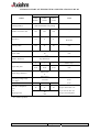
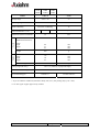
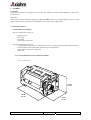
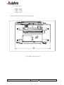
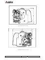
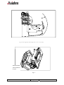
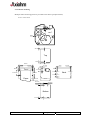
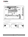
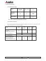
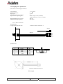
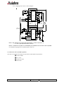
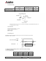
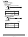
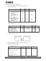
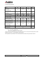
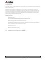
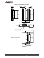
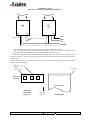
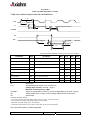
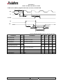
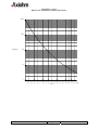
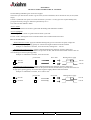
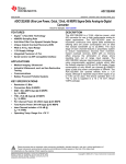
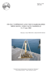
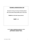
THERMAL PRINTING SOLUTIONS CL/RLxx Series USER MANUAL Reference 3108393 Issue Z February 2005 AXIOHM 1, rue d'Arcueil, BP 820 92542 MONTROUGE CEDEX FRANCE Tel : (33) 1 58 07 17 17, Fax : (33) 1 58 07 17 18 www.axiohm.com EVOLUTIONS Date 02/05 Issue Z Modifications Creation (Evolution from 2326254 with New print heads 8 dots/mm) CL/RLxx Series User Manual Page 2 /45 Reference: FDE 3108393 Issue Z IMPORTANT This manual contains the basic operations for running your printer. Read it carefully before using your printer. Pay special attention to the chapter “Recommendations”. CL/RLxx Series User Manual Page 3 /45 Reference: FDE 3108393 Issue Z CONTENTS SUMMARY CHART OF THE PRINTER’S SPECIFICATIONS CL/RL BI................................................. 5 1 - GENERAL ....................................................................................................................................................... 7 2 - SPECIFICATIONS ......................................................................................................................................... 7 2.1 Mechanical specifications ........................................................................................................................... 7 2.1.1 Overall dimensions of the complete mechanism:................................................................................... 7 2.1.1.1 CLxx series ..................................................................................................................................... 7 2.1.1.2 RLxx series ..................................................................................................................................... 8 2.1.2 Chassis mounting ................................................................................................................................. 11 2.1.2.1 CLxx series ................................................................................................................................... 11 2.1.2.2 RLxx series ................................................................................................................................... 12 2.1.3 Opto-sensor position ............................................................................................................................ 12 2.2 Electrical Specifications............................................................................................................................ 13 2.2.1 Nominal Power supply......................................................................................................................... 13 2.2.2 Nominal Consumption ......................................................................................................................... 13 2.2.3 Stepping motor specifications .............................................................................................................. 14 2.2.3.1 Motor connection .......................................................................................................................... 14 2.2.3.2 Stepping motor electric control, diagram ...................................................................................... 15 2.3 Cutter D.C. motor (for RLxx printers) ................................................................................................... 15 2.3.1 Characteristics ...................................................................................................................................... 16 2.3.2 Connection ........................................................................................................................................... 16 2.3.3 Driving cycle........................................................................................................................................ 16 2.4 Micro-switches specifications (when fitted) ............................................................................................ 17 2.4.1 Connection specifications .................................................................................................................... 17 2.5 Opto-sensor specifications (when fitted) ................................................................................................. 18 2.6 Print head specifications........................................................................................................................... 20 3 - OPERATION ................................................................................................................................................. 21 3.1 Paper feed .................................................................................................................................................. 21 3.1.1 Motor feed Timing Diagram ................................................................................................................ 21 3.1.2 Rear feed .............................................................................................................................................. 22 3.1.3 Front feed ............................................................................................................................................. 22 3.2 Printing ...................................................................................................................................................... 23 4 - RECOMMENDATIONS............................................................................................................................... 26 5 - SOLVING PROBLEMS................................................................................................................................ 28 6 - MAINTENANCE........................................................................................................................................... 29 APPENDIX 1....................................................................................................................................................... 30 APPENDIX 2....................................................................................................................................................... 31 APPENDIX 3....................................................................................................................................................... 33 APPENDIX 4....................................................................................................................................................... 34 APPENDIX 5....................................................................................................................................................... 35 APPENDIX 6....................................................................................................................................................... 36 APPENDIX 7....................................................................................................................................................... 37 APPENDIX 8....................................................................................................................................................... 39 APPENDIX 9....................................................................................................................................................... 43 APPENDIX 10..................................................................................................................................................... 45 CL/RLxx Series User Manual Page 4 /45 Reference: FDE 3108393 Issue Z SUMMARY CHART OF THE PRINTER’S SPECIFICATIONS CL/RL BI VALUE ITEM CLBI* RLBI* CLBG* CLDG CLBT* CLDT UNIT Printing method Static thermal dot line printing - Number of resistor dots 192 384 384 - Resolution 3.8 8 8 Dots/mm Printing width 50.7 1 1 Motor steps 0.26 0.125 0.125 mm Microswitch or Opto-sensor Operating voltage range Vcc (logic) Vcc Stepping motor - 2 Paper empty detection Current Consumption: Vch mm mm By Thermistor Head T° detection Vch (dot) 48 +0 60 -0.1 Paper width Paper feed pitch 48 - 4.75-5.25 V DC 20-26 20-28 10-15 43 23 25 V DC mA per resistor dot "on" µA per resistor dot "on" mA per activated phase 80 300 * Not standard products. CL/RLxx Series User Manual Page 5 /45 Reference: FDE 3108393 Issue Z CLBI RLBI ITEM CLBG CLDG CLBT CLDT VALUE UNIT Storage range - 40 to + 70 °C Operating range - 10 to + 70 °C max 90 no condensing % Relative humidity Electrical lifetime* (× 108 ) 1 1 Mechanical (abrasion) lifetime* 1 pulse 50 Km 80 57 63 mm mm mm Weight 260 g Dimensions: Width Depth Height 115 80 95 mm mm mm 720 g For RL For CL Dimensions (with standard internal motor) : Width Depth Height Weight Cutting angle (RL only) 89 ± 0.5° (relatively to paper side edge) Cutter lifetime (RL only) 1 million cuts * Recommended paper 2320061 ** Axiohm reference * As per Axiohm test conditions (which are mainly 24V, 25°C, dot printing duty cycle = 30%) ** Or other types of paper approved by Axiohm CL/RLxx Series User Manual Page 6 /45 Reference: FDE 3108393 Issue Z 1 - GENERAL Unpacking Each printer mechanism is packaged in an anti-static bag. Observe precautions while handling in electrostatic protected areas. Overview Based on static thermal printing technology, the CLxx and RLxx series are a complete family of easy to use and highly reliable devices, which have been designed to suit a wide range of applications. 2 - SPECIFICATIONS 2.1 Mechanical specifications The CLxx mechanism consists of: - Stepping motor - Drive gear - Print head - End of paper opto-sensor The RLxx mechanism consists of: - A rugged metal hinged chassis containing the printer CLxx (opening part) and the cutter (fixed part) - Cutter with DC motor and mechanical switch for position detection - Paper detection opto-sensor (optional) - Cutter exit 2.1.1 Overall dimensions of the complete mechanism: 2.1.1.1 CLxx series Height 63 mm Width 80 mm CL/RLxx Series User Manual Depth 57 mm Page 7 /45 Reference: FDE 3108393 Issue Z 2.1.1.2 RLxx series Height: Depth: Width: Weight: 95 mm 80 mm 115 mm 720 g See the mechanical illustrations on the following pages: Fig. 1 Width of printer (115 mm) CL/RLxx Series User Manual Page 8 /45 Reference: FDE 3108393 Issue Z Fig. 2 Height of printer (78 mm) Fig.3 Depth of printer (91 / 95 mm) CL/RLxx Series User Manual Page 9 /45 Reference: FDE 3108393 Issue Z Fig. 4 Size of printer when open (29,5 + 85 = 114,5 mm) 8mm maximum 5mm minimum to open Fig. 5 CL/RLxx Series User Manual Page 10 /45 Reference: FDE 3108393 Issue Z 2.1.2 Chassis mounting Multiple chassis mounting points are provided on the chassis (peripheral holes) 2.1.2.1 CLxx series 2mm 3.5 mm Top 4 mm 23.8 mm 80 mm 3 mm 12 mm 3.5 mm 8.7 mm Front 31.5 mm 4 mm 3.5 mm 20 mm 24 mm 17.5 mm 63 mm Back 17.5 mm Paper 10.5 mm 15.5 mm 55 mm 26.8 mm 4 mm Bottom 3.5 mm CL/RLxx Series User Manual Page 11 /45 Reference: FDE 3108393 Issue Z 2.1.2.2 RLxx series Use 6-32 (U.S.) screws or M4 (Europe) . 2.1.3 Opto-sensor position The position of the end of the paper opto-sensor in relation to the paper allows top off form detection. Printable side of paper 8 15 rear paper entry CL/RLxx Series User Manual Printable side of paper paper path direction 8 Printable side of paper 12 17 bottom paper entry Page 12 /45 12 optional paper out sensor Reference: FDE 3108393 Issue Z 2.2 Electrical Specifications 2.2.1 Nominal Power supply Printer xxBI - xxBG xxDG xxBT - xxDT 5 24 5 12 V DC V DC 24 12 V DC Print head : Logic (Vcc) Dot line Stepping Motor Units *Note: The Vcc and the Vch grounds must be separated. 2.2.2 Nominal Consumption The consumption depends on the speed: the greater the number of resistor dots "on" at the same time, the higher the speed will be for a given power-supply. Printer xxBI xxBG xxBT xxDG xxDT Units mA Print head : Heating current / dot (Vch) 43 Logic current/ dot (Vcc) 80 Stepping motor (2 activated phases) Maximum instantaneous current per dot line (at nominal voltage (24V / 12V) CL/RLxx Series User Manual 23 25 110 µA 600 8.2 8.8 Page 13 /45 mA 9.6 A Reference: FDE 3108393 Issue Z 2.2.3 Stepping motor specifications (This motor is used for paper advance). Coil resistance: Number of phases: Step angle: Number of steps per revolution: Paper feed for 1 printing line: Recommended control current: Maximum starting frequency: 11.5 + 0.8 Ω 2 7°30' 48 2 motor steps xx BI (=0.26mm) 1 motor step xxxG / xxxT (=0.13mm) 300 mA 500 steps/s. 2.2.3.1 Motor connection 1) CLxx series Length of the leads: 200 mm Connector: Molex serial 6471- 4 MOLEX 4 200 mm red white blue orange 1 2) RLxx series PIN n° 1 2 3 4 Wire color orange blue white red Motor B3 B1 A3 A1 A1 A2 A3 B1 B2 B3 Motor connection Connector: Molex serial 6471-4 Wire length CL/RLxx Series User Manual Page 14 /45 Reference: FDE 3108393 Issue Z 2.2.3.2 Stepping motor electric control, diagram 820 pF 16 1 56 kΩ 1k PBL 3717 Phase A I0 A 9 8 820pF Rs I1 A 24 V +5V stepper motor 820 pF From µprocessor 16 1 56 kΩ 1k PBL 3717 Phase B I0 B 9 8 Rs 820pF I1 B Note 1: Rs: resistors of 0.8 ohm with I0A and I0B = 1 and I1A and I1B = 0 --->I = 0,3 A (the required control current) Note 2: to obtain 0.8 Ω (which is not standard) it is possible to set 1Ω and 4.75Ω in parallel. For a different stepping motor command, please contact us. 2.3 Cutter D.C. motor (for RLxx printers) The cutter is mounted to the fixed part of the chassis and includes the parts below: Ceramic blades D.C. motor Cutter drive train Cam switch CL/RLxx Series User Manual Page 15 /45 Reference: FDE 3108393 Issue Z 2.3.1 Characteristics RLBI-RLDC-RLBG printer RLBT-RLDT printer unit Nominal tension of usage 24 12 V Maximum current 150 300 mA Fig. 18 Cutter The distance dot line/cut line is 22 ± 1mm, but the maximum recommended feed back after cut to avoid paper jam is 10 mm. 2.3.2 Connection Length of the leads: 250mm +/- 15 mm Connector: Molex serial 6471- 2 Negative on pin 1 Positive on pin 2 2.3.3 Driving cycle At initial start-up the cam switch on the drive gears of the cutter should be closed, and the blades in the « open » position. +V alim Power on DC motor 0 -V alim t t1 t3 1 t2 Switch status 0 t t1 : Delay between the beginning of motor rotation and switch state change. t2 : Duration of rotation t3 : 15 ms (braking time) V alim 20 v / 10 v 24 v / 12 V 30 v / 14 v t1 120 ms 100 ms 90 ms t2 420 ms 350 ms 290 ms CL/RLxx Series User Manual Page 16 /45 Reference: FDE 3108393 Issue Z 2.4 Micro-switches specifications (when fitted) Contact resistance : 30 mΩ Maximum rating : 2A at 6 V DC 2.4.1 Connection specifications 1) CLxx series and RLxx series end of paper micro-switch specifications. Orange 1 2 3 black Leads length: 200 mm Connector: Molex serial 6471- 3 Wires Contact status Paper Open Paper present Closed No paper Open No paper Closed Paper present Black /Orange Black/Green 2) RLxx series Cutter micro-switch specification. Orange 1 2 3 black Leads length: 300 mm Connector: Molex serial 6471- 3 Wires 1: green 2: orange 3: black Contact status Blade position Open Open Closed Closed Open Closed Closed Open Black /Orange Black/Green CL/RLxx Series User Manual Page 17 /45 Reference: FDE 3108393 Issue Z 2.5 Opto-sensor specifications (when fitted) 1) CLxx series and RLxx series paper end detection opto-sensor. Absolute Maximum ratings LED Continuous Forward Current Pulsed Forward Current tp < 10 µs Reverse voltage Max. Power Dissipation at 25 °C max PHOTO-TRANSISTOR Collector Emitter Voltage Collector Current Collector Dissipation at 25°C max SYMBOL RATING UNIT IF IFsm 50 3 mA A VR P 5 100 V mW VCEO IC PC 30 50 100 V mA mW Input / Output Conditions SYMBOL CONDITIONS TYP UNIT LED Forward Current Reverse Current VR IR IF = 50mA VR = 5V 1.25 100 V µA TRANSFER CHARAC. Photo-electric Current IC IF = 20 mA, VCE = 5 V 500 µA Position in relation to the paper 2) RLxx series paper detection opto-sensor (cutter exit sensor). Ref: Honeywell HOA1404-002 Absolute Maximum ratings SYMBOL RATING UNIT Continuous Forward Current If 50 mA Reverse voltage VR 3 V P 75 mW LED Max. Power Dissipation at 25°C max CL/RLxx Series User Manual Page 18 /45 Reference: FDE 3108393 Issue Z PHOTO-TRANSISTOR Collector Emitter Voltage VCEO 30 V Collector Current IC 30 mA Collector Dissipation at 25°C max PC 75 Mw Input / Output Conditions SYMBOL CONDITIONS TYP. UNIT VF IR IF=20 mA VR=3v 1,6 10 V µA IC IF=30 mA,VCE=5V 800 µA LED Forward voltage Reverse current TRANSFER CHARAC. Photo-electric current Connection Wires length: 330 mm Connector: Molex serial 6471- 3 Vcc (5V) R kΩ CPU PORT 74HC04 1: green: collector 2: orange: anode 3: black: cathode-emitter 5V pulse Opto-sensor 68 Ω 1 green 2 orange 3 black GND * R = 10 kΩ for output detection Opto-sensor, R = 4,7 for paper end detection Opto-sensor CL/RLxx Series User Manual Page 19 /45 Reference: FDE 3108393 Issue Z 2.6 Print head specifications Printer Driver chips xxBI xxBG xxDG xxBT xxDT UNITS 3 6 6 - 20-26,4 20-28 10-15, 2 (32) (32V) (16) 560+ 10% 1000+ 3% 480+ 10% Ω 24 24 12 V DC (64 bit CMos LSI) Voltage operating range (Stand by) Mean dot resistance Nominal dot supply voltage LSI supply voltage Nominal dot Energy * Total cycle time conditions Heating current per dot 5 V DC V DC 1.2 0.34 0.42 (4.4ms/line) (4ms/line) (5ms/line) 43 23 25 mA 8.2 8.8 9.6 A mJ Maximum instantaneous current per dot line (at nominal voltage) Maximum duty cycle 50 % Optical density * 1.2 - * E = ( Vch 2/ R) x heating time Duty cycle = Heating time / Total cycle time All the dots can be heated at the same time, taking particular care of the print head temperature, which should not exceed 60 ° C (with medium sensitivity paper). These parameters, especially the vch, are measured at the terminal of the print head connector. CL/RLxx Series User Manual Page 20 /45 Reference: FDE 3108393 Issue Z 3 - OPERATION Read the recommendations in chapter 4 carefully before using your printer. To connect the printer, refer to the paragraph 2.2.3.1 (Motor connection) and to appendix 7 (charts and diagrams). 3.1 Paper feed 3.1.1 Motor feed Timing Diagram RED BLUE WHITE ORANGE STEP 1 STEP 2 STEP 3 STEP 4 Voltage on cable is negative where shown as “-“. Voltage on cable is positive where shown as “+”. current into winding A Currents removed t1 t2 current into winding B Currents restored Motor Steps Motor initialisation: This operation is necessary to place the motor in a good position when it is powered. Both phases must be powered with the same current during t1=1 ms. It must be followed by 16 motor steps in order to compensate the backlash in the gears. Printing mode: There are 4 different positions for the motor phases. If P1 = A; P2 = B The circulation is: ___ _____ ___ AB ⇒ AB ⇒ AB ⇒ AB ⇒ AB The position of the phases must be memorised while the phase currents are switched to zero in order to restart the motor in good position. IP = ± 300 mA t2 > 2 ms When the printing speed requires a motor phase lower than 2 ms (1.67 for example), an acceleration curve of 2 to 1.67 must be used; this acceleration can be done over 16 steps. CL/RLxx Series User Manual Page 21 /45 Reference: FDE 3108393 Issue Z Paper loading: When starting the paper advance for paper stock loading the energising time (t2) must be increased to 6ms with a current (IP) of +500mA. 3.1.2 Rear feed Angle of paper exit Paper introduction tolerance angle 45° 30° 47.5 mm 40° 35.5 mm Distance from paper end sensor to resistor dot line (nominal) With microswitch : 33 mm With opto-sensor : 42 mm 3.1.3 Front feed Angle of paper exit (Same as rear feed) Paper introduction tolerance angle 45° 21.2 mm 60° Distance from paper end sensor to resistor dot line (nominal) With microswitch : 33 mm With opto-sensor : 33 mm CL/RLxx Series User Manual Page 22 /45 Reference: FDE 3108393 Issue Z 3.2 Printing There are several ways of driving the printer. Here are three possible modes. Mode 1 - The paper advance occurs during the heating cycle. (High speed can be achieved). (In this mode, it is recommended to use historical control, see page 27) Printing of n dot line Transmission of data in series (Din) in step with CLK Transfer to memory stage (STROBE) Transmission of next series of data Heating order through OE 1,OE 2,...OEn simultaneously Motor feed 1 to n End of printing CLK T Din N Strobe OE 1 OEn Motor Steps CL/RLxx Series User Manual Page 23 /45 Reference: FDE 3108393 Issue Z Mode 2 - The paper advance occurs after the heating cycle (high quality of printing). Printing of n dot line Transmission of data in series (Din) in step with CLK Transfer to memory stage (STROBE) Heating order through OE 1,OE 2,...OEn simultaneously Transmission of next series of data Motor feed 1 to n End of printing CLK T Din N Strobe OE 1 OEn Motor Steps CL/RLxx Series User Manual Page 24 /45 Reference: FDE 3108393 Issue Z Mode 3 - The dot line is printed in stages, heating only a portion of the line at a time (consumption reduced). Printing of n dot line Transmission of data in series (Din) in step with CLK Transfer to memory stage (STROBE) Heating order through OE 1,OE 2,...OEn successively or in blocks Transmission of next series of data Motor feed 1 to n End of printing Clock CLK T Din (serial input) N N Strobe OE 1 OEn Motor Steps CL/RLxx Series User Manual Page 25 /45 Reference: FDE 3108393 Issue Z 4 - RECOMMENDATIONS 1 - Never apply mechanical stress to the printer because this could cause misalignment and degrade print quality. The thermal print head must have 1 degree-of-freedom. Never prevent the print head from pivoting on its axis. 2 - IMPORTANT NOTE: When energising the thermal print head (Vcc, 5 V) it is important to apply all the logic signals within 10 ms (particularly to de-energise all the OEs). If the line of dots (Vch, 24 / 12 V) is supplied before the control logic, resistor dots may be destroyed. Because the control logic has a random state, resistors might be heated for a longer period than the specified maximum, burning out the heated resistor. To avoid this, we recommend applying the heating voltage (Vch, 24 / 12 V) after the logic supply voltage (Vcc, 5V). The same precaution should be taken at shut down. The supply voltage Vch must be switched off before the logic supply voltage Vcc. Care should be taken to allow enough time for residual capacitive charge to dissipate. 3 - Paper drive recommendations: Use the roll of paper classified with an AXIOHM reference (or agreed by Axiohm). Use a paper roll with maximum diameter of 230 mm Leave the paper stock spool free to turn. Do not run the printer without paper or this will damage the surface of the rubber roller. Provide adequate air circulation to the print head support/heat sink. Poor ventilation can degrade the print quality. To facilitate the insertion of the paper, fold the end to be inserted at an angle. The point of the angle must be opposite of the paper switch. When using a big roll make sure that the paper between the printer roller and the paper stock spool is not tight, but forms a slight loop. Tight paper can make it difficult for the motor to start the paper feed and may lead to poor print quality on the first line (see drawing on next page). 4 - Motor drive recommendations There is a resonance frequency to avoid, therefore the paper feed motor should not be driven between 125 to 185 step per second (motor phase between 5.5 to 8 ms). CL/RLxx Series User Manual Page 26 /45 Reference: FDE 3108393 Issue Z 5 - General Never open the mechanism while printing or cutter operating. To avoid E.S.D. problems, it is very important to connect the metallic parts, (print head & cutter) to the frame by using the hole on the spring above the print head. In order to prevent paper jam, it is recommended to advance the paper 1mm after the cut line when the printer is in stand-by mode. CL/RLxx Series User Manual Page 27 /45 Reference: FDE 3108393 Issue Z 5 - SOLVING PROBLEMS The CL/RLxx printer is a simple, generally trouble-free printer, easy to drive, but from time to time minor problems may occur. The information below describes some problems that you may encounter: problems that you can easily fix, and others requiring to contact a service representative. Problem Printing is light or spotty What to do Ensure that you are using the correct paper with the right sensitivity. Ensure that you are driving the print head with the correct energy. Ensure that the spring on the print head is in the correct position. The thermal print head may be dirty, clean it with cotton swabs and rubbing alcohol. AXIOHM provides such cleaning kits: ref. CK600001. Caution: some types of paper can be very abrasive and damage the print head. Use only the paper references agreed by AXIOHM Note: The thermal print head does not normally require cleaning if the recommended paper grades are used. Missing dots in ticket printing Ensure that the print head connection is correct. Contact a service representative. Printing is not centered on the paper or the paper is folded on one side Ensure that you are using a paper with the right dimensions and that the roll is in the correct position. Knife failure Check the knife. Remove all of the jammed paper. To avoid ceramic blade damages, avoid using any metallic tools (like a screwdriver). Check if the screw for pressure adjustment of the fixed blade on the rotating blade has not moved. Paper jam Check if the complete cutter mechanism is in correct position with the printer (closed). Ensure that the rotation of the blades is correct and that the blades are opened normally. Paper detection output sensor Ensure that the output opto-sensor is not dirty. CL/RLxx Series User Manual Page 28 /45 Reference: FDE 3108393 Issue Z 6 - MAINTENANCE The CL/RLxx printers are high reliability units, which require very little maintenance but may benefit from cleaning as detailed below. Depending on the environment in which the printer is used, the printer can accumulate dust. Therefore it is necessary to clean it periodically in order to maintain a good print quality. The cleaning period depends on the environment and the usage of the printer, but the print head should be cleaned at least once a year or up to one month in heavy duty applications. The print head should always be cleaned immediately if the print becomes visibly pale due to contamination of the print head. Cleaning instructions: Switch off the printer. Never clean the head immediately after printing, the head may be hot. Remove the spring and the print head from the mechanism. Clean the heating dots of the head with a cotton stick containing a solvent alcohol (ethanol, methanol, or IPA), but do not touch the print head with your fingers! Allow the solvent to dry. Replace the print head and the spring. N.B. AXIOHM can provide cleaning kits, ref.: CK60000A CL/RLxx Series User Manual Page 29 /45 Reference: FDE 3108393 Issue Z APPENDIX 1 DIMENSIONS OF PRINTHEAD ASSEMBLY 10.8 mm 3.5 mm 6.1 mm 41 mm 3 mm 60 mm 18.85 ± 0.1mm 42.1 mm 30 mm 6.1 mm 16.1 mm Max. 17.4 mm 7 mm Note : The dimensions given in milimeters are exact, but the diagram may not be to scale 46 mm M 2.5 mm 26 mm CL/RLxx Series User Manual Page 30 /45 Reference: FDE 3108393 Issue Z APPENDIX 2 64-BIT LSI DRIVERS CHART AND OPERATION The LSI power and de-multiplexing circuit drivers located on the thermal print head provide power control from logic signals and the D.C. power supply voltage. These circuits are supplied by 5 V ± 5% logic voltage. Each circuit features 64 open collector transistors, a 64-bit shift register and a 64-bit memory register. Each circuit controls 64 resistor dots on the print head. CL/RLxx Series User Manual Page 31 /45 Reference: FDE 3108393 Issue Z APPENDIX 2 (contd.) ROUTING OF DATA TO THE RESISTOR DOTS R1 Resistors R64 R1 Resistors CHIP 1 SI R 64 CHIP N SO SO SI OUT IN OE 1 OE N CLK STROBE - Data to be printed is clocked into a shift register formed by cascading "n" chips. - E.g. 384 dots head uses 6 chips with the SO output of chip 1 used as the SI input for chip 2 etc. Respectively, the SO output of chip 2 is used as the SI input for chip 3 etc. After 384 clocks, the initial piece of data entered corresponds to the last (384th) dot of the line (the R64 output of the 6th chip). The last bit of data entered will correspond to the first dot of the line (R1 of the first chip). The first dot of the line is the dot at the far left when looking at the head itself, or at the far right dot when looking at the printed paper. Line of dots R1 of chip 1 R1 of chip 1 Print head substrate chip 1 chip n Sensitive side Print head bottomview paper side CL/RLxx Series User Manual paper feed direction Thermal paper Page 32 /45 Reference: FDE 3108393 Issue Z APPENDIX 3 ELECTRICAL SPECIFICATIONS OF 64-BIT LSI DRIVER FOR xxBI PRINTERS The specifications given below are for the following conditions: Logic voltage on chip Clock frequency : : 4.75V < Vdd < 5.25V 8 Mhz (Max) (Unless otherwise specified: VDD=5.0 V= ±5%, Ta=25°C) Parameter Sybl Conditions Min. Typ. Max. Unit Supply voltage VDD 4.75 5.0 5.25 V High level input voltage VIH 0.7x VDD __ VDD V Low level input voltage VIL VSS __ 0.3x VDD V __ __ µA IIH VDD=5.0 V VIH=5.0 V Ta=25°C __ High level input current __ __ 0.5 µA __ __ µA IIL VDD=5.0 V VIL=0 V Ta=25°C __ Low level input current -0.5 __ __ µA High level output voltage VOH SO terminal, no load 4.45 __ __ V Low level output voltage VOL SO terminal, no load __ __ 0.05 V High level output current IOH SO terminal, VOH= VDD=0.4 V __ __ -0.5 µA Low level output current IOL SO terminal, no load 0.5 __ __ µA High level driver output voltage VDOH __ 24 26.4 V Driver leakage current ILEAK __ __ 30.0 µA Current consumption IDD __ __ 15 mA CL/RLxx Series User Manual VDOH=26 V All low Ta=25°C All high Page 33 /45 Reference: FDE 3108393 Issue Z APPENDIX 4 64 BIT LSI DRIVER TIMING CHART TYPICAL LOADING SEQUENCE FOR xxBI PRINTERS 1/fCLK CLK tWCLK SI tSUD tSULA tHD tWLA STROBE OE DOn 90% tdDO tfDO trDO 10% tdDO (Unless otherwise specified: VDD=5.0 V=5%, Ta=-10°C to 80°C) Parameter Sybl Conditions Min. Typ. Max. Unit 50 __ __ ns CLK pulse width tWCLK Data set up time tSUD VIH= VDD, VIL= VSS0 20 __ __ ns Data hold time tHD VIH= VDD, VIL= VSS0 10 __ __ ns Stroke pulse width tWLA 100 __ __ ns Clock-stroke set up time tSULA 100 __ __ ns OE-DOn propagation delay time tdDO RL= 1 kΩ, VDOH=24 V __ __ 10.5 µs Don rise time trDO RL= 1 kΩ, VDOH=24 V __ 2.0 6.0 µs Don fall time tfDO RL= 1 kΩ, VDOH=24 V __ 3.5 10.0 µs Clock frequency fCLK Chip __ __ 8 MHz SI CLK : : Serial input Serial/parallel shift register clock, activated on leading edge of pulse (rest level = logic 0) Maximum clock frequency: 8 MHz. STROBE : Signal for putting data into memory, active on logic level 1 (rest level = logic 0) OE : Output Enable (OE1 to OE5): power activation signals active at logic level SO : Serial output TIMING RESTRICTIONS - No clock transitions may take place during Tscl, tst, Tdoes, Tdoec,and Tdcoe, - Data input must change on the falling edge of the clk-input, Data must be stable during Tsdc, Tr and Thdc. - The Strobe signal must not occur until 10,5µs after the drop in the OE signal. Note: All of these inputs are CMOS compatible. CL/RLxx Series User Manual Page 34 /45 Reference: FDE 3108393 Issue Z APPENDIX 5 ELECTRICAL SPECIFICATIONS OF 64-BIT LSI DRIVER FOR xxxG OR xxxT PRINTER The specifications given below are for the following conditions: Logic voltage on chip Clock frequency : : 4.75V < Vdd < 5.25V 4 Mhz (Max) (Unless otherwise specified: VDD=5.0 V= ±5%, Ta=25°C) Parameter Sybl Conditions Min. Typ. Max. Unit Supply voltage VDD 4.75 5.0 5.25 V High level input voltage VIH 0.7x VDD __ VDD V Low level input voltage VIL VSS __ 0.3x VDD V IIH VDD=5.0 V VIH=5.0 V Ta=25°C __ __ __ µA High level input current __ __ 0.5 µA IIL VDD=5.0 V VIL=0 V Ta=25°C __ __ __ µA Low level input current -0.5 __ __ µA High level output voltage VOH SO terminal, no load 4.45 __ __ V Low level output voltage VOL SO terminal, no load __ __ 0.05 V High level output current IOH SO terminal, VOH= VDD=0.4 V __ __ -0.5 µA (xxxG) (xxxT) __ 24 12 26.4 15.2 V VDOH=26 V __ __ 4.0 mA __ __ 42 mA High level driver output voltage VDOH Driver leakage current ILEAK Current consumption IDD CL/RLxx Series User Manual All low Ta=25°C All high Page 35 /45 Reference: FDE 3108393 Issue Z APPENDIX 6 64 BIT LSI DRIVER TIMING CHART TYPICAL LOADING SEQUENCE FOR xxxG OR xxxT PRINTER 1/fCLK CLK tWCLK SI tSUD tSULA tHD tWLA STROBE OE DOn 90% tdDO tfDO trDO 10% tdDO (Unless otherwise specified: VDD=5.0 V, Ta=-10°C to 70°C) Parameter Sybl Conditions Min. Typ. Max. 70 __ __ Unit CLK pulse width tWCLK Data set up time tSUD VIH= VDD, VIL= VSS0 50 __ __ Data hold time tHD VIH= VDD, VIL= VSS0 10 __ __ __ __ ns 2 µs ns ns ns Stroke pulse width tWLA 100 __ Clock-stroke set up time tSULA 100 __ OE-DOn propagation delay time tdDO RL= 1 kΩ, VDOH=24 V __ __ Don rise time trDO RL= 1 kΩ, VDOH=24 V __ __ 2 µs RL= 1 kΩ, VDOH=24 V __ __ 0.5 µs Chip __ __ 4 MHz Don fall time Clock frequency CL/RLxx Series User Manual tfDO fCLK Page 36 /45 ns Reference: FDE 3108393 Issue Z APPENDIX 7 THERMISTOR SPECIFICATIONS This thermistor has a rated value of 100 kΩ ± 5% at 25°C Its resistance variation can be expressed as follows: R = Rn exp B ( 1 - 1 ) T Tn B = 4066 K ± 3% where T is in kelvin degrees (k) Rn: reference value at temperature Tn (298°K) T (°K) = 277,15 Tn (°K) = 273.15 + each temperature (°C) The main specifications of the thermistance are listed in the following pages. GENERAL CHARACTERISTICS * Climatic category (IEC) 40/85/56 * Maximum operating temperatures: -55°C to +150°C * Tolerance for Rn : 5% * Maximum dissipation at 25° C : Pmax = 0.24mW * Thermal dissipation factor : ∂ = 4 mW/°C * Thermistor time constant / dot line: t = 7 sec * Resistance value as a function of temperature (see curves) CL/RLxx Series User Manual Page 37 /45 Reference: FDE 3108393 Issue Z APPENDIX 7 (contd.) RESISTANCE/TEMPERATURE VARIATIONS 10000 1000 R (kOhms) 100 10 1 -40° -30 -20 -10 0 10 20 30 40 50 60 70 80 90 100 110 120 130 T (°C) CL/RLxx Series User Manual Page 38 /45 Reference: FDE 3108393 Issue Z APPENDIX 8 HEATING TIME AND HISTORICAL CONTROL See the Heating timetables given on the next 4 pages. The motor cycle time for one dot line is given in the (b) line of the tables; this is the time for one (or two) motor step(s). Column 3 (indicated with: speed <xxx mm/s and motor cycle time > xxx ms) gives the required heating time, giving the necessary energy to obtain an optical density of 1.2. Two areas are then defined in tables. Area 1: "white" The motor cycle time for one dot line is greater than the heating time indicated in column 3. Area 2: highlighted The heating time in column 3 is greater than the motor cycle time. In areas 1 and 2, heating time can be controlled either with or without historical control. How to use the tables? - Without historical control: apply the indicated heating time given as a function of speed, voltage and temperature. At high speed, printing quality for isolated dots might be affected with this method. Example: in xxBI table at 50 mm/s, 30°C and 24 volts, heating time = 1.85 ms - With historical control in area 1: apply the indicated heating time (function of speed, voltage and temperature) when the dot has been heated on the previous dot line, and the time from column 3 when it has not. This method gives the best printing quality. Example: in xxBI table at 55 mm/s, 25°C and 24 volts: previous dot dot to heat Heating time to apply dot ON 1.88 ms dot OFF 3.78 ms - With historical control in area 2: apply the indicated heating time (function of speed, voltage and temperature) when the dot has been heated on the previous dot line, and the motor cycle time when it has not. At high speed, printing quality for isolated dots might be slightly affected with this method. Example: in xxBI table at 70 mm/s, 20 °C and 22 volts: previous dot dot to heat Heating time to apply dot ON 2.14 ms dot OFF 3.78 ms CL/RLxx Series User Manual Page 39 /45 Reference: FDE 3108393 Issue Z APPENDIX 8 (contd.) HEATING TIME FOR CLBI AND RLBI PRINTER xxBI: Tch = f(V,T,v) for: R565 Ω, paper used KP 440 (2320061), density = 1,2 Voltage Temp °C Time for one motor step Motor cycle time for one dot line 20 Volts 0 °C 20 Volts 10 °C 20 Volts 20 °C 20 Volts 30 °C 20 Volts 40 °C 20 Volts 50 °C 22 Volts 0 °C 22 Volts 10 °C 22 Volts 20 °C 22 Volts 30 °C 22 Volts 40 °C 22 Volts 50 °C 24 Volts 0 °C 24 Volts 10 °C 24 Volts 20 °C 24 Volts 25 °C 24 Volts 30 °C 24 Volts 40 °C 24 Volts 50 °C 26 Volts 0 °C 26 Volts 10 °C 26 Volts 20 °C 26 Volts 30 °C 26 Volts 40 °C 26 Volts 50 °C CL/RLxx Series User Manual R=565 Ohm Speed (mm/s) < 4,9 mm/s 20 mm/s 30 mm/s 40 mm/s 50 mm/s 55 mm/s 60 mm/s 70 mm/s 80 mm/s > 27 ms 6,61 ms 4,41 ms 3,31 ms 2,65 ms 2,41 ms 2,2 ms 1,89 ms 1,65 ms 13,2 ms 8,82 ms 6,62 ms 5,3 ms 4,82 ms 4,4 ms 3,78 ms 3,3 ms 7 6,44 5,88 5,32 4,76 4,2 5,69 5,24 4,78 4,33 3,87 3,42 4,72 4,34 3,97 3,78 3,59 3,21 2,83 3,98 3,66 3,34 3,02 2,71 2,39 4,95 4,55 4,16 3,76 3,37 2,97 4,03 3,7 3,38 3,06 2,74 2,42 3,34 3,07 2,8 2,67 2,54 2,27 2 2,81 2,59 2,36 2,14 1,91 1,69 4,36 4,01 3,66 3,31 2,96 2,62 3,55 3,26 2,98 2,7 2,41 2,13 2,94 2,71 2,47 2,35 2,24 2 1,76 2,48 2,28 2,08 1,88 1,69 1,49 3,94 3,63 3,31 3 2,68 2,36 3,21 2,95 2,69 2,44 2,18 1,92 2,66 2,45 2,23 2,13 2,02 1,81 1,6 2,24 2,06 1,88 1,7 1,52 1,34 Page 40 /45 3,62 3,33 3,04 2,75 2,46 2,17 2,94 2,71 2,47 2,24 2 1,77 2,44 2,25 2,05 1,95 1,85 1,66 1,46 2,06 1,89 1,73 1,56 1,4 1,23 3,48 3,2 2,92 2,64 2,37 2,09 2,83 2,6 2,38 2,15 1,92 1,7 2,35 2,16 1,97 1,88 1,78 1,6 1,41 1,98 1,82 1,66 1,5 1,35 1,19 3,35 3,08 2,81 2,54 2,28 2,01 2,72 2,5 2,29 2,07 1,85 1,63 2,26 2,08 1,9 1,81 1,72 1,54 1,35 1,9 1,75 1,6 1,45 1,29 1,14 3,13 2,88 2,63 2,38 2,13 1,88 2,54 2,34 2,14 1,93 1,73 1,53 2,11 1,94 1,77 1,69 1,6 1,43 1,27 1,78 1,63 1,49 1,35 1,21 1,07 Reference: FDE 3108393 Issue Z 2,93 2,69 2,46 2,22 1,99 1,76 2,38 2,19 2 1,81 1,62 1,43 1,98 1,82 1,66 1,58 1,5 1,34 1,19 1,66 1,53 1,4 1,26 1,13 1 APPENDIX 8 (Contd.) HEATING TIME FOR xxBG xxDG PRINTER xxBG/xxDG: Tch = f(V,T,v) for: R 700 Ω, paper used KP440 (2320061), density = 1,2 Voltage Temp Volts 20 20 20 20 20 20 22 22 22 22 22 22 24 24 24 24 24 24 24 26 26 26 26 26 26 28 28 28 28 28 28 °C 0 10 20 30 40 50 0 10 20 30 40 50 0 10 20 25 30 40 50 0 10 20 30 40 50 0 10 20 30 40 50 CL/RLxx Series User Manual < 5 mm/s 20 mm/s 30 mm/s 40 mm/s 50 mm/s 55 mm/s 60 mm/s 70 mm/s 80 mm/s > 27 ms 6,58 ms 4,39 ms 3,29 ms 2,63 ms 2,39 ms 2,19 ms 1,88 ms 1,64 ms 2,37 2,18 1,99 1,8 1,61 1,42 1,96 1,8 1,65 1,49 1,33 1,18 1,65 1,52 1,38 1,32 1,25 1,12 0,99 1,4 1,29 1,18 1,07 0,96 0,84 1,21 1,11 1,02 0,92 0,82 0,73 1,57 1,45 1,32 1,2 1,07 0,94 1,3 1,2 1,09 0,99 0,88 0,78 1,09 1,01 0,92 0,87 0,83 0,74 0,66 0,93 0,86 0,78 0,71 0,63 0,56 0,8 0,74 0,67 0,61 0,55 0,48 1,35 1,24 1,13 1,02 0,91 0,81 1,11 1,02 0,93 0,85 0,76 0,67 0,93 0,86 0,78 0,75 0,71 0,64 0,56 0,8 0,73 0,67 0,61 0,54 0,48 0,69 0,63 0,58 0,52 0,47 0,41 1,18 1,09 0,99 0,9 0,8 0,71 0,98 0,9 0,82 0,74 0,66 0,59 0,82 0,76 0,69 0,66 0,62 0,56 0,49 0,7 0,64 0,59 0,53 0,48 0,42 0,6 0,55 0,51 0,46 0,41 0,36 1,06 0,97 0,89 0,8 0,72 0,63 0,87 0,8 0,73 0,66 0,59 0,52 0,73 0,67 0,62 0,59 0,56 0,5 0,44 0,62 0,57 0,52 0,47 0,42 0,37 0,54 0,5 0,45 0,41 0,37 0,32 1 0,92 0,84 0,76 0,68 0,6 0,83 0,76 0,7 0,63 0,56 0,5 0,7 0,64 0,58 0,56 0,53 0,47 0,42 0,59 0,55 0,5 0,45 0,4 0,36 0,51 0,47 0,43 0,39 0,35 0,31 0,95 0,88 0,8 0,72 0,65 0,57 0,79 0,72 0,66 0,6 0,53 0,47 0,66 0,61 0,56 0,53 0,5 0,45 0,4 0,56 0,52 0,47 0,43 0,38 0,34 0,49 0,45 0,41 0,37 0,33 0,29 0,87 0,8 0,73 0,66 0,59 0,52 0,72 0,66 0,6 0,54 0,49 0,43 0,6 0,55 0,5 0,48 0,46 0,41 0,36 0,51 0,47 0,43 0,39 0,35 0,31 0,44 0,41 0,37 0,34 0,3 0,26 0,79 0,73 0,66 0,6 0,54 0,47 0,65 0,6 0,55 0,5 0,44 0,39 0,55 0,5 0,46 0,44 0,42 0,37 0,33 0,47 0,43 0,39 0,35 0,32 0,28 0,4 0,37 0,34 0,31 0,27 0,24 Page 41 /45 Reference: FDE 3108393 Issue Z APPENDIX 8 (Contd.) HEATING TIME FOR xxBT xxDT PRINTER CALCULATED VALUES FOR CE365 WITH PAPER KP440 Voltage (V) Real Temperature (°C) Motor cycle time for one dot line 10,00 Volts 0 °C 10,00 Volts 10 °C 10,00 Volts 20 °C 10,00 Volts 25 °C 10,00 Volts 30 °C 10,00 Volts 40 °C 10,00 Volts 50 °C 11,00 Volts 0 °C 11,00 Volts 10 °C 11,00 Volts 20 °C 11,00 Volts 25 °C 11,00 Volts 30 °C 11,00 Volts 40 °C 11,00 Volts 50 °C 12,00 Volts 0 °C 12,00 Volts 5 °C 12,00 Volts 21 °C 12,00 Volts 25 °C 12,00 Volts 30 °C 12,00 Volts 40 °C 12,00 Volts 49,4 °C 13,00 Volts 0 °C 13,00 Volts 10 °C 13,20 Volts 21,7 °C 13,00 Volts 25 °C 13,00 Volts 30 °C 13,00 Volts 40 °C 13,00 Volts 50 °C 14,00 Volts 0 °C 14,00 Volts 10 °C 14,00 Volts 20 °C 14,00 Volts 25 °C 14,00 Volts 30 °C 14,00 Volts 40 °C 14,00 Volts 50 °C CL/RLxx Series User Manual Speed (mm/s) R = 437 Ohms < 20 mm/s 35 mm/s 40 mm/s 50 mm/s 60 mm/s 70 mm/s 80 mm/s 6,250 ms 3,570 ms 3,130 ms 2,500 ms 2,080 ms 1,790 ms 1,560 ms 2,787 ms 2,466 ms 2,275 ms 2,211 ms 2,159 ms 2,064 ms 1,935 ms 2,456 ms 2,174 ms 2,005 ms 1,949 ms 1,903 ms 1,819 ms 1,706 ms 2,182 ms 2,041 ms 1,770 ms 1,731 ms 1,690 ms 1,616 ms 1,523 ms 1,950 ms 1,726 ms 1,542 ms 1,547 ms 1,511 ms 1,445 ms 1,354 ms 1,754 ms 1,552 ms 1,432 ms 1,392 ms 1,359 ms 1,299 ms 1,218 ms 2,204 ms 1,951 ms 1,800 ms 1,749 ms 1,708 ms 1,633 ms 1,531 ms 1,943 ms 1,720 ms 1,586 ms 1,542 ms 1,506 ms 1,439 ms 1,349 ms 1,726 ms 1,614 ms 1,400 ms 1,369 ms 1,337 ms 1,278 ms 1,204 ms 1,543 ms 1,365 ms 1,220 ms 1,224 ms 1,195 ms 1,143 ms 1,071 ms 1,387 ms 1,228 ms 1,133 ms 1,101 ms 1,075 ms 1,028 ms 0,964 ms 2,068 ms 1,830 ms 1,688 ms 1,641 ms 1,602 ms 1,531 ms 1,436 ms 1,823 ms 1,613 ms 1,488 ms 1,446 ms 1,412 ms 1,350 ms 1,266 ms 1,619 ms 1,514 ms 1,313 ms 1,284 ms 1,254 ms 1,199 ms 1,130 ms 1,447 ms 1,280 ms 1,144 ms 1,148 ms 1,121 ms 1,072 ms 1,005 ms 1,301 ms 1,152 ms 1,062 ms 1,033 ms 1,008 ms 0,964 ms 0,904 ms Page 42 /45 1,834 ms 1,623 ms 1,497 ms 1,455 ms 1,421 ms 1,358 ms 1,274 ms 1,617 ms 1,431 ms 1,320 ms 1,283 ms 1,252 ms 1,197 ms 1,123 ms 1,436 ms 1,343 ms 1,165 ms 1,139 ms 1,112 ms 1,063 ms 1,002 ms 1,283 ms 1,136 ms 1,015 ms 1,018 ms 0,994 ms 0,951 ms 0,891 ms 1,154 ms 1,021 ms 0,942 ms 0,916 ms 0,894 ms 0,855 ms 0,802 ms 1,643 ms 1,454 ms 1,341 ms 1,303 ms 1,273 ms 1,217 ms 1,141 ms 1,448 ms 1,281 ms 1,182 ms 1,149 ms 1,122 ms 1,072 ms 1,006 ms 1,286 ms 1,203 ms 1,043 ms 1,020 ms 0,996 ms 0,952 ms 0,897 ms 1,150 ms 1,017 ms 0,909 ms 0,912 ms 0,891 ms 0,851 ms 0,798 ms 1,034 ms 0,915 ms 0,844 ms 0,820 ms 0,801 ms 0,766 ms 0,718 ms 1,487 ms 1,315 ms 1,214 ms 1,179 ms 1,152 ms 1,101 ms 1,032 ms 1,310 ms 1,160 ms 1,070 ms 1,040 ms 1,015 ms 0,971 ms 0,910 ms 1,164 ms 1,089 ms 0,944 ms 0,923 ms 0,902 ms 0,862 ms 0,812 ms 1,040 ms 0,921 ms 0,822 ms 0,825 ms 0,806 ms 0,771 ms 0,722 ms 0,936 ms 0,828 ms 0,764 ms 0,742 ms 0,725 ms 0,693 ms 0,650 ms Reference: FDE 3108393 Issue Z 1,344 ms 1,189 ms 1,097 ms 1,066 ms 1,041 ms 0,995 ms 0,933 ms 1,184 ms 1,048 ms 0,967 ms 0,940 ms 0,918 ms 0,877 ms 0,822 ms 1,052 ms 0,984 ms 0,853 ms 0,834 ms 0,815 ms 0,779 ms 0,734 ms 0,940 ms 0,832 ms 0,743 ms 0,746 ms 0,728 ms 0,696 ms 0,653 ms 0,846 ms 0,748 ms 0,690 ms 0,671 ms 0,655 ms 0,626 ms 0,587 ms APPENDIX 9 PINOUT OF HE10 CONNECTOR xxBI-xxBG-xxBT PRINTER PIN N° SIGNAL PIN N° SIGNAL 1 OE1 2 Vch 3 GND 4 Vch 5 GND 6 GND 7 OE2 8 Vcc 9 Strobe 10 SO 11 Clock 12 OE3 13 GND (for Vcc) 14 GND (for Vcc) 15 th 1* 16 Vch 17 th 2* 18 NC 19 NC 20 Vcc 21 GND 22 GND 23 GND 24 Vch 25 SI 26 Vch * Thermistor pin 1 pin 2 pin 26 For xxBI Chip 2 Chip 1 OE 1 Chip 3 OE 2 OE 3 For xxBG & xxBT Ch ip 1 Ch ip 2 OE 1 CL/RLxx Series User Manual Chip 3 Chip 4 OE 2 Page 43 /45 Chip 5 Ch ip 6 OE 3 Reference: FDE 3108393 Issue Z APPENDIX 9 (contd.) PINOUT OF HE10 CONNECTOR xxDG-xxDT PRINTER PIN N° SIGNAL PIN N° SIGNAL 1 Vch 2 GND 3 Vch 4 GND 5 Vch 6 GND 7 Strobe 8 SI 9 OE1 10 OE2 11 OE3 12 OE4 13 OE5 14 OE6 15 th 1* 16 th 2 * 17 NC 18 Vcc (+ 5 V) 19 Clock 20 SO 21 Vch 22 GND 23 Vch 24 GND 25 Vch 26 GND * Thermistor pin 1 pin 26 pin 2 Ch ip 1 Ch ip 2 Ch ip 3 Chi p 4 Ch ip 5 OE 1 OE 2 OE 3 OE 4 OE 5 CL/RLxx Series User Manual Page 44 /45 Ch ip 6 OE 6 Reference: FDE 3108393 Issue Z APPENDIX 10 PAPER SPECIFICATIONS (KANZAN KP440) Property Test Method Unit Value Basic weight ISO 536 g/m2 58 ± 5 Caliper (thickness) ISO 534 µ 60 ± 5 Brightness ISO 2470 % min. 75 Smoothness ISO 5627 Sec. min. 250 Tensile strength MD/CD ISO 1924/1 kN/m >3,3/>2,0 Tearing strength MD/CD ISO 1974 mN >250/>250 Moisture Content ISO 287 % 6,5 ± 1,0 Image Color Black Initial Temperature (D= 0,2) °C 75 ± 5 Effective Temperature (D= 0,8) °C 85 ± 5 O.D. Min. 1,0 Saturated Density AXIOHM ref. 2320061: - Paper Kanzan KP440 - Length: 30m - Width: 60 (+0 / -1) mm - External roll diameter 50 (+0 / -2) mm - Internal core diameter 11 (+0,2 / -0) mm CL/RLxx Series User Manual Page 45 /45 Reference: FDE 3108393 Issue Z